
 My Inquiry
 My Account


Output Capacitor Selection for High-Current ASIC Vcore Rails
In a multiphase buck converter, output capacitors provide local energy during fast current transitions, reduce rail impedance across frequency, damp converter ripple, and support the control loop while it responds to changing ASIC load current. Bulk capacitors, polymer capacitors, mid-value MLCCs, small-case MLCCs, and ASIC-side decoupling capacitors each serve different parts of the transient and frequency spectrum.
This article is the capacitor-focused follow-up to High-Current ASIC Core Power Supply Design. The system-level article covers the 12-phase buck, PMBus control, smart power stages, dynamic load response, and validation strategy. This article focuses on how engineers should select, place, verify, and substitute output capacitors in high-current ASIC Vcore rails.
Quick Answer: How Should Output Capacitors Be Selected for an ASIC Vcore Rail?
Output capacitors for an ASIC Vcore rail should be selected as a layered impedance network. Bulk capacitors support lower-frequency energy demand, polymer capacitors help with high ripple-current capability and low ESR, large MLCCs reduce mid-frequency impedance, small MLCCs support higher-frequency local current loops, and ASIC-side decoupling addresses parasitic inductance close to the load.
| Capacitor Layer | Primary Function | Key Parameters |
|---|---|---|
| Bulk capacitor | Supports lower-frequency load energy and rail stability | Capacitance, ESR, ripple current, lifetime, temperature rating, package size |
| Polymer capacitor | Provides low ESR and high ripple-current capability near the output rail | ESR, ripple current, voltage rating, lifetime, mounting footprint, thermal derating |
| Large MLCC | Reduces mid-frequency impedance and supports transient current close to the regulator | Effective capacitance, DC bias, dielectric, case size, ESR, ESL, placement |
| Small MLCC | Improves high-frequency bypassing with lower mounting inductance | Package size, ESL, self-resonant frequency, capacitance value, via placement |
| ASIC-side decoupling | Supplies local current after board and package parasitics limit regulator-side response | Distance to load pins, power-plane connection, mounting inductance, package constraints |
Why Total Capacitance Is Not Enough
A high-current Vcore rail does not fail only because the nominal capacitance is too low. It can fail because the right capacitance is in the wrong location, because MLCC effective capacitance is much lower than the BOM value, because mounting inductance dominates at high frequency, or because the capacitor network interacts poorly with the converter control loop.
The first design estimate often starts from load-step current, allowed voltage droop, and transient duration. For early sizing, the Decoupling Capacitor Calculator can estimate required capacitance, target impedance, and the approximate number of parallel MLCCs from transient current, allowed droop, frequency, ESR, and DC bias remaining percentage.
| Design View | What It Can Tell You | What It Cannot Prove Alone |
|---|---|---|
| Total capacitance | First-pass stored energy and transient support | Real impedance, bias derating, ESL, placement effect, stability |
| Target impedance | Maximum rail impedance allowed for a load step | Full frequency response without PDN simulation or measurement |
| ESR estimate | Step-related voltage change and damping contribution | High-frequency behavior dominated by ESL and mounting geometry |
| Self-resonant frequency | Frequency region where a capacitor is most effective | Mounted behavior after vias, planes, pads, and nearby capacitors are added |
| Load-step waveform | Real undershoot, overshoot, ringing, and recovery time | Root cause without layout, probe, and control-loop analysis |
Output Capacitor Network for ASIC Vcore Rails
A practical ASIC Vcore capacitor network is distributed across the converter output, intermediate power plane, and ASIC load area. The regulator-side capacitors support the converter and reduce output ripple. The mid-board or plane-connected capacitor bank reduces impedance along the power path. The ASIC-side capacitors handle local transient current after plane inductance and package inductance limit how quickly current can arrive from the converter.
TI's PMP21887 reference design is a useful example of this layered approach. Its BOM includes a broad mix of polymer and ceramic capacitors, such as 470 µF aluminum polymer capacitors, 22 µF X7R 1210 MLCCs, 2.2 µF 0603 and 0402 MLCCs, 1000 pF MLCCs, 1 µF and 0.47 µF 0402 MLCCs, and 270 µF polymer hybrid capacitors elsewhere in the power path.
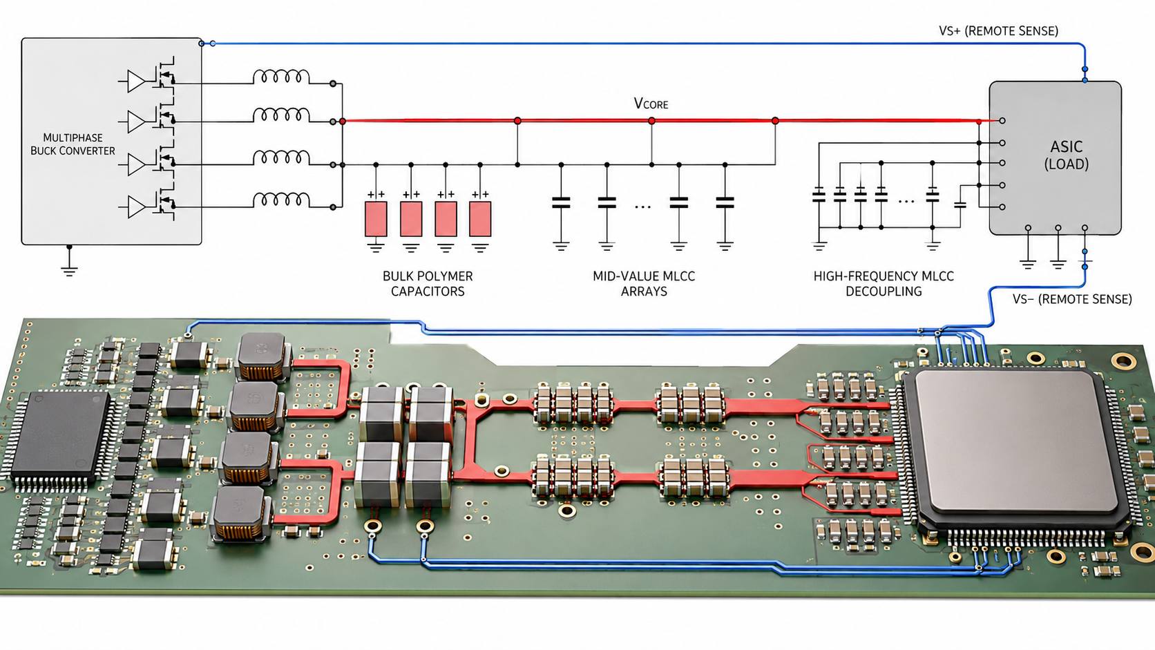
| Network Location | Typical Capacitor Role | Layout Priority |
|---|---|---|
| Converter output | Output ripple filtering, control-loop stability, lower-frequency transient support | Short return path to power stages and inductors, wide copper, low loop area |
| Power distribution area | Impedance reduction along the Vcore plane | Low-inductance connection to planes and balanced current spreading |
| ASIC side | High-speed local transient current support | Shortest practical path to ASIC power and ground pins |
| Remote sense area | Helps stabilize the regulated point seen by the controller | Clean sense routing, no shared high-current path, proper Kelvin connection |
| Test access area | Enables waveform, ripple, and transient validation | Low-inductance probing points at converter and load-side locations |
Bulk Capacitors and Polymer Capacitors
Bulk capacitors provide energy over lower-frequency load changes and help reduce rail movement before the control loop fully responds. In high-current Vcore rails, polymer capacitors are often used because they can offer low ESR, high ripple-current capability, and stable performance compared with many traditional electrolytic options.
Bulk capacitance should not be selected by capacitance value alone. Ripple current, ESR, voltage rating, temperature rating, lifetime, package height, board space, mounting method, and airflow all affect whether the capacitor can survive in a dense power-stage region.
| Bulk / Polymer Parameter | Why It Matters |
|---|---|
| Capacitance | Supports lower-frequency load energy and reduces large-signal rail movement. |
| ESR | Affects transient voltage step, damping, ripple heating, and impedance profile. |
| Ripple current rating | Determines whether the capacitor can handle AC current without overheating. |
| Lifetime rating | Important near hot inductors, smart power stages, and constrained airflow paths. |
| Voltage derating | Improves reliability margin and reduces stress under transients. |
| Mechanical height | May constrain placement near heat sinks, airflow ducts, mezzanine cards, or ASIC packages. |
MLCC Decoupling and Effective Capacitance
MLCCs are widely used in ASIC Vcore rails because they provide low impedance in compact packages and can be placed close to the load. However, the value printed in a BOM is the nominal value under specified test conditions, not necessarily the effective capacitance under real DC voltage, temperature, aging, and mounting conditions.
Murata describes DC bias characteristic as the phenomenon where effective electrostatic capacitance changes, usually decreases, when DC voltage is applied to high dielectric constant MLCCs. Murata also notes that designers should not accept catalog capacitance without considering the voltage conditions in the actual power line. (Murata, Voltage Characteristics of Electrostatic Capacitance)
TDK similarly notes that Class II dielectrics such as X7R and X5R can show capacitance decrease with applied voltage, while C0G behavior is comparatively flat. (TDK, MLCC DC Bias FAQ)
For early screening, the MLCC DC Bias Calculator can estimate effective capacitance from nominal capacitance, dielectric type, package size, rated voltage, applied voltage, or manufacturer curve data. It should not replace manufacturer-specific DC bias curves, but it is useful for detecting obviously weak capacitor choices before layout review.
MLCC DC Bias in Practical Decoupling Design
DC bias is especially important when replacing MLCCs in an existing high-current rail. A part with the same nominal capacitance, same rated voltage, and same case size may still have a different capacitance retention curve. That difference can change target impedance, load-step droop, and local decoupling margin.
The video below provides a concise visual reference for how DC bias affects multilayer ceramic capacitors.
ESR, ESL and Self-Resonant Frequency
A capacitor behaves as a capacitor only below its self-resonant region. Near self-resonance, impedance reaches a minimum that is strongly affected by ESR. Above self-resonance, ESL dominates and the capacitor behaves more inductively. This is why several capacitor values and package sizes are often used together in ASIC decoupling networks.
The MLCC Impedance Calculator can estimate capacitive reactance at a given frequency. For resonance review, the MLCC Self-Resonant Frequency Calculator can estimate SRF from capacitance and ESL, with ESR used to understand the minimum impedance region.
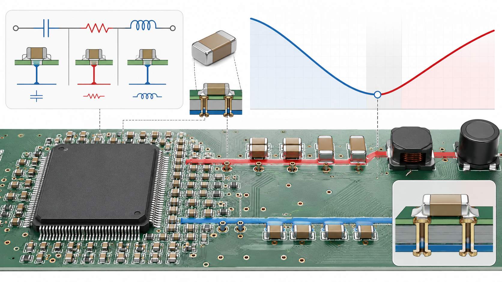
| Parameter | Effect on Vcore Rail | Selection Note |
|---|---|---|
| Effective capacitance | Sets stored charge and low-to-mid frequency impedance | Use DC bias and temperature-adjusted capacitance, not only nominal value. |
| ESR | Affects damping, ripple heating, and impedance near resonance | Very low ESR is not always automatically better if damping becomes insufficient. |
| ESL | Limits high-frequency transient current delivery | Package size, pad geometry, vias, and mounting location influence effective ESL. |
| SRF | Defines the frequency region where the capacitor reaches its lowest impedance | Use multiple values and packages to cover a wider impedance range. |
| Mounting inductance | Can dominate high-frequency behavior even when the MLCC itself is suitable | Use short connections, close vias, and direct power-ground plane access. |
Package Size and Placement: 0402, 0603, 1206 and 1210
MLCC case size affects capacitance availability, voltage rating, DC bias behavior, ESL, solder-joint robustness, placement density, and assembly yield. Smaller packages often have lower mounting inductance and can be placed closer to the ASIC, but high capacitance in a very small package may show stronger effective capacitance loss. Larger packages can provide higher nominal capacitance, but their high-frequency behavior and physical distance from the load must still be checked.
The MLCC Case Size Converter can help convert common EIA and metric package codes, such as 0402 to 1005, 0603 to 1608, 0805 to 2012, and 1206 to 3216, when reviewing BOMs, datasheets, and alternate part options.
| Package Size | Typical Strength | Design Caution |
|---|---|---|
| 0402 | Compact, low mounting inductance, useful near ASIC pins | Limited capacitance, harder inspection, stronger sensitivity to handling and assembly variation |
| 0603 | Good balance of size, capacitance range, and manufacturability | Placement and via connection still dominate high-frequency effectiveness |
| 0805 | Higher capacitance and voltage options than smaller packages | May be less effective for very high-frequency local decoupling if placed far from the load |
| 1206 / 1210 | Useful for larger capacitance values and lower-frequency support | Higher mounting area, possible mechanical stress, and less ideal high-frequency placement |
| Polymer SMD package | High capacitance, low ESR, high ripple current capability | Height, thermal stress, lifetime, polarity, and ripple current must be checked |
ASIC-Side Decoupling and Remote Sense Interaction
ASIC-side decoupling is placed close to the load because the regulator-side capacitors cannot instantly supply every high-frequency current edge through board planes, vias, socket structures, package inductance, and connector paths. Local capacitors reduce voltage movement at the ASIC power pins during the earliest part of a load transient.
Remote sense must be coordinated with the capacitor network. If the converter senses at the wrong location, it may regulate a point that does not represent the ASIC rail during transient load events. Sense traces should avoid high-current paths, switching nodes, and noisy return loops. Kelvin sensing should be routed to the intended load-side rail and ground reference.
| Placement Issue | Effect on Transient Response | Practical Check |
|---|---|---|
| Capacitors too far from ASIC | Plane and via inductance delay current delivery | Review distance from capacitor pads to ASIC power pins and planes. |
| Too few ground vias | Increases return inductance and rail bounce | Use low-inductance via access to power and ground planes. |
| Remote sense routed with power current | Creates measurement error and regulation instability risk | Route sense as a clean pair with controlled return reference. |
| Capacitors clustered only at regulator | Improves converter output but may not protect ASIC-side high-frequency transients | Distribute capacitors according to current path and frequency function. |
| Poor probe location | May hide load-side droop or exaggerate converter-side ripple | Measure at converter output, capacitor bank, and ASIC sense point. |
Dynamic Load Response and Output Capacitance
Output capacitors are selected to support current while the regulator control loop responds, but capacitors alone do not define dynamic response. Power-stage speed, controller compensation, phase count, inductor value, output impedance, layout parasitics, and sense placement all influence the load-step waveform.
TI's PMP21887 test report shows why dynamic testing matters. In one reported test, a 100 A load step was applied on top of a 300 A static load, with about 31 mV peak undershoot, 67 ns rise time, approximately 1200 A/µs load slew rate, and settling within less than 10 mV of the initial value in 2 µs.
| Load-Step Metric | Capacitor-Related Meaning |
|---|---|
| Peak undershoot | Shows immediate rail droop after load current increases; affected by capacitance, ESR, ESL and placement. |
| Peak overshoot | Shows rail rise after load release; affected by control response and output energy storage. |
| Slew rate | Fast current edges stress local MLCCs and mounting inductance before bulk capacitance can respond. |
| Settling time | Shows how quickly the regulator and capacitor network return the rail to the operating window. |
| Ringing | May indicate PDN resonance, insufficient damping, or poor measurement setup. |
Capacitor Substitution Risk in High-Current Vcore Rails
Capacitor substitution is risky in high-current ASIC rails because the replacement can change effective capacitance, ESR, ESL, self-resonant frequency, ripple-current capability, temperature behavior, lifetime, and mechanical reliability. Even when the capacitance, voltage rating, and package size appear similar, the impedance profile may not be equivalent.
| Substitution Item | Must Match or Be Revalidated | Risk if Ignored |
|---|---|---|
| Nominal capacitance | Capacitance value and tolerance | Stored energy and impedance may shift. |
| Effective capacitance | DC bias curve, temperature behavior, aging | Real capacitance may be lower than expected. |
| Dielectric | X5R, X6S, X7R, X7S, C0G, or other material class | Bias, temperature, and aging behavior may change. |
| Package size | EIA/metric dimensions, height, land pattern compatibility | Assembly fit, ESL, and placement may change. |
| ESR and ESL | Impedance curve or simulation model | PDN resonance and transient response may shift. |
| Ripple-current rating | Relevant mainly for polymer and bulk capacitors | Overheating or lifetime reduction may occur. |
| Manufacturer series | Part-specific curves, reliability ratings, termination style | Same value from another series may not behave the same. |
| Qualification level | Automotive, industrial, high-reliability, or standard grade requirement | Reliability and compliance mismatch may occur. |
Measurement and Validation Checklist
Capacitor selection should be validated by simulation and hardware measurement. A BOM-level capacitance check is only an early step. Final validation should include load-step testing, output ripple measurement, thermal measurement, and measurement at multiple rail locations.
| Validation Step | What to Measure | Why It Matters |
|---|---|---|
| DC output voltage | Vcore at converter output and ASIC sense point | Confirms regulation point and board voltage drop. |
| Ripple voltage | Switching ripple with low-inductance probing | Confirms capacitor and layout performance under switching operation. |
| Load-step response | Undershoot, overshoot, recovery time, ringing | Confirms transient behavior under ASIC-like load changes. |
| Temperature rise | Polymer capacitors, MLCC clusters, inductors, power stages | Identifies ripple heating and airflow problems. |
| Impedance profile | PDN impedance versus frequency by simulation or measurement | Identifies anti-resonance peaks and frequency coverage gaps. |
| Alternate part verification | Waveform and thermal comparison against approved BOM part | Prevents substitution from silently changing rail performance. |
Engineering Selection Workflow
A practical output capacitor workflow starts with target rail requirements and ends with physical validation. The order matters because a capacitor network selected only from nominal value can become unstable, too hot, physically unplaceable, or ineffective at the actual ASIC load point.
- Define Vcore nominal voltage, tolerance window, load current, peak current, and transient profile.
- Estimate target impedance from allowed voltage droop and load-step current.
- Separate the capacitor network into bulk, polymer, mid-value MLCC, small MLCC, and ASIC-side decoupling roles.
- Use effective capacitance after DC bias, temperature, aging, and tolerance rather than nominal capacitance alone.
- Check ESR, ESL, self-resonant frequency, and impedance interaction across frequency.
- Place capacitors according to current path, not only available board space.
- Coordinate capacitor placement with remote sense routing and measurement points.
- Validate output ripple, load-step response, overshoot, undershoot, recovery time, and thermal behavior.
- Control approved alternates using DC bias curves, impedance curves, package, height, ripple-current rating, and qualification requirements.
Frequently Asked Questions
Why are output capacitors important in ASIC Vcore rails?
They provide local transient current, reduce rail impedance, control ripple, support converter stability, and reduce voltage droop during fast ASIC load changes.
Can I select output capacitors only by total capacitance?
No. Effective capacitance, ESR, ESL, self-resonant frequency, DC bias, temperature, placement, current path, and control-loop interaction must also be checked.
Why does MLCC DC bias matter?
Class II MLCCs such as X5R and X7R can lose effective capacitance under applied DC voltage. The operating capacitance may be significantly lower than the nominal BOM value.
Why use multiple capacitor values?
Different capacitor values and package sizes provide lower impedance in different frequency regions. A layered network can cover a wider transient and noise spectrum than one large capacitor type.
Are polymer capacitors still needed if many MLCCs are used?
Often yes. Polymer capacitors can support lower-frequency energy demand, provide useful ESR damping, and handle ripple current that MLCC arrays may not address alone.
What is the risk of replacing an MLCC with the same capacitance and voltage rating?
The replacement may have different DC bias behavior, ESR, ESL, package height, impedance curve, dielectric characteristics, and reliability rating. It should be revalidated.
Where should ASIC-side decoupling capacitors be placed?
They should be placed as close as practical to the ASIC power and ground pins or connected to low-inductance power and ground planes near the load-side current path.
How do I validate an output capacitor network?
Use load-step testing, ripple measurement, thermal measurement, PDN simulation or impedance measurement, and comparison at the converter output, capacitor bank, and ASIC remote sense point.
Engineering Summary
Output capacitor selection for high-current ASIC Vcore rails requires a network-based approach. Bulk capacitors, polymer capacitors, mid-value MLCCs, small MLCCs, and ASIC-side decoupling each support a different part of the power-delivery problem. The final design must control impedance, transient droop, ripple, resonance, thermal stress, and placement-related inductance.
A reliable capacitor strategy uses effective capacitance rather than nominal capacitance, checks DC bias curves, reviews ESR and ESL, compares package size and self-resonant behavior, coordinates remote sense placement, and validates the result with load-step waveforms. In high-current Vcore rails, capacitor substitution should be treated as an engineering change, not a simple BOM swap.


