
 My Inquiry
 My Account


High-Current ASIC Core Power Supply Design: 12-Phase Buck, PMBus and Dynamic Load Response
Article Details
High-current ASIC core power rails are difficult because they combine very low voltage, very high current, fast load transients, tight voltage tolerance, high thermal density and complex monitoring requirements. A core rail near 0.8 V to 1.0 V may need hundreds of amperes, and the allowable voltage deviation during a fast load step can be only a small fraction of the nominal rail voltage.
Multiphase buck converters are commonly used for these rails because one power stage cannot efficiently deliver the full current alone. By spreading current across multiple phases, the design can reduce per-phase current stress, distribute heat, reduce ripple and improve transient response. PMBus control, remote sense, output capacitor placement and power-stage layout become part of the same design problem.
Texas Instruments PMP21887 is a useful reference case for this design class. TI positions it as a 12-phase PMBus buck converter for datacenter hardware accelerator, enterprise switch and router ASIC core rails, with 0.85 V nominal output, 360 A continuous current and 600 A peak current.
What Defines a High-Current ASIC Core Power Supply?
A high-current ASIC core power supply converts a system input bus, such as 12 V, into a low-voltage high-current rail for an ASIC, FPGA, accelerator, switch chip or processor core. The design must maintain the required core voltage during static load, fast load step, load dump, startup, fault and thermal conditions.
| Design Area | Why It Matters |
|---|---|
| Core voltage accuracy | The ASIC rail may have a narrow operating window, so output regulation and remote sense accuracy are critical. |
| Continuous current | The regulator must support steady compute, switching or packet-processing current without overheating. |
| Peak current | The rail must survive short current bursts without excessive voltage droop or power-stage stress. |
| Load-step response | Fast ASIC activity changes can cause undershoot, overshoot and recovery-time problems. |
| Output capacitor network | Bulk capacitors, MLCCs and ASIC-side decoupling support different frequency ranges and current paths. |
| PMBus telemetry | Digital monitoring helps with margining, fault reporting, manufacturing test and system health tracking. |
| Thermal distribution | Losses are spread across power stages, inductors, copper planes and airflow paths. |
PMP21887 as a Reference Case
PMP21887 is useful because it is not only a schematic example. It includes a tested 12-phase architecture, PMBus control, smart power stages, a high-current output rail and an onboard dynamic load used to evaluate fast load response. TI's test report lists an input voltage range of 10 V to 14 V DC, output range of 0.8 V to 1.2 V DC, testing at a 0.85 V setting and maximum load current of 360 A static / 600 A peak.
| Reference Design Item | Relevant Engineering Meaning |
|---|---|
| 12-phase buck topology | Current is distributed across multiple phases instead of forcing one stage to handle the full load. |
| 0.85 V nominal Vcore | Low-voltage rails are sensitive to millivolt-level undershoot, overshoot and remote-sense placement. |
| 360 A continuous / 600 A peak capability | Both thermal operating point and short-duration current behavior must be checked. |
| Twelve CSD95480 70 A smart power stages | Each phase uses an integrated smart power stage, reducing discrete driver/MOSFET implementation complexity. |
| PMBus controller architecture | Digital configuration, monitoring, margining and manufacturing test workflows can be supported. |
| Onboard dynamic load | Fast transient testing can be performed near the power stage and output capacitor network. |
Why 0.85 V at Hundreds of Amps Is Difficult
A high-current ASIC core rail is not difficult only because of current magnitude. The harder problem is maintaining a low-voltage rail through fast current changes while keeping power loss, temperature, ripple, voltage error and layout parasitics under control.
At 0.85 V, a 30 mV transient event is already a meaningful percentage of the rail. Large current steps can also create voltage error through output capacitor ESR, capacitor ESL, plane inductance, via inductance, power-stage delay, control-loop behavior and remote-sense routing. Increasing capacitor quantity may reduce some impedance regions, but it cannot correct every limitation caused by control response, placement, package inductance or current-loop geometry.
12-Phase Buck Architecture and Current Sharing
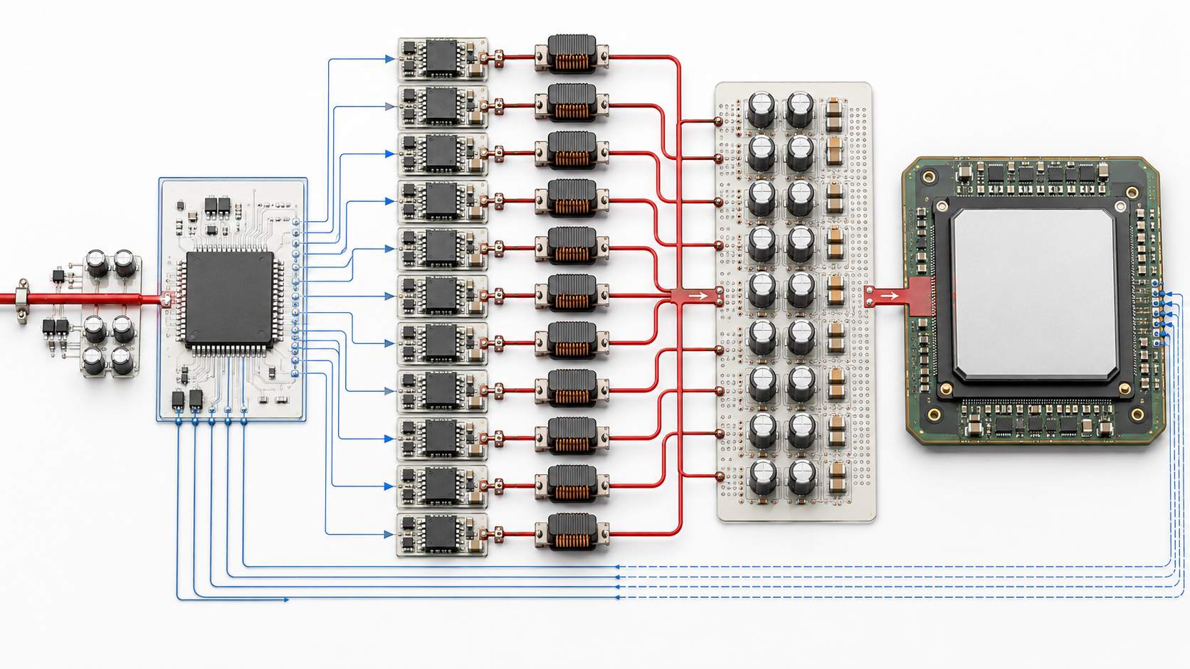
A 12-phase buck converter divides the load current across 12 interleaved phases. Each phase typically includes a PWM control signal, smart power stage or driver/MOSFET pair, inductor, current-sense path and local layout region. Interleaving the phases reduces effective ripple frequency seen by the input and output networks and helps distribute heat across a larger board area.
TI's PMP21887 product page lists TPS536C7 as the multiphase PMBus PWM controller and CSD95480RWJ as the 70 A synchronous buck smart power stage used in the design. The PMP21887 schematic also shows APWM and current-sense connections across the multiphase control section.
| Multiphase Design Check | Engineering Purpose |
|---|---|
| Phase count | Sets per-phase current, ripple cancellation opportunity and controller complexity. |
| Current sharing | Prevents one phase from overheating or saturating its inductor earlier than the others. |
| Phase interleaving | Reduces effective ripple and spreads switching events across time. |
| Inductor selection | Controls ripple current, saturation margin, DCR loss and transient response. |
| Power-stage placement | Affects copper loss, thermal distribution and loop inductance. |
| Sense routing | Impacts current reporting, voltage regulation point and load-line behavior. |
PMBus Control, Margining and Remote Sense
PMBus is valuable in high-current ASIC rails because the regulator is not only a fixed-output power block. It may need digital voltage adjustment, telemetry, fault reporting, temperature monitoring, current reporting, margin testing, sequencing and manufacturing script support.
Remote sense is equally important. At hundreds of amperes, even a small resistance or inductance between the regulator and ASIC can create measurable voltage error. Sensing the voltage at the correct load point helps the controller regulate the rail where the ASIC actually receives power, not only at the converter output capacitor bank.
| PMBus / Sense Feature | Why It Matters in ASIC Core Rails |
|---|---|
| Voltage margining | Supports production test, guard-band validation and ASIC rail tolerance checks. |
| Current telemetry | Helps monitor per-rail loading and detect abnormal consumption. |
| Temperature telemetry | Supports thermal protection, airflow validation and field diagnostics. |
| Fault reporting | Improves debug of overcurrent, undervoltage, overvoltage and thermal events. |
| Remote sense | Compensates board voltage drop between regulator output and ASIC load point. |
| Manufacturing access | Allows programming, margin checks and automated test through a controlled interface. |
Dynamic Load Response: The Real Test of a Vcore Rail
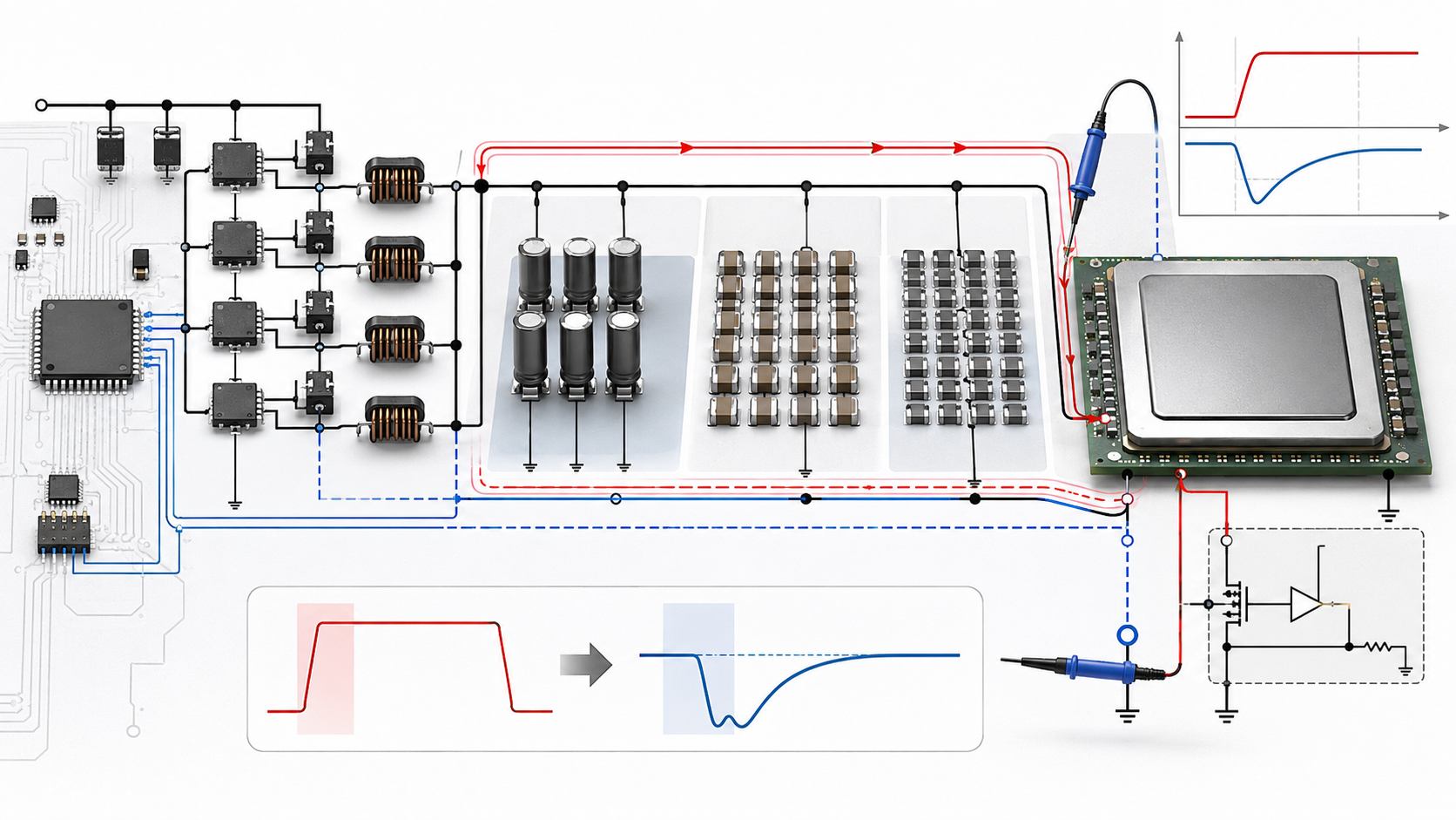
Static current capability does not prove that an ASIC core rail is ready for production. High-speed ASICs can create fast current steps when internal logic, SerDes blocks, memory interfaces or acceleration engines change activity. The regulator must respond before the core voltage falls outside the allowed window.
TI's PMP21887 test report includes a 100 A load step applied on top of a 300 A static load. The reported short-term response shows about 31 mV peak undershoot, a 67 ns 10%–90% rise time, approximately 1200 A/µs load slew rate and output settling within less than 10 mV of the initial value in 2 µs.
| Dynamic Test Metric | What It Shows |
|---|---|
| Load step amplitude | How much current changes during the event. |
| Slew rate | How fast the current changes; faster edges stress local capacitance and control response. |
| Peak undershoot | Lowest rail voltage after a load increase. |
| Peak overshoot | Highest rail voltage after a load release or load dump. |
| Settling time | How long the rail takes to return near its original operating value. |
| Probe location | Determines whether the measurement reflects the regulator output, capacitor bank or ASIC sense point. |
Output Capacitor Network: Bulk, MLCC and ASIC-Side Decoupling
Output capacitance in high-current core rails is a frequency-domain network, not a single capacitor value. Bulk capacitors support lower-frequency energy demand, MLCCs reduce impedance at higher frequency, and ASIC-side capacitors address local package and board parasitics near the load.
The PMP21887 BOM shows a broad capacitor network, including polymer hybrid capacitors, 22 µF ceramic capacitors in 1206 and 1210 packages, 2.2 µF capacitors in 0402 and 0603 packages, 1000 pF capacitors, 0.1 µF capacitors and other local bypass values.
For a first-pass decoupling review, the Decoupling Capacitor Calculator can help estimate capacitance from load step, allowed voltage droop and response time. For frequency-domain impedance checks, the MLCC Impedance Calculator can be used to compare capacitance, ESR, ESL and frequency behavior before selecting package sizes and placement strategy.
| Capacitor Layer | Main Role | Design Risk |
|---|---|---|
| Bulk capacitor | Supports lower-frequency load energy and input/output rail stability. | Ripple current, ESR, lifetime, size and thermal stress must be checked. |
| Mid-value MLCC | Reduces mid-frequency impedance and supports transient current close to the regulator. | Effective capacitance may drop under DC bias; placement and loop path matter. |
| Small MLCC | Targets higher-frequency bypass and local current loops. | ESL, via placement and mounting inductance can dominate real behavior. |
| ASIC-side decoupling | Supplies current after board and package parasitics limit regulator-side response. | Mechanical constraints and power-pin distribution can restrict ideal placement. |
| Sense-point capacitor | Helps local rail stability near the regulated sense location. | Incorrect sense routing can create misleading voltage regulation behavior. |
Smart Power Stage and Inductor Selection
Smart power stages integrate driver and MOSFET functions into a compact power block, often with current and temperature reporting features. In a multiphase ASIC rail, the power stage must be evaluated by more than headline current rating. Switching loss, conduction loss, thermal pad design, airflow, transient current and phase balance all affect real operating margin.
Inductors are equally important. PMP21887 test conditions reference 12 inductors of 150 nH in the dynamic response section of the test report. Inductor value influences ripple current, transient response, saturation margin, DCR loss and current-sharing behavior.
For early buck-stage estimation, the Buck Converter Calculator can be used to check duty cycle, inductor value, ripple current, output power and input current before detailed simulation and vendor-specific loss modeling.
| Component | Critical Parameter | Why It Matters |
|---|---|---|
| Smart power stage | Current rating, thermal resistance, switching loss, package | Determines phase current capability and heat density. |
| Inductor | Inductance, saturation current, DCR, ripple current rating | Controls ripple, transient response and copper/core losses. |
| Input capacitor | RMS ripple current, ESR, placement, voltage rating | Supports pulsed switching current and reduces input rail stress. |
| Output capacitor | Effective capacitance, ESR, ESL, DC bias, placement | Controls transient droop, ripple and impedance profile. |
| Current sense path | Accuracy, routing symmetry, noise coupling | Supports current balance, telemetry and protection. |
Thermal Design and Efficiency Considerations
High-current core rails convert large amounts of power even at low output voltage. A rail delivering hundreds of amperes can move hundreds of watts to the load, while converter losses are distributed across smart power stages, inductors, capacitors, PCB copper, connectors and airflow paths.
Thermal review should include steady load, peak load duration, airflow direction, copper spreading, via arrays, power-stage placement, inductor heating and capacitor ripple current. TI's test report also notes the need for fan cooling above a certain high-current operating condition, which reinforces that bench validation must include airflow and temperature measurement, not only electrical waveforms.
| Thermal Area | Engineering Check |
|---|---|
| Power stage temperature | Measure hot spots across phases, especially phases far from airflow. |
| Inductor temperature | Check copper loss, core loss and saturation margin under load. |
| PCB copper | Review current density, via arrays, plane spreading and connector current paths. |
| Capacitor ripple | Check RMS current rating, ESR heating and lifetime derating. |
| Airflow condition | Validate in the intended enclosure and fan direction, not only on an open bench. |
Layout and Validation Checklist
At hundreds of amperes, layout is part of the power circuit. Schematic correctness is not enough. Converter performance depends on switch-loop geometry, input capacitor placement, output capacitor distribution, current return paths, sense routing, PMBus access, thermal copper and measurement points.
| Checklist Item | What to Verify |
|---|---|
| Input switching loop | Minimize loop area between input capacitor, power stage and return path. |
| Output current path | Use wide copper, low-impedance planes and balanced routing to the load. |
| Remote sense routing | Route as a clean differential sense pair to the correct load point. |
| Phase symmetry | Reduce layout imbalance that can disturb current sharing or thermal distribution. |
| Capacitor placement | Place bulk, mid-frequency and local MLCC capacitors according to current-path function. |
| Probe points | Provide test locations for Vcore, current, PMBus, enable, fault, power-good and dynamic load response. |
| Thermal path | Use copper, vias and airflow to remove heat from power stages and inductors. |
| Manufacturing access | Provide PMBus or programming access for margining and fault-log review. |
Component Selection Notes for Engineering and Procurement
High-current ASIC rails require component selection from electrical, thermal and supply-chain viewpoints. A substituted capacitor, inductor or power stage may fit the footprint but still change transient response, ripple, temperature rise or current sharing.
| Component Group | Parameters to Check | Substitution Risk |
|---|---|---|
| PMBus controller | Phase count, control mode, telemetry, margining, fault handling, sense method | Control-loop behavior and PMBus compatibility may change. |
| Smart power stage | Current rating, package, thermal resistance, reporting features, switching performance | Losses, phase current margin and telemetry behavior may change. |
| Inductor | Inductance, Isat, DCR, RMS current, size, shielding, thermal rating | Ripple current, transient response, heat and saturation margin can shift. |
| MLCC | Capacitance, voltage rating, dielectric, DC bias, ESR, ESL, case size | Effective capacitance and impedance profile may differ from nominal value. |
| Polymer / bulk capacitor | Capacitance, ESR, ripple current, lifetime, temperature rating, package | Low-frequency transient support and heating can change. |
| Sense and feedback resistors | Tolerance, temperature coefficient, routing, power rating | Voltage accuracy, telemetry and margining may be affected. |
| Connectors and test points | Current rating, signal integrity, PMBus access, mechanical durability | Debug, manufacturing test and field diagnostics may become harder. |
Frequently Asked Questions
Why use a 12-phase buck converter for an ASIC core rail?
A 12-phase buck converter spreads load current across multiple power stages and inductors. This reduces per-phase current stress, improves thermal distribution and helps manage ripple and transient response.
What is PMBus used for in ASIC power rails?
PMBus supports digital configuration, voltage margining, telemetry, fault reporting, manufacturing test and system-level monitoring of high-current power rails.
Why is dynamic load response important?
ASIC current can change very quickly during workload transitions. Dynamic load response shows whether the regulator can prevent excessive voltage undershoot, overshoot and recovery delay.
Why is output capacitance not only a bulk capacitor decision?
Different capacitors support different frequency ranges and current paths. Bulk capacitors, MLCCs and ASIC-side decoupling must be placed and selected as a complete impedance network.
What does smart power stage selection affect?
It affects current capability, switching loss, conduction loss, thermal density, telemetry and phase current margin.
What should be checked when replacing MLCCs in a high-current rail?
Check package size, capacitance, voltage rating, dielectric, DC bias derating, ESR, ESL, temperature rating and placement function.
Can a TI reference design be copied directly into production?
It should be treated as an engineering reference. Production hardware still requires validation for layout, airflow, load profile, component derating, transient response, reliability and regulatory requirements.
What is the most important test for a high-current ASIC Vcore rail?
Static load testing, thermal testing and efficiency testing are necessary, but fast load-step testing is especially important because it shows voltage droop, overshoot and recovery behavior under realistic transient stress.


