
 My Inquiry
 My Account


How to Use a Voltage Tester: AC/DC, Battery, and Voltage Divider Checks
Article Details
Voltage testing is a fundamental skill for electricians, engineers, technicians, and electronics hobbyists. Accurate voltage measurement ensures safe operation, prevents equipment damage, and verifies that devices are performing correctly. A voltage tester may be a non-contact voltage tester, a voltage tester pen, a contact voltage tester, or a digital multimeter, each suited to different applications.
Understanding the differences between tester types and knowing how to measure voltage correctly is essential for both AC and DC circuits, batteries, PCB power rails, and low-voltage electronics. In addition, calculating expected deviations and verifying test points helps engineers make reliable decisions.
Types of Voltage Testers
Voltage testers can be categorized based on how they detect voltage and the information they provide:
- Non-contact voltage tester: Detects AC voltage presence without touching exposed conductors. Useful for preliminary checks before working on wires or outlets.
- Voltage tester pen: Pen-style, usually non-contact, indicates the presence of voltage and can highlight wiring without direct probe contact.
- Contact voltage tester: Requires touching conductors with probes to confirm voltage.
- Digital multimeter: Measures AC/DC voltage numerically, along with current, resistance, and continuity. Ideal for precise measurements.
- Battery voltage tester: Designed to check battery terminals and power source outputs accurately.

For a non-contact voltage tester, it is important to know that they are excellent for detecting AC voltage presence, but they may not indicate the exact voltage value. For example, a wire showing as "live" does not reveal if the voltage is 110V, 120V, 220V, or 240V. (Fluke, Non-Contact Voltage Detector Basics)
Using a Multimeter for Voltage Measurement
A digital multimeter is the preferred tool when a numeric voltage reading is required. For DC voltage measurement, set the meter to DC mode, connect the black lead to ground and the red lead to the test point, and read the value. For AC voltage measurement, set to AC mode and measure across the two terminals. This method provides precise readings and allows engineers to evaluate whether the voltage is within expected tolerances. (Keysight, Using a Digital Multimeter)
Checking Whether a Voltage Reading Is Within Tolerance
A voltage reading is only useful when it is compared with an expected value. In electronics testing, a measured voltage may still be acceptable if it stays inside the specified tolerance range. For example, a 5V rail with ±5% tolerance should normally stay between 4.75V and 5.25V.
| Nominal Voltage | Allowed Tolerance | Acceptable Range |
|---|---|---|
| 3.3V | ±5% | 3.135V to 3.465V |
| 5V | ±5% | 4.75V to 5.25V |
| 12V | ±10% | 10.8V to 13.2V |
When checking low-voltage circuits, batteries, adapters, or PCB power rails, a Voltage Tester Calculator can be used after measurement to compare the actual reading with the nominal voltage and allowed tolerance. This is useful when the tester shows a numerical value, but the technician still needs to decide whether the deviation is acceptable.
For example, if a 5V rail measures 4.82V, it is still within a ±5% tolerance range. If the same rail measures 4.62V, the reading is outside that range and may indicate excessive voltage drop, overload, weak regulation, poor wiring, or a failing power source.
Battery Voltage Testing
Battery-powered devices require careful voltage measurement to avoid premature failures. Measuring battery voltage under load is important because an unloaded battery may appear healthy but drop sharply under current draw. A voltage tester, together with a multimeter and the Voltage Tester Calculator, ensures accurate verification of battery health and supply stability.
Voltage Drop Testing
Voltage drop testing determines how much voltage is lost across wiring, connectors, switches, or PCB traces while current is flowing. A significant voltage drop indicates resistance or connection problems that may affect circuit operation. This test is common in automotive wiring, low-voltage electronics, and industrial circuits.
Voltage drop can be calculated using expected current and conductor resistance, but real-world verification often requires measurement with a voltage tester or multimeter. Proper interpretation ensures safe and reliable operation of devices.
Voltage Divider and Test Point Measurements
Many electronic circuits use resistor dividers to create feedback voltages, ADC inputs, battery sensing nodes, reference levels, or diagnostic test points. A divider may look simple on the schematic, but the measured voltage can change when the test point is connected to a load or measurement instrument.
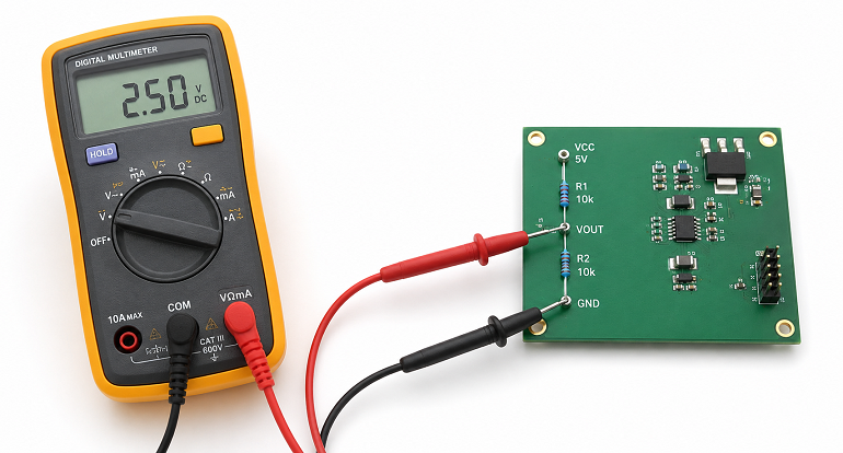
The ideal divider output is usually calculated as:
VOUT = VIN × R2 / (R1 + R2)
In real circuits, the input impedance of the next stage, ADC leakage, probe impedance, or an unexpected parallel path can pull the test point away from the ideal value. This is why a measured divider voltage should not be judged only by the printed resistor values.
For resistor divider checks, feedback network verification, battery monitoring circuits, and ADC input test points, a Voltage Divider / Test Point Calculator can help estimate the expected test point voltage and the deviation caused by load resistance. This makes it easier to compare the measured value from a multimeter with the value the circuit should produce under real conditions.
For example, if a divider is designed to output 2.5V but the measured test point is only 2.2V, the issue may not be the power supply itself. It may be caused by load resistance, wrong resistor values, leakage, meter input impedance, or another circuit node pulling the divider output down.
Using the calculator helps engineers anticipate changes under load, verify ADC reference points, and ensure that voltage levels remain within specification, reducing potential errors during testing.
How to Use a Voltage Tester Safely
- Always assume the circuit is live and use rated testers.
- Check the instrument before and after use with a known voltage source.
- Keep fingers behind probe guards and avoid direct contact with exposed conductors.
- Do not rely solely on non-contact testers for critical verification.
- Verify DC and AC voltages with appropriate modes on multimeters or tester pens.
Common Mistakes in Voltage Testing
- Using non-contact testers for precise voltage measurements.
- Testing DC circuits with AC-only pens.
- Measuring voltage without proper ground reference.
- Ignoring expected voltage tolerances.
- Failing to check voltage under load or at resistor test points.
Practical Voltage Testing Checklist
- Choose a voltage tester suitable for the voltage range and environment.
- Use non-contact testers for quick AC presence detection.
- Use a multimeter for precise AC/DC measurement, battery testing, and voltage drop analysis.
- Verify battery voltage under load for accurate assessment.
- Check voltage drops across wiring and components.
- Calculate expected voltage at divider and test points using a professional calculator.
By following these procedures, engineers and technicians can accurately determine circuit voltages, verify component performance, ensure power supply stability, and troubleshoot effectively, reducing errors and increasing safety in AC/DC, battery-powered, and low-voltage electronics systems.


