
 My Inquiry
 My Account


MLCC Ripple Current and ESR: How to Calculate Heating
Article Details
MLCCs are widely used in power supply circuits, DC-DC converters, decoupling networks, RF filters, automotive modules, industrial controllers, and high-density digital hardware. Their low ESR, compact size, and good high-frequency behavior make them useful in many designs. However, low ESR does not mean zero loss.
When ripple current flows through an MLCC, part of the electrical energy is converted into heat. In most low-power circuits, this heating is small. In switching regulators, pulsed loads, high-current decoupling networks, and high-frequency power rails, ESR-related heating can become an important reliability issue.
This guide explains how MLCC ESR, ripple current, RMS current, duty cycle, and power dissipation affect capacitor temperature rise. It also explains why MLCC heating is not always obvious from the schematic and how engineers can reduce the risk of long-term capacitor stress.
What ESR Means in an MLCC
ESR stands for equivalent series resistance. It represents the small resistive loss inside a real capacitor. An ideal capacitor would store and release energy without loss, but a real multilayer ceramic capacitor has internal electrode resistance, termination resistance, dielectric loss, and frequency-dependent behavior.
In simple terms, ESR is the part of the capacitor that turns ripple current into heat.
The basic relationship is:
Power Loss = IRMS2 × ESR
Where IRMS is the RMS ripple current through the capacitor and ESR is the equivalent series resistance at the operating frequency.
| Parameter | Meaning | Why It Matters |
|---|---|---|
| ESR | Equivalent series resistance of the MLCC | Determines resistive power loss |
| Ripple current | AC current flowing through the capacitor | Higher ripple current increases heating |
| RMS current | Effective heating value of the ripple current | Used for dissipation calculation |
| Frequency | Operating or switching frequency | ESR and impedance change with frequency |
MLCC ESR is usually much lower than the ESR of aluminum electrolytic capacitors. This is one reason MLCCs are preferred for high-frequency decoupling. But in high-current applications, even a few milliohms can produce measurable heat.
Why Ripple Current Causes MLCC Heating
Ripple current is the AC component of current that flows in and out of a capacitor. In a switching power supply, the output capacitors absorb pulsed current from the inductor and help smooth the output voltage. In a high-speed digital circuit, decoupling capacitors deliver short bursts of current during fast load transitions.
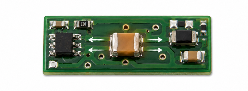
When this ripple current flows through ESR, heat is generated inside the capacitor body and terminations. The power loss rises with the square of the RMS current, which means a small increase in ripple current can cause a much larger increase in heat.
For example:
| RMS Ripple Current | ESR | Estimated ESR Loss |
|---|---|---|
| 0.5A | 10mΩ | 0.0025W |
| 1.0A | 10mΩ | 0.01W |
| 2.0A | 10mΩ | 0.04W |
| 3.0A | 10mΩ | 0.09W |
The numbers may look small, but MLCCs are physically tiny. A small amount of heat concentrated in a compact ceramic body can still create local temperature rise, especially when several capacitors are placed near hot power components.
Where ESR Heating Matters Most
MLCC ESR heating is usually most important in circuits with high ripple current, high switching frequency, or repeated pulsed operation. It is less important in simple timing, low-frequency filtering, or very light-load applications.
Common high-stress applications include:
- DC-DC converter input capacitors
- DC-DC converter output capacitor banks
- high-current GPU and CPU power rails
- automotive power modules
- motor control electronics
- RF power circuits
- pulsed load and burst-current circuits
- industrial switching power supplies
In these applications, MLCCs are not only passive voltage smoothing parts. They become part of the power delivery path and may carry significant RMS ripple current.
Using an MLCC ESR Dissipation Calculator
In practical design work, ESR heating should be checked before the capacitor bank is finalized. The key inputs are normally RMS ripple current, ESR, and operating duty condition. If ripple current is shared across multiple MLCCs in parallel, the current distribution also needs to be considered.
An MLCC ESR Dissipation Calculator can help estimate power dissipation from RMS current and ESR. This is useful when comparing MLCC options for switching regulators, pulsed loads, power rail decoupling, or high-frequency capacitor banks.
The calculation does not replace thermal testing on the final PCB, but it provides a practical early warning. If the estimated dissipation is already high, the design may need more capacitors in parallel, a lower-ESR part, a larger case size, better copper area, or a different capacitor technology.
RMS Current Is More Useful Than Peak Current
Peak current can look dramatic, but RMS current is usually more useful for heating analysis. ESR loss depends on the heating effect of current over time, not only the highest instantaneous current spike.
In a pulsed waveform, two signals may have the same peak current but very different heating impact if their duty cycles are different.
| Current Condition | Heating Risk | Reason |
|---|---|---|
| High peak, very low duty cycle | Moderate | Short pulse duration limits heating |
| Moderate current, high duty cycle | Higher | Current flows for more of the operating time |
| Continuous RMS ripple current | High if ESR or current is large | Heat is generated continuously |
This is why capacitor ripple current analysis should use RMS values whenever possible. For switching applications, the ripple waveform, duty cycle, and current sharing between capacitors all affect real dissipation.
MLCC ESR Changes With Frequency
MLCC ESR is not perfectly constant. It changes with frequency, capacitor construction, dielectric material, package size, capacitance value, and temperature. A value measured at one frequency may not represent behavior at another frequency.
This matters because switching power supplies and high-speed digital circuits do not operate at only one simple frequency. They may generate harmonic content, fast edges, and transient current components across a broad frequency range.
At low frequency, capacitive reactance dominates. Around the self-resonant region, impedance may reach a minimum. Above resonance, inductive behavior becomes more important. ESR is only one part of this impedance behavior, but it directly contributes to heat generation.
For reliable design, ESR should be checked at the relevant operating frequency range rather than copied from a generic datasheet table without context.
Parallel MLCCs and Current Sharing
Designers often place several MLCCs in parallel to reduce impedance, increase capacitance, and share ripple current. In theory, parallel capacitors divide the current. In practice, current sharing may not be perfectly equal.
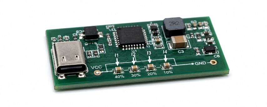
Current distribution depends on:
- capacitor ESR and ESL
- placement distance from the switching node or load
- PCB trace and plane impedance
- via placement
- package size and capacitance value
- frequency content of the ripple current
A capacitor placed closer to the high-current path may carry more ripple current than another capacitor farther away. This can lead to uneven heating inside a capacitor bank.
When many MLCCs are used around a VRM, processor, FPGA, or GPU rail, layout symmetry and current path design become important. The capacitor bank should be evaluated as a network rather than a simple sum of nominal capacitance values.
How ESR Heating Can Lead to MLCC Failure
ESR heating does not always cause immediate failure. More often, it contributes to long-term reliability degradation. Repeated heating and cooling cycles can add thermal stress to the ceramic body, solder joints, and terminations.
Potential consequences include:
- local temperature rise near the capacitor
- accelerated aging of surrounding materials
- solder joint fatigue
- reduced insulation resistance margin
- higher risk under vibration or board flex
- eventual cracking or electrical instability
In high-reliability products, capacitor temperature rise should be reviewed together with voltage derating, DC bias, mechanical stress, and PCB layout. ESR dissipation is only one part of MLCC reliability, but it is an important one in power electronics.
MLCC Heating vs Electrolytic Capacitor Heating
Electrolytic capacitors often have higher ESR than MLCCs, so their ripple current rating is usually discussed more directly. MLCCs have lower ESR, but their small size can make thermal concentration more important in high-density layouts.
| Capacitor Type | ESR Behavior | Heating Consideration |
|---|---|---|
| MLCC | Very low ESR, strong high-frequency performance | Small body can concentrate heat under high RMS current |
| Aluminum electrolytic | Higher ESR, stronger frequency and temperature dependence | Ripple current rating is usually a major datasheet limit |
| Polymer capacitor | Low ESR compared with traditional electrolytic | Often used where higher ripple current is required |
In many power supply designs, MLCCs and bulk capacitors are used together. MLCCs handle high-frequency decoupling, while polymer or electrolytic capacitors provide bulk energy storage. The best solution depends on ripple current, voltage, capacitance, temperature, board space, and impedance targets.
Common Mistakes in MLCC Ripple Current Design
Many MLCC heating problems come from treating ceramic capacitors as ideal components. They are excellent parts, but they still have real electrical and thermal limits.
Common design mistakes include:
- checking capacitance value but ignoring RMS ripple current
- using ESR values from the wrong frequency range
- assuming current divides equally across parallel MLCCs
- placing one capacitor too close to a hot switching component
- using smaller packages without checking thermal concentration
- ignoring duty cycle in pulsed applications
- focusing only on voltage rating while missing ripple heating
These mistakes may not appear during a short bench test. They often show up after thermal cycling, high-load operation, field use, or operation inside a sealed enclosure.
How to Reduce MLCC ESR Heating
Reducing MLCC ESR heating usually requires a combination of part selection, layout improvement, and current distribution control.
- Use capacitors with lower ESR at the relevant frequency range.
- Use multiple MLCCs in parallel to share ripple current.
- Check current sharing rather than assuming equal distribution.
- Use adequate copper area to spread heat.
- Avoid placing MLCCs too close to hot inductors, MOSFETs, or power ICs.
- Consider larger package sizes if thermal concentration is a concern.
- Evaluate polymer or electrolytic capacitors when bulk ripple current is high.
- Verify real temperature rise on the final PCB during load testing.
The best time to check ESR dissipation is before PCB layout is frozen. Once the capacitor footprint, placement, and copper layout are fixed, correcting ripple current heating may require a board revision.
Practical MLCC ESR Design Checklist
| Design Check | Why It Matters |
|---|---|
| Confirm RMS ripple current | Determines real heating effect |
| Check ESR at operating frequency | Datasheet values may vary with frequency |
| Calculate ESR dissipation | Identifies heating risk before layout release |
| Review capacitor placement | Affects current sharing and thermal exposure |
| Check capacitor bank layout | Parallel MLCCs may not share current equally |
| Measure final PCB temperature | Confirms real thermal behavior under load |
MLCC ESR heating is easy to overlook because ceramic capacitors are often described as low-loss components. In high-frequency and high-current designs, however, ripple current through ESR can still create meaningful power dissipation. Checking RMS current, ESR, frequency behavior, and capacitor placement helps prevent overheating, reliability loss, and late-stage power supply problems.


