
 My Inquiry
 My Account


Why MLCCs Get Damaged: Cracking, DC Bias and Failure Prevention
Article Details
MLCC damage is a common reliability problem in modern electronics, especially in compact PCB layouts, power supply circuits, automotive modules, industrial controllers, and high-density computing hardware. A multilayer ceramic capacitor may look simple from the outside, but its internal structure is made of many thin ceramic dielectric layers and metal electrodes. This structure gives MLCCs excellent electrical performance, but it also makes them sensitive to mechanical stress, electrical overstress, DC bias, thermal cycling, and poor replacement decisions.
In many field failures, the MLCC is not visibly burned or broken. The capacitor may have an internal crack, reduced effective capacitance, leakage current, intermittent short circuit behavior, or abnormal impedance at the operating frequency. This is why MLCC damage is often harder to diagnose than damage in larger electrolytic capacitors or visibly burned power components.
For engineers, buyers, and repair teams, the important point is that MLCC failure is rarely caused by only one factor. Package size, PCB bending, voltage margin, dielectric type, DC bias, soldering process, and circuit position all affect long-term reliability.
What MLCC Damage Usually Looks Like
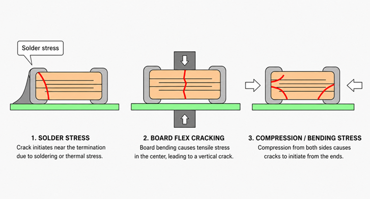
MLCC damage can appear in several forms. Some failure modes are visible under a microscope, while others require electrical testing, X-ray inspection, CT scan analysis, or cross-section analysis.
| Failure Type | Typical Cause | Possible Circuit Symptom |
|---|---|---|
| External crack | Board flex, soldering stress, mechanical impact | Intermittent capacitance change or open circuit |
| Internal crack | PCB bending, thermal cycling, mounting stress | Leakage, intermittent short, unstable operation |
| Short circuit | Dielectric breakdown or crack across internal electrodes | Power rail collapse, high current draw, damaged regulator |
| Capacitance loss | DC bias, wrong dielectric selection, aging | Higher ripple, poor decoupling, unstable power rail |
| Overheating | Ripple current, high ESR loss, poor application margin | Temperature rise, drift, long-term reliability degradation |
The most dangerous MLCC failure mode is usually a short circuit on a power rail. In low-voltage systems, a shorted MLCC can pull down the entire rail. In high-current systems, the failure may also damage upstream regulators, current-limit circuits, or PCB traces.
Mechanical Stress and MLCC Cracking
Mechanical stress is one of the most common causes of MLCC cracking. Because MLCCs are made from ceramic material, they are strong under compression but weak under bending stress. When a PCB bends, the solder joints can transfer stress into the ceramic body and create cracks inside the capacitor.
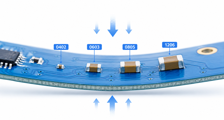
Typical sources of mechanical stress include:
- PCB bending during assembly or handling
- panel depanelization stress
- screw mounting near the capacitor
- connector insertion force
- thermal expansion mismatch
- poor solder joint geometry
- large MLCC packages placed near board edges
Large MLCC case sizes are often more sensitive to board flex because the longer ceramic body experiences more stress across the solder joints. This is why 1206 and 1210 MLCCs may require more careful placement than smaller 0402 or 0603 capacitors, especially in automotive, industrial, and power supply designs.
When changing a capacitor footprint during redesign or second-source evaluation, package size should not be treated as a simple mechanical detail. An MLCC Case Size Converter can help compare EIA and metric MLCC case sizes before changing footprints or reviewing alternate packages.
MLCC Internal Cracks and Failure Analysis
An MLCC internal crack may not be visible from the outside. The capacitor can pass a quick visual inspection while still having a defect inside the ceramic stack. This is why searches such as MLCC x ray crack, MLCC CT scan, MLCC inside, and MLCC interior crack are common in failure analysis work.
Internal cracks can create several different electrical behaviors. If the crack does not cross active electrodes, the capacitor may continue working for some time. If the crack grows or connects electrode layers, leakage current or short circuit behavior may appear later. This delayed failure is one reason MLCC cracking can be difficult to diagnose during production testing.
| Inspection Method | What It Can Reveal | Typical Use |
|---|---|---|
| Visual inspection | External cracks, chipped corners, solder defects | First-level inspection |
| X-ray inspection | Large internal cracks, solder voids, internal structure issues | Non-destructive failure analysis |
| CT scan | Three-dimensional internal crack location | Advanced failure analysis |
| Cross-section analysis | Detailed ceramic layer and electrode damage | Destructive root-cause confirmation |
| Electrical testing | Capacitance loss, leakage, short circuit, insulation resistance change | Functional diagnosis |
In real production environments, many MLCC crack problems are traced back to board-level process stress rather than capacitor quality alone. This is why placement, PCB handling, and assembly process control matter as much as component selection.
Voltage Stress and MLCC Derating
Voltage stress is another major factor in MLCC reliability. A capacitor may have a rated voltage printed in the datasheet, but high-reliability designs usually avoid operating continuously near that maximum rating.
Voltage derating means selecting a capacitor with a voltage rating higher than the actual operating voltage. This gives the dielectric more margin and reduces long-term electrical stress.
For example, using a 6.3V MLCC on a 5V rail may be acceptable in some low-cost applications, but it may not provide enough margin for harsh environments, transients, or high-reliability systems. A 10V, 16V, or higher-rated MLCC may be more appropriate depending on the application, dielectric type, package size, and available space.
An MLCC Voltage Derating Calculator can help check whether the selected voltage rating provides enough margin for the operating rail. This is especially useful for industrial, automotive, medical, and AI server power designs where reliability margin is more important than using the smallest possible component.
DC Bias and Effective Capacitance Loss
DC bias does not always physically damage an MLCC, but it can make the capacitor behave very differently from its nominal value. This is one of the most common sources of confusion when replacing or selecting high-capacitance ceramic capacitors.
Class II dielectric MLCCs such as X5R, X6S, X7R, and X7T can lose effective capacitance when DC voltage is applied. The smaller the package and the higher the capacitance density, the more important this effect can become.
For example, a capacitor marked as 22μF may provide much less effective capacitance at its real operating voltage. In a decoupling network or DC-DC converter output, this can cause higher ripple, weaker transient response, or stability margin problems.
An MLCC DC Bias Calculator can help estimate effective capacitance under real operating voltage. This is useful when comparing MLCC replacement options or checking whether a power rail still has enough usable capacitance after DC bias is considered.
MLCC Short Circuit Failure
A shorted MLCC is one of the most serious capacitor failure modes. It can pull down a power rail, trigger overcurrent protection, or cause localized heating. In some cases, the failed capacitor becomes difficult to identify because multiple capacitors are connected in parallel across the same rail.
Common causes of MLCC short circuit failure include:
- internal cracking across electrode layers
- dielectric breakdown from excessive voltage stress
- manufacturing defect or contamination
- mechanical damage during assembly
- surge or transient overstress
- operation without enough voltage derating
In repair work, a shorted MLCC on a low-voltage rail may look like a shorted IC or failed regulator at first. Thermal imaging, current injection, resistance comparison, and selective removal are often used to isolate the failed component.
Incorrect Replacement Can Create New MLCC Problems
MLCC replacement is not just matching the same nominal capacitance. A substitute capacitor should be checked for voltage rating, dielectric type, package size, DC bias behavior, temperature characteristic, and mechanical suitability.
Common replacement mistakes include:
- using the same capacitance value but a lower voltage rating
- replacing X7R with Y5V or another less stable dielectric
- using a smaller package without checking DC bias loss
- using a larger package without considering board flex stress
- ignoring capacitance tolerance and temperature behavior
- assuming all 10μF MLCCs behave the same in circuit
This is where MLCC damage prevention connects directly with component sourcing. During shortage conditions, engineers may approve alternate MLCCs from another supplier or another package family. The replacement may fit electrically on paper but fail mechanically or perform poorly under real operating conditions.
MLCC Damage in Power Supply and Decoupling Circuits
MLCCs used in power supply and decoupling circuits often operate under fast transient conditions. They may be connected close to regulators, processors, FPGAs, memory devices, RF circuits, or switching converters.
In these positions, MLCCs help reduce voltage ripple and support fast current changes. If the capacitor network loses effective capacitance because of DC bias, poor derating, or wrong package selection, the circuit may show symptoms that look like random instability.
Typical symptoms include:
- higher output ripple
- processor reset under load
- unstable regulator behavior
- sensor noise increase
- EMI problems
- unexpected heating near the capacitor bank
Not all of these symptoms mean the MLCC is physically damaged. Sometimes the design simply does not have enough effective capacitance under real voltage, temperature, and frequency conditions. That distinction matters during troubleshooting.
How PCB Layout Reduces MLCC Failure Risk
PCB layout has a major influence on MLCC reliability. A technically correct capacitor may still fail if it is placed in a mechanically weak location.
Design practices that reduce MLCC cracking risk include:
- avoid placing large MLCCs near board edges
- avoid placing MLCCs close to mounting screws or connectors
- align MLCCs to reduce stress from board bending direction
- use smaller case sizes when capacitance and voltage margin allow
- consider soft-termination MLCCs in high-stress applications
- control depanelization and assembly handling stress
- verify solder pad design and solder volume
For high-reliability products, MLCC placement should be reviewed together with mechanical design. This is especially important in automotive modules, handheld devices, industrial controllers, and boards installed in vibrating environments.
How to Prevent MLCC Damage in Design
Preventing MLCC damage usually requires both electrical and mechanical margin. A reliable design does not depend only on nominal capacitance value.
| Design Area | What to Check | Reason |
|---|---|---|
| Package size | Compare footprint, board flex risk, available space | Larger packages may be more sensitive to mechanical cracking |
| Voltage rating | Apply proper derating | Reduces dielectric stress and breakdown risk |
| DC bias | Estimate effective capacitance under operating voltage | Prevents hidden capacitance shortage |
| Dielectric type | Check X5R, X6S, X7R, X7T, C0G/NP0 behavior | Temperature and voltage behavior can vary widely |
| PCB placement | Avoid high-stress locations | Reduces cracking from board bending |
| Assembly process | Control soldering, depanelization, and handling | Reduces process-induced damage |
A practical prevention strategy is to review the MLCC from three angles: mechanical stress, electrical stress, and real in-circuit capacitance. Case size affects mechanical risk. Voltage rating affects dielectric stress. DC bias affects usable capacitance. Missing any of these checks can lead to field problems even when the schematic appears correct.
MLCC Failure Analysis Checklist
When investigating MLCC capacitor failure, the following checklist can help narrow the root cause.
- Check whether the failure is short circuit, open circuit, leakage, or capacitance loss.
- Inspect the MLCC body for external cracks, chips, or solder stress.
- Review PCB bending, mounting points, connectors, and depanelization process.
- Check whether the MLCC voltage rating has enough derating margin.
- Estimate effective capacitance under DC bias conditions.
- Compare package size and mechanical stress sensitivity.
- Use X-ray or CT scan if an internal crack is suspected.
- Review whether alternate parts have the same dielectric and reliability grade.
MLCC damage is often preventable when mechanical stress, voltage margin, and effective capacitance are reviewed before production. In modern compact electronics, MLCCs are no longer simple passive parts that can be substituted only by nominal value. They are reliability-sensitive components that require careful selection, layout review, and validation under real operating conditions.


