
 My Inquiry
 My Account


How to Check Input Margin for Stable Regulation
Article Details
Designing a reliable LDO regulator circuit starts with checking input voltage margin. In battery-powered, low-voltage, and space-limited systems, an LDO can lose regulation if the input voltage gets too close to the required output voltage. This condition is usually related to LDO dropout voltage, load current, temperature, and the minimum available supply voltage.
Dropout margin is easy to overlook because the circuit may look correct in the schematic. The regulator part number may support the required output current, and the output voltage may be properly selected. But if the available input voltage is not high enough above the output voltage, the regulator cannot maintain stable output under real operating conditions.
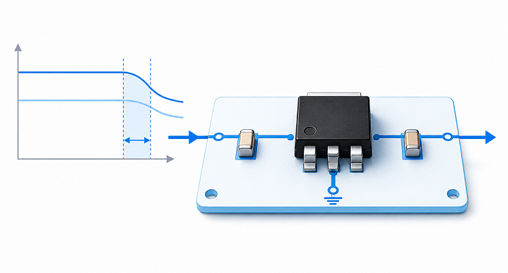
Understanding LDO Dropout Voltage
The dropout voltage of a low dropout regulator is the minimum voltage difference between input voltage and output voltage required to keep the regulator operating normally.
In simple terms:
VIN must be higher than VOUT by at least the dropout voltage.
If the input voltage falls below this level, the LDO enters dropout. The output voltage is no longer tightly regulated and begins to follow the input voltage downward.
The basic relationship is:
Minimum VIN = VOUT + Dropout Voltage
For example, if an LDO provides 3.3V output and has a dropout voltage of 300mV at the required load current, the input voltage should stay above:
3.3V + 0.3V = 3.6V
In real designs, a little extra voltage headroom is usually added to account for battery sag, cable loss, PCB trace resistance, load transients, and temperature variation.
Why Input Margin Matters
Input margin is the voltage headroom between the actual input voltage and the minimum voltage needed by the LDO.
For stable regulation, the input margin should remain positive under worst-case conditions.
| Parameter | Meaning |
|---|---|
| VIN | Actual input voltage supplied to the LDO |
| VOUT | Required regulated output voltage |
| Dropout Voltage | Minimum voltage difference needed for regulation |
| Input Margin | Extra voltage headroom above the dropout requirement |
A design with very small input margin may work during early bench testing but fail later when the battery voltage drops, the load current increases, or the system operates at high temperature.
This is common in compact embedded products where every millivolt of supply voltage is already being used tightly.
How to Calculate LDO Input Margin
The input margin can be estimated with a simple calculation:
Input Margin = VIN − VOUT − Dropout Voltage
Example:
| Item | Value |
|---|---|
| Input Voltage | 5V |
| Output Voltage | 3.3V |
| Dropout Voltage | 0.3V |
The available input margin is:
5V − 3.3V − 0.3V = 1.4V
This is usually enough margin for many 3.3V LDO designs.
Now compare that with a battery-powered system:
| Item | Value |
|---|---|
| Minimum Battery Voltage | 3.5V |
| Output Voltage | 3.3V |
| Dropout Voltage | 0.3V |
The available input margin becomes:
3.5V − 3.3V − 0.3V = −0.1V
This means the LDO cannot maintain full regulation at the minimum battery voltage. The output may sag before the battery is actually empty.
Checking Minimum VIN Before Selecting an LDO
Minimum VIN should be checked before finalizing the regulator part number. The common mistake is checking only nominal supply voltage instead of worst-case supply voltage.
For example, a system may be described as using a 5V rail, but the real voltage at the regulator input may be lower because of connector resistance, cable voltage drop, upstream regulator tolerance, or surge current during startup.
When the available input voltage is close to the output voltage, dropout margin becomes a design constraint rather than a minor datasheet value.
An LDO Dropout Voltage Calculator fits naturally into this step because it helps compare VIN, VOUT, dropout voltage, and available headroom before the regulator is selected.
This is especially useful when comparing multiple LDO regulators with different dropout specifications at different load currents.
Load Current and Dropout Voltage
LDO dropout voltage is not always a fixed number. It often increases as load current increases.
A regulator may have very low dropout at light load but much higher dropout near maximum rated current. This is why datasheet conditions matter.
| Load Current | Typical Dropout Behavior |
|---|---|
| Light load | Lower dropout voltage |
| Medium load | Moderate dropout voltage |
| Full load | Highest dropout voltage |
For production designs, dropout margin should be checked at maximum expected load current, not only at typical operating current.
This matters in systems with wireless modules, motors, displays, sensors, or processors that create short current peaks. The average current may look safe, while peak current temporarily pushes the LDO close to dropout.
Battery-Powered LDO Designs
Battery-powered systems are one of the most common places where LDO dropout voltage becomes important.
A battery does not provide a constant voltage during discharge. The voltage gradually decreases, and it may drop further under high load pulses.
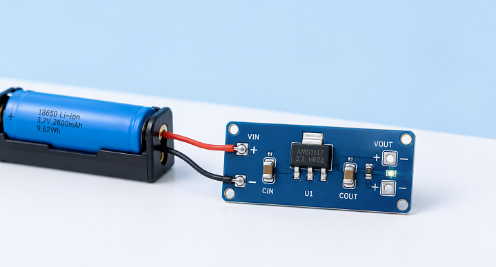
For example, a single lithium-ion cell may start above 4V and later drop close to 3.3V. If the system requires a regulated 3.3V rail, even a low dropout regulator may eventually lose regulation as the battery voltage falls.
In this kind of design, the important question is not only whether the LDO works at full battery voltage. The real question is how long the system can stay in regulation as the battery discharges.
For portable devices, dropout margin affects:
- usable battery capacity
- minimum operating voltage
- output stability near end-of-discharge
- system reset behavior
- sensor and analog circuit accuracy
Temperature and Datasheet Conditions
Dropout voltage may also change with temperature. Semiconductor behavior is not identical at room temperature and high operating temperature.
Datasheets usually specify dropout voltage under certain test conditions, such as a specific load current and junction temperature. A value measured at 25°C may not represent worst-case system behavior.
For industrial, automotive, or outdoor electronics, the minimum input voltage should be checked at higher ambient temperature and maximum load current. This avoids designing a regulator that works on the bench but becomes marginal inside a warm enclosure.
PCB Voltage Drop and Real Input Voltage
The voltage at the LDO input pin may not be exactly the same as the voltage measured at the power connector.
Voltage can be lost through:
- long PCB traces
- small connectors
- reverse protection diodes
- ferrite beads
- input filters
- cable resistance
For low-voltage rails, these losses can become significant. A 100mV drop may not matter in a 24V industrial power rail, but it can matter a lot in a 3.3V battery system with limited dropout margin.
For accurate input margin analysis, the VIN value should be taken at the LDO input pin under load, not only at the system power entry point.
Dropout Voltage and Output Stability
When an LDO approaches dropout, output regulation becomes weaker. The output may still appear close to the target voltage, but line regulation and load transient performance can degrade.
This is especially important for:
- ADC reference supplies
- sensor power rails
- RF circuits
- analog front-end circuits
- low-noise amplifier rails
Analog circuits may be more sensitive to small voltage changes than digital logic. A digital circuit may continue running, while a sensor or analog signal chain may lose accuracy.
Common Dropout Voltage Mistakes
Most dropout-related problems come from optimistic assumptions during design.
| Mistake | Why It Causes Problems |
|---|---|
| Using nominal VIN only | Ignores low supply conditions |
| Ignoring load current | Dropout voltage increases at higher current |
| Ignoring battery sag | Portable devices may lose regulation early |
| Ignoring PCB voltage drop | VIN at the LDO pin may be lower than expected |
| Using typical datasheet values only | Worst-case behavior may be different |
These mistakes are often difficult to see from the schematic alone. They usually appear during prototype testing, temperature testing, or field operation.
When a Low Dropout Regulator Is Still Not Enough
A low dropout regulator helps reduce the required input-output voltage difference, but it does not eliminate the need for margin.
If the input source frequently falls below the required minimum VIN, the design may need a different power architecture.
Possible solutions include:
- choosing an LDO with lower dropout at the required load current
- using a buck-boost converter before the LDO
- lowering the regulated output voltage if the system allows it
- reducing load current during low-battery operation
- adding system-level undervoltage detection
In some battery-powered products, an LDO is used only for low-noise post-regulation after a switching converter. This keeps the analog rail clean while avoiding excessive dropout limitations across the entire battery discharge range.
Practical LDO Input Margin Checklist
Stable LDO output regulation depends on more than the selected output voltage. The input supply must remain high enough across real operating conditions.
- Check minimum VIN at the LDO input pin, not only at the power connector.
- Use worst-case dropout voltage at maximum load current.
- Include battery sag and cable voltage drop.
- Consider temperature effects from the datasheet.
- Verify margin during peak load conditions.
- Use a lower-dropout device if the available input headroom is small.
- Consider switching pre-regulation if the margin is not reliable.
Good LDO dropout design is mostly about margin. A regulator that works at nominal conditions may still fail at low input voltage, high current, high temperature, or battery end-of-discharge. Checking dropout voltage early helps avoid unstable output rails and late-stage PCB redesign.


