What Is an Actuator? Types, Working Principles, Applications and Troubleshooting
Article Details
An actuator is a device that converts a control signal and an energy source into mechanical motion. The output may be linear movement, rotary movement, valve opening, door locking, throttle movement, airflow control, lifting, pushing, clamping, or positioning. Actuators are used in industrial automation, automotive systems, robotics, HVAC equipment, medical devices, valve control, consumer appliances, and electronic control systems.
The word actuator covers many device types. An electric actuator may use a DC motor, stepper motor, BLDC motor, solenoid, or voice coil. A pneumatic actuator uses compressed air. A hydraulic actuator uses pressurized fluid. A linear actuator creates straight-line motion, while a rotary actuator creates angular motion. In many modern systems, the actuator is not just a mechanical part; it also depends on driver circuits, feedback sensors, wiring, protection components, and controller logic.
This guide explains what an actuator is, how actuators work, the main actuator types, electric and linear actuator design, pneumatic and hydraulic actuation, automotive actuator examples, actuator control electronics, bench test methods, common failure cases, troubleshooting steps, and actuator selection points.
What Is an Actuator?
An actuator is a machine component or electromechanical device that turns a command into physical motion. The controller sends a signal, the driver or valve provides controlled energy, and the actuator moves a load.
| Item | Simple Explanation |
|---|---|
| Main function | Converts a control signal into mechanical motion |
| Common energy sources | Electrical power, compressed air, hydraulic fluid pressure, magnetic force, or piezoelectric effect |
| Common motion types | Linear motion, rotary motion, push-pull movement, valve rotation, short-stroke actuation |
| Typical control signals | On/off command, PWM, analog voltage, current loop, digital command, relay control, or closed-loop feedback control |
| Common applications | Valves, locks, HVAC doors, robots, industrial machines, motorized mechanisms, test systems, and vehicle systems |
Actuator Definition
An actuator is a device that receives a command and produces a mechanical output. The command may come from a microcontroller, PLC, ECU, relay circuit, motor controller, pneumatic valve, hydraulic valve, or manual control system. The actuator uses energy to move a mechanical load.
In a complete actuator system, the actuator is often only one part of the chain. A practical system may include a controller, motor driver, power stage, gearbox, screw mechanism, spring return, position sensor, limit switch, current sensor, connector, cable harness, and mechanical linkage.
| System Element | Role in an Actuator System |
|---|---|
| Controller | Decides when and how the actuator should move |
| Driver circuit | Converts low-power command signals into actuator drive current or voltage |
| Energy source | Provides electrical, pneumatic, or hydraulic power |
| Actuator mechanism | Creates linear, rotary, or short-stroke movement |
| Load | The valve, lock, lever, door, linkage, screw, or mechanical structure being moved |
| Feedback element | Reports position, speed, current, force, pressure, or limit state back to the controller |
How Does an Actuator Work?
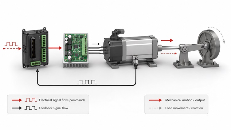
Most actuator systems follow a similar control path. A controller sends a command. A driver, valve, or power stage applies energy. The actuator converts that energy into motion. The mechanical output moves the load. If the system is closed-loop, a feedback sensor reports position, force, pressure, current, or limit status.
In an electric actuator, the driver circuit may control motor direction and speed through an H-bridge, MOSFET stage, motor driver IC, relay, or inverter. In a pneumatic actuator, a solenoid valve controls air pressure into the cylinder or rotary chamber. In a hydraulic actuator, a hydraulic valve controls pressurized fluid. In a solenoid actuator, an electromagnetic coil pulls or pushes a plunger over a short stroke.
| Step | What Happens | Example |
|---|---|---|
| 1. Command | The controller sends an actuation request | ECU requests a blend door to move |
| 2. Drive | The driver provides controlled power or pressure | H-bridge drives a small DC motor |
| 3. Motion | The actuator converts energy into movement | Motor and gears rotate an output shaft |
| 4. Load movement | The actuator moves the mechanical target | A door, valve, rod, latch, or lever changes position |
| 5. Feedback | A sensor or limit switch confirms state | Position sensor reports the final angle |
| 6. Stop or adjust | The controller stops or corrects the motion | Driver disables current when the target position is reached |
The following video gives a general visual explanation of what actuators do and how they convert input energy into motion.
Main Types of Actuators
Actuators are usually classified by energy source, output motion, and mechanical structure. The same application may be possible with more than one actuator type, but each option has different trade-offs in force, speed, control accuracy, noise, cost, efficiency, maintenance, and environment.

| Actuator Type | Energy Source | Motion Type | Common Use |
|---|---|---|---|
| Electric actuator | Electrical power | Linear or rotary | Automation, valves, robotics, automotive systems, adjustable mechanisms |
| Linear actuator | Electric, pneumatic, or hydraulic | Straight-line motion | Lifting, pushing, pulling, positioning, height adjustment |
| Rotary actuator | Electric, pneumatic, or hydraulic | Angular or rotational motion | Valve control, robotics, indexing, dampers, rotary positioning |
| Pneumatic actuator | Compressed air | Linear or rotary | Factory automation, valve operation, clamps, packaging machinery |
| Hydraulic actuator | Pressurized fluid | Linear or rotary | Heavy machinery, high-force systems, construction equipment |
| Solenoid actuator | Electromagnetic coil | Short push-pull stroke | Locks, relays, valves, latches, small switching mechanisms |
| Piezo actuator | Piezoelectric effect | Very small precise displacement | Optics, precision positioning, micro-motion systems |
Electric Actuator
An electric actuator uses electrical energy to create motion. It may use a DC motor, stepper motor, BLDC motor, AC motor, solenoid, or voice coil. The motor output may be connected to a gearbox, screw, belt, rack, linkage, or valve shaft to create the required movement.
Electric actuators are common when the system needs controlled motion without compressed air or hydraulic power. They are used in industrial machines, automotive systems, medical equipment, robotics, smart furniture, valve automation, HVAC systems, and electromechanical control panels.
| Electric Actuator Block | Function |
|---|---|
| Motor | Converts electrical energy into rotation or force |
| Gearbox | Increases torque or reduces speed |
| Lead screw or linkage | Converts rotary motion into linear motion when needed |
| Driver circuit | Controls direction, current, speed, braking, and protection |
| Limit switch | Detects end-of-travel position |
| Feedback sensor | Reports position, angle, current, speed, or load condition |
Linear Actuator
A linear actuator produces straight-line motion. It can push, pull, lift, lower, extend, retract, or position a mechanical load. Linear actuators may be electric, pneumatic, or hydraulic, depending on the force, speed, accuracy, and environment required.
Electric linear actuators often use a motor and screw mechanism. Pneumatic linear actuators use air pressure and a piston. Hydraulic linear actuators use fluid pressure for high-force movement. The correct design depends on stroke length, load capacity, speed, duty cycle, voltage, feedback, mounting style, and environmental protection.
| Linear Actuator Parameter | Why It Matters |
|---|---|
| Stroke length | Defines the maximum travel distance |
| Load capacity | Defines how much force the actuator can move or hold |
| Speed | Determines how quickly the actuator reaches position |
| Duty cycle | Limits how often the actuator can operate without overheating or wear |
| Feedback type | Allows closed-loop position or speed control |
| Mounting style | Determines how force is transferred to the mechanical structure |
| Environmental rating | Important for dust, water, temperature, vibration, or outdoor exposure |
Pneumatic Actuator
A pneumatic actuator uses compressed air to create motion. It is common in factory automation, valve control, packaging equipment, clamps, pick-and-place systems, and repetitive industrial motion. Pneumatic systems can be fast, rugged, and simple, especially where compressed air is already available.
A typical pneumatic cylinder contains a piston, rod, seals, ports, and body. Air pressure applied to one side of the piston creates force and movement. In a double-acting cylinder, air pressure controls both extension and retraction. In a spring-return actuator, a spring returns the actuator when air pressure is released.
| Pneumatic Parameter | Design Impact |
|---|---|
| Air pressure | Determines available force together with piston area |
| Bore size | Larger bore increases force but may require more air volume |
| Stroke | Defines travel distance |
| Flow rate | Affects speed and response time |
| Valve type | Controls extension, retraction, exhaust, and fail-safe behavior |
| Leakage | Can reduce force, slow movement, and increase air consumption |
Hydraulic and Solenoid Actuators
Hydraulic actuators use pressurized fluid to generate high force. They are widely used in heavy machinery, construction equipment, presses, steering systems, lifting systems, and other high-load applications. Their advantages include high force density and strong holding capability, but they require hydraulic pumps, valves, fluid handling, seals, and maintenance.
Solenoid actuators use an electromagnetic coil to pull or push a plunger. They are common in door locks, valves, latches, relays, safety mechanisms, and short-stroke switching systems. Solenoids are usually simple and fast, but they are not ideal for long travel or high-precision positioning unless combined with additional mechanisms or sensors.
| Actuator Type | Strength | Limitation |
|---|---|---|
| Hydraulic actuator | Very high force and strong holding capability | Requires fluid system, seals, pumps, valves, and maintenance |
| Solenoid actuator | Simple, fast, compact short-stroke movement | Limited stroke, heat rise, and force curve must be checked |
| Piezo actuator | Very fine movement and fast response | Small displacement and specialized drive requirements |
Automotive Actuators: Door Lock, Blend Door and Throttle Actuators
Automotive systems use many actuators. Search interest is especially strong for door lock actuators and blend door actuators because these parts commonly appear in repair and replacement scenarios. However, the same actuator principles also apply to throttle control, turbo control, variable valve timing, seat adjustment, mirror adjustment, headlamp leveling, and active grille shutters.
| Automotive Actuator | Function | Common Symptom When Faulty |
|---|---|---|
| Door lock actuator | Locks or unlocks the vehicle door latch mechanism | No lock movement, weak movement, clicking, intermittent operation |
| Blend door actuator | Moves HVAC air doors to control hot/cold air mix or airflow direction | Clicking behind dashboard, stuck temperature, airflow direction fault |
| Throttle actuator | Controls electronic throttle plate movement | Reduced power, unstable idle, fault code, limp mode |
| Turbo actuator | Controls wastegate or variable geometry turbo mechanism | Low boost, overboost, slow response, diagnostic trouble code |
| Seat actuator | Moves seat position, tilt, height, or lumbar adjustment | Motor noise, no movement, uneven travel, high current |
Automotive actuator diagnosis should not start by replacing the actuator immediately. Wiring, connectors, power supply, ground path, command signal, mechanical binding, and feedback signal should be checked first. In many field failures, the actuator is only one part of the system fault.
Actuator Control Electronics
Electric actuators need control electronics to convert logic-level commands into usable actuator power. A microcontroller pin cannot directly drive a motor, solenoid, or high-current load. The circuit usually needs a motor driver, MOSFET, H-bridge, relay driver, gate driver, current sense resistor, flyback protection, TVS diode, or other protection components.
Texas Instruments describes its motor driver portfolio as covering integrated motor drivers, smart gate drivers, and functional-safety devices for improving motor performance and simplifying motor-drive design. (Texas Instruments, Motor Drivers)
| Electronic Component | Role in Actuator Control |
|---|---|
| Motor driver IC | Drives DC, stepper, or BLDC motors with direction, speed, and protection control |
| H-bridge | Allows bidirectional control of a DC motor or linear actuator motor |
| MOSFET | Switches actuator current in low-side, high-side, or bridge configurations |
| Gate driver | Controls external MOSFETs for higher current or voltage systems |
| Current sense resistor | Measures actuator current for load detection, stall detection, and protection |
| TVS diode | Protects electronics from transients on actuator wiring |
| Flyback diode or clamp | Controls inductive voltage spikes from coils, solenoids, and motors |
| Position sensor | Reports actuator position through potentiometer, Hall sensor, encoder, or other feedback |
| MCU or ECU | Processes command logic, feedback, diagnostics, and control algorithms |
Bench Test Method for Electric Actuators
Useful actuator content should include test methods, but it should not invent laboratory data. The correct approach is to explain what engineers or technicians can measure, how to measure it, and what the result may indicate. Actual limits should come from the actuator datasheet, service manual, golden sample, or system specification.
| Test Item | Method | What It Indicates |
|---|---|---|
| Coil or motor resistance | Measure resistance with a multimeter when disconnected from the driver | Open circuit, short circuit, winding damage, or wrong replacement part |
| No-load current | Power the actuator without load using a current-limited supply | Motor health, internal friction, gear drag, or abnormal current draw |
| Load current | Measure current under normal mechanical load | Overload, binding, weak motor, worn gear, or undersized driver |
| Stroke time | Measure travel time from one end position to the other | Slow actuator, low supply voltage, friction, or mechanical obstruction |
| Limit switch state | Check continuity or logic state at each end of travel | End-position detection failure or switch wiring fault |
| Feedback voltage | Measure position sensor voltage while moving the actuator | Open wiper, noisy sensor, broken feedback track, or wrong calibration |
| PWM or drive waveform | Use an oscilloscope at the motor driver output or control input | Driver fault, missing command signal, PWM issue, or protection shutdown |
| Connector voltage drop | Measure voltage at the actuator while it operates under load | Weak wiring, corroded connector, poor ground, or supply limitation |
Common Actuator Failure Cases and Troubleshooting
Actuator faults can be electrical, mechanical, pneumatic, hydraulic, or control-related. A useful troubleshooting process separates these categories instead of assuming the actuator itself has failed.
| Failure Case | Symptom | Likely Cause | Useful Test |
|---|---|---|---|
| Door lock actuator clicks but does not move | Clicking sound, weak or no lock movement | Weak motor, broken gear, low voltage, latch binding | Measure voltage and current during actuation; check latch movement manually |
| Blend door actuator keeps clicking | Repeated clicking behind dashboard | Stripped gear, lost position feedback, calibration error | Remove actuator and check output shaft movement and feedback signal |
| Linear actuator moves slowly | Slow stroke, high current, uneven travel | Overload, worn screw, low supply voltage, mechanical friction | Measure stroke time, current, and voltage at actuator terminals |
| Pneumatic actuator moves weakly | Delayed or incomplete motion | Low air pressure, leakage, sticky valve, undersized flow path | Check pressure, leakage, valve function, and air flow |
| Electric valve actuator hunts around target | Small repeated corrections near final position | Noisy feedback, loose linkage, control loop instability | Check feedback signal stability and mechanical backlash |
| Solenoid overheats | Hot coil, weak pull-in, burning smell | Wrong duty cycle, overvoltage, stuck plunger, incorrect coil rating | Check voltage, coil resistance, duty cycle, and plunger movement |
| Actuator works on bench but not in system | Normal bench movement, failure after installation | Mechanical load too high, connector issue, control signal missing, binding | Test voltage at installed actuator under load and inspect linkage alignment |
Actuator Troubleshooting Steps
A structured troubleshooting sequence reduces unnecessary replacement. The actuator should be checked together with the power path, driver circuit, command signal, feedback sensor, and mechanical load.
- Identify the actuator type: electric, pneumatic, hydraulic, solenoid, linear, rotary, or valve actuator.
- Confirm the rated voltage, current, pressure, force, stroke, feedback type, and duty cycle from the datasheet or service information.
- Check connectors, pins, seals, wiring harness, ground path, air lines, hydraulic lines, and mechanical linkage.
- Verify the command signal from the controller, ECU, PLC, relay, or driver circuit.
- Measure supply voltage at the actuator while the actuator is commanded to move.
- Measure actuator current or pressure during operation and compare with a known-good unit or specification.
- Disconnect the mechanical load when safe and test whether the actuator moves freely without load.
- Check limit switches, Hall sensors, potentiometer feedback, encoders, or other position sensors.
- Inspect for mechanical binding, stripped gears, bent rods, contamination, leakage, worn seals, or damaged linkages.
- Replace the actuator only after electrical, mechanical, and control-side faults have been reasonably isolated.
Replacement and Production-Change Checks
Replacement actuators should not be selected only by appearance. A part that looks similar may have different stroke length, gear ratio, connector pinout, motor winding, feedback sensor range, duty cycle, mounting angle, or control protocol.
When an original manufacturer changes a production line, material, motor, gearset, connector, driver IC, feedback element, or calibration process, the replacement part may still fit mechanically but behave differently in the system. For verified changes, engineers should check official datasheets, product change notices, service bulletins, approved vendor lists, and revision markings rather than relying on generic cross-reference information.
| Replacement Check | Why It Matters |
|---|---|
| Part number and revision | Confirms whether the actuator belongs to the correct design version |
| Connector and pinout | Prevents wiring mismatch and driver damage |
| Stroke or rotation angle | Ensures the actuator reaches the required mechanical range |
| Motor or coil resistance | Indicates whether the replacement load matches the driver circuit |
| Feedback signal range | Prevents calibration errors and position-control faults |
| Mounting geometry | Prevents preload, binding, or incorrect linkage movement |
| Duty cycle and temperature rating | Prevents overheating and premature failure |
How to Choose an Actuator
Actuator selection should start with the mechanical requirement, then move to control and electrical requirements. The actuator must move the load, fit the space, survive the environment, and match the driver or control system.
| Selection Point | What to Check |
|---|---|
| Motion type | Linear, rotary, short stroke, continuous rotation, or valve actuation |
| Force or torque | Required output under worst-case load and friction |
| Stroke or angle | Required travel distance or rotation range |
| Speed | Required movement time and response behavior |
| Duty cycle | How often the actuator operates and how long it remains energized |
| Power source | Voltage, current, air pressure, hydraulic pressure, or available system power |
| Feedback | Limit switch, potentiometer, Hall sensor, encoder, pressure sensor, or no feedback |
| Control method | On/off, PWM, analog command, digital command, position loop, or force loop |
| Environment | Temperature, vibration, water, dust, chemicals, EMI, and mechanical shock |
| Driver compatibility | Current rating, voltage rating, protection features, diagnostics, and thermal limits |
| Lifecycle and sourcing | Availability, revision control, replacement strategy, and long-term supply |
Actuator and Related Electronic Components
Actuator systems often depend on electronic components beyond the actuator itself. The control electronics may determine response time, protection behavior, noise immunity, diagnostics, and service life.
Related components and ICs may include motor driver ICs, MOSFETs, gate drivers, Hall sensors, TVS diodes, microcontrollers, op amps, and connectors. These links can be updated later to point to specific Aetrix product pages.
Frequently Asked Questions
What is an actuator?
An actuator is a device that converts a command signal and an energy source into mechanical motion. It may create linear movement, rotary movement, valve movement, locking movement, or positioning motion.
What is an actuator definition in simple words?
In simple terms, an actuator is the part of a system that makes something move after receiving a control command.
What are the main types of actuators?
Common actuator types include electric actuators, linear actuators, rotary actuators, pneumatic actuators, hydraulic actuators, solenoid actuators, and piezo actuators.
What is an electric actuator?
An electric actuator uses electrical power to create controlled motion. It may use a motor, gearbox, screw, solenoid, driver circuit, and feedback sensor.
What is a linear actuator?
A linear actuator creates straight-line motion. It can push, pull, lift, lower, extend, retract, or position a load.
What is a pneumatic actuator?
A pneumatic actuator uses compressed air to produce motion. It is common in factory automation, valve control, clamps, and repetitive industrial movement.
What does a door lock actuator do?
A door lock actuator moves the latch mechanism to lock or unlock a vehicle door. It is usually controlled by a switch, body control module, or keyless entry system.
What does a blend door actuator do?
A blend door actuator moves an HVAC air door to control air temperature or airflow direction inside a vehicle.
How do you test an actuator?
Common actuator tests include checking supply voltage, command signal, motor or coil resistance, operating current, stroke time, feedback signal, limit switch state, and mechanical binding.
Can an actuator fail because of wiring instead of the actuator itself?
Yes. Connector corrosion, voltage drop, weak ground, broken wires, missing command signal, or driver circuit failure can make a good actuator appear faulty.
An actuator is the motion-producing part of a controlled mechanical system. It may be electric, pneumatic, hydraulic, linear, rotary, solenoid-based, or piezo-based. The correct actuator depends on motion type, force, speed, stroke, duty cycle, environment, control method, feedback, and driver compatibility.
For reliable design or repair, actuator diagnosis should include both electrical and mechanical checks. Useful measurements include voltage under load, operating current, resistance, stroke time, feedback signal, limit switch state, and mechanical binding. Replacing an actuator without checking the driver, connector, power path, load, and feedback circuit can lead to repeated faults.