What Is a Potentiometer? Wiring, Types, Symbols, Uses and Selection Guide
Article Details
A potentiometer is a three-terminal variable resistor used to adjust voltage, signal level, resistance ratio, or user control input in an electronic circuit. It is common in volume controls, brightness controls, sensor calibration, analog input knobs, test equipment, power supply adjustment, and embedded systems.
The term potentiometer can refer to several physical forms, including rotary potentiometers, slide potentiometers, trimmer potentiometers, multi-turn potentiometers, ceramic potentiometers, hybrid potentiometers, mini potentiometers, and digital potentiometer ICs. The basic electrical idea is the same: a movable contact changes the relationship between resistance and output voltage.
This guide explains what a potentiometer is, how it works, how potentiometer wiring is done, what the potentiometer symbol means, how it differs from a variable resistor, common types of potentiometers, what a 10k potentiometer is used for, how digital potentiometers work, and how to choose the right part for an electronic circuit.
What Is a Potentiometer?
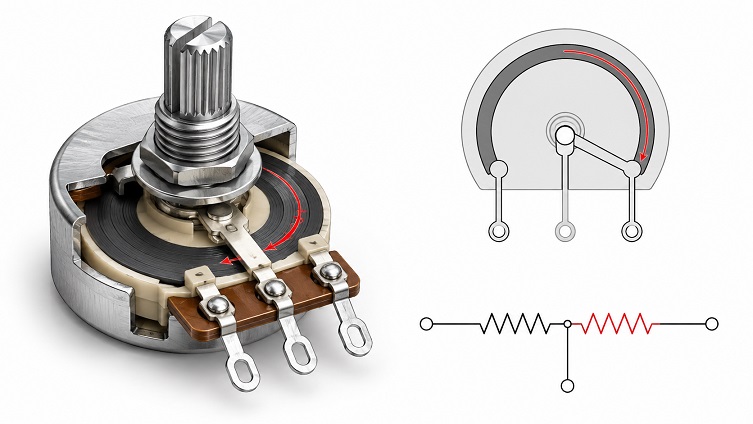
A potentiometer is a three-terminal adjustable resistor. The two outer terminals connect to the ends of a resistive element, and the middle terminal connects to a movable contact called the wiper. As the shaft, slider, or screw is moved, the wiper changes position along the resistive element.
| Item | Simple Explanation |
|---|---|
| Component type | Adjustable resistor with a movable wiper |
| Typical terminals | Three terminals: end terminal, wiper, end terminal |
| Main function | Adjusts voltage ratio or resistance in a circuit |
| Common values | 1k, 5k, 10k, 50k, 100k and other resistance values |
| Common applications | Volume control, ADC input, calibration, brightness adjustment, position sensing, and user controls |
How Does a Potentiometer Work?
A potentiometer contains a resistive track and a movable wiper. The resistive track has a fixed total resistance between the two outer terminals. The wiper touches a point along the track, dividing the total resistance into two parts.
When the wiper moves closer to one end, the resistance between the wiper and that end becomes smaller. At the same time, the resistance between the wiper and the other end becomes larger. This changing ratio is what allows a potentiometer to produce an adjustable output voltage.
If one end terminal is connected to VCC and the other end terminal is connected to ground, the wiper voltage changes between ground and VCC as the knob or slider is moved. This is why potentiometers are often used as analog control inputs for microcontrollers and ADC circuits.
Potentiometer Pinout and Wiring
Most basic potentiometers have three terminals. The two outer terminals connect to the ends of the resistive element. The middle terminal is normally the wiper. The exact physical order depends on the package, mounting style, and manufacturer, so the datasheet should be checked before PCB layout or wiring.
| Terminal | Common Role | Typical Connection in Voltage Divider Use |
|---|---|---|
| Pin 1 | One end of the resistive track | Ground or low reference |
| Pin 2 | Wiper / adjustable output | ADC input, signal input, or adjustable voltage node |
| Pin 3 | Other end of the resistive track | VCC or high reference |
Three-Terminal Potentiometer Wiring
In three-terminal wiring, the potentiometer works as a voltage divider. One outer terminal is connected to the high reference, the other outer terminal is connected to the low reference, and the wiper provides the adjustable output.
This wiring method is common for microcontroller ADC inputs, analog control knobs, audio level controls, sensor calibration, reference adjustment, and user interface controls.
Two-Terminal Potentiometer Wiring
A potentiometer can also be wired using only the wiper and one outer terminal. In this case, it behaves like a variable resistor. The resistance changes as the wiper moves.
This two-terminal use is often called rheostat mode. It should be used carefully because the current and power rating of the potentiometer become important. Many small potentiometers are intended for signal-level adjustment, not direct control of high-current loads.
Potentiometer Wiring for a Microcontroller ADC
A common embedded circuit connects one outer terminal to 3.3V or 5V, the other outer terminal to ground, and the wiper to an ADC input. As the knob turns, the ADC reads a changing voltage.
For stable ADC readings, designers may add a small capacitor from the wiper to ground, sample the ADC multiple times, or apply digital filtering in firmware. The potentiometer value should also be selected so that it does not create excessive current draw or excessive ADC source impedance.

Potentiometer Symbol
The potentiometer symbol in a schematic is usually drawn as a resistor with a movable arrow or wiper connected to the resistive element. The symbol shows that the component has an adjustable contact point.
A three-terminal potentiometer symbol represents a voltage divider. A two-terminal adjustable resistor symbol usually represents a variable resistor or rheostat. Different schematic standards may draw the symbol slightly differently, but the functional meaning is the same.
| Schematic Symbol | Meaning | Typical Use |
|---|---|---|
| Resistor with wiper arrow | Potentiometer | Voltage divider, adjustable signal level, analog input |
| Resistor with two used terminals | Variable resistor / rheostat | Adjustable resistance path |
| Trimmer symbol | Small adjustable potentiometer | Calibration and factory adjustment |
Potentiometer vs Variable Resistor
A potentiometer and a variable resistor are closely related, but the terms are not always used in the same way. A potentiometer normally means a three-terminal device used as a voltage divider. A variable resistor or rheostat normally means a two-terminal adjustable resistance.
| Item | Potentiometer | Variable Resistor / Rheostat |
|---|---|---|
| Terminals used | Three | Two |
| Main function | Adjustable voltage divider | Adjustable resistance |
| Output | Wiper voltage or signal level | Resistance value between two terminals |
| Common use | ADC input, volume control, reference adjustment | Current adjustment, bias adjustment, resistance tuning |
| Main design concern | Input impedance, noise, taper, signal range | Power rating, current rating, resistance range |
Types of Potentiometers
Potentiometers are available in many mechanical and electrical forms. The right type depends on how the user adjusts it, how often it is adjusted, how accurate it must be, and whether it is used as a front-panel control, internal calibration part, sensor, or IC-controlled adjustment device.
| Type | Description | Common Use |
|---|---|---|
| Rotary potentiometer | Adjusted by turning a shaft or knob | Volume controls, user controls, power supply adjustment |
| Slide potentiometer | Adjusted by moving a slider along a straight path | Audio mixers, lighting controls, user interface panels |
| Linear potentiometer | Output changes linearly with mechanical position or slider movement | Position sensing, control input, measurement systems |
| Trimmer potentiometer | Small adjustable part intended for calibration | Factory adjustment, bias setting, reference trimming |
| Multi-turn potentiometer | Requires multiple turns for full adjustment range | Precision setting and fine adjustment |
| Digital potentiometer | IC-controlled adjustable resistor network | Digital calibration, gain control, offset adjustment |
| Ceramic potentiometer | Uses ceramic or cermet materials for stable trimming behavior | Industrial calibration and trimming applications |
| Hybrid potentiometer | Combines material or construction features for specific performance needs | Applications requiring stability, durability, or special mechanical behavior |
| Mini potentiometer | Small package for compact designs | Consumer electronics, small modules, compact control boards |
| Dual potentiometer | Two potentiometers controlled by one shaft | Stereo audio volume, paired analog channels |
Linear vs Logarithmic Potentiometer
Potentiometer taper describes how the resistance ratio changes as the shaft or slider moves. The two most common tapers are linear taper and logarithmic taper. Choosing the wrong taper can make a control feel unnatural even if the resistance value is correct.
| Taper Type | Behavior | Common Use |
|---|---|---|
| Linear taper | Resistance ratio changes approximately in proportion to position | ADC input, measurement, general control, calibration |
| Logarithmic taper / audio taper | Resistance ratio changes in a curve that better matches human hearing | Audio volume controls |
A linear potentiometer is usually preferred for sensor inputs and microcontroller ADC controls because the electrical output is easier to map to a physical position or control value. A logarithmic potentiometer is usually preferred for volume control because human loudness perception is not linear.
What Is a 10k Potentiometer?
A 10k potentiometer has a total resistance of 10,000 ohms between the two outer terminals. It is one of the most common values used in Arduino projects, microcontroller ADC circuits, control panels, adjustment knobs, and general signal-level circuits.
A 10k value is often a practical compromise. It usually does not draw excessive current from a 3.3V or 5V supply, and it is low enough to provide a reasonably strong signal for many ADC inputs. However, the correct value still depends on the circuit.
| Potentiometer Value | Typical Effect | Design Note |
|---|---|---|
| Low resistance, such as 1k | Lower noise and stronger drive, but higher current draw | Useful when source impedance must be low |
| Medium resistance, such as 10k | Balanced current draw and signal drive | Common for MCU ADC inputs and user controls |
| High resistance, such as 100k | Lower current draw, but higher source impedance and more noise sensitivity | May require filtering or ADC input design review |
Potentiometer Applications
Potentiometers are used wherever a circuit needs adjustable analog control, calibration, or position-related information. Some applications use the potentiometer as a user interface device, while others use it as an internal adjustment element.
| Application | How the Potentiometer Is Used |
|---|---|
| Volume control | Adjusts signal level in audio circuits |
| Brightness adjustment | Provides an analog control voltage for LED dimming or display control |
| Motor speed control input | Provides a control signal to a motor driver or controller |
| Position sensing | Converts shaft, lever, or slider position into an analog voltage |
| Sensor calibration | Adjusts offset, gain, threshold, or reference level |
| Power supply adjustment | Sets output voltage or current limit in adjustable regulator circuits |
| Analog control input | Feeds an ADC input on an MCU, PLC, or control IC |
| Test equipment | Provides adjustable settings for signal level, bias, or trigger threshold |
Digital Potentiometer
A digital potentiometer is an IC that behaves like an electronically controlled adjustable resistor network. Instead of a mechanical wiper moved by a knob or slider, the wiper position is controlled through a digital interface.
Common digital potentiometer interfaces include SPI, I2C, and up/down control pins. Digital potentiometers are useful when a system needs automatic calibration, software-controlled gain, adjustable bias, filter tuning, reference trimming, or remote control.
| Digital Potentiometer Feature | Why It Matters |
|---|---|
| Resistance value | Defines the end-to-end resistance of the resistor network |
| Resolution | Defines how many steps are available between the minimum and maximum setting |
| Wiper resistance | Creates series resistance that may affect precision circuits |
| Terminal voltage range | Limits the signal voltage that can be applied to the potentiometer terminals |
| Interface | Determines how the MCU or controller changes the setting |
| Volatile or nonvolatile memory | Determines whether the setting is remembered after power is removed |
Digital potentiometers are not always drop-in replacements for mechanical potentiometers. Designers must check signal voltage range, wiper resistance, current limits, resolution, temperature behavior, and whether the part supports the required power-up setting.
How to Choose a Potentiometer
Potentiometer selection should start with the circuit function. A front-panel volume knob, an internal calibration trimmer, a position sensor, and a digital gain adjustment circuit may all use potentiometer concepts, but they require different parts.
| Selection Point | What to Check |
|---|---|
| Resistance value | Match the circuit input impedance, current draw, and noise requirement |
| Taper | Use linear taper for control/measurement and logarithmic taper for many audio volume controls |
| Power rating | Confirm the potentiometer can safely dissipate the expected power |
| Tolerance | Check whether the total resistance tolerance is acceptable |
| Number of turns | Use multi-turn parts when fine adjustment is required |
| Mechanical style | Choose rotary, slide, trimmer, shaft, knob, or panel-mount style as needed |
| Mounting type | Through-hole, SMD, panel mount, board mount, or wire connection |
| Rotational life | Important for controls that are adjusted frequently |
| Sealing | Useful in dusty, humid, or industrial environments |
| Temperature coefficient | Important for precision and calibration circuits |
| Analog or digital control | Use mechanical parts for manual adjustment and digital potentiometers for MCU-controlled settings |
| Availability | Check package, resistance value, taper, lifecycle, and sourcing options |
Bourns provides a technical library for trimming potentiometers, including product catalogs, information sheets, application notes, and a potentiometer handbook. These resources are useful when checking construction type, adjustment behavior, package style, and trimming potentiometer selection. (Bourns, Trimming Potentiometers Technical Library)
Common Potentiometer Mistakes
Potentiometers are simple parts, but circuit errors are common. Many failures happen because a potentiometer is used as a power device, connected with the wrong taper, wired incorrectly, or selected without checking electrical and mechanical limits.
- Using a small signal potentiometer to directly control a high-current load.
- Ignoring the potentiometer power rating in rheostat mode.
- Choosing linear taper when an audio taper is needed for volume control.
- Choosing logarithmic taper when a linear ADC control is needed.
- Leaving the wiper node too noisy for an ADC input.
- Using a very high resistance value without considering input leakage and noise.
- Using a very low resistance value and wasting power from the supply.
- Forgetting to filter or average ADC readings in firmware.
- Assuming every potentiometer has the same pin order.
- Using a digital potentiometer outside its terminal voltage range.
- Ignoring mechanical life in frequently adjusted user controls.
- Using a potentiometer as a precision reference when a voltage reference would be more appropriate.
Potentiometer Quick Reference
| Question | Practical Answer |
|---|---|
| How many terminals does a potentiometer have? | Most basic potentiometers have three terminals: two ends and one wiper. |
| What does the wiper do? | The wiper moves along the resistive element and provides the adjustable output point. |
| Can a potentiometer be used as a voltage divider? | Yes. This is one of the most common uses of a three-terminal potentiometer. |
| Can a potentiometer be used as a variable resistor? | Yes, by using the wiper and one end terminal, but current and power ratings must be checked. |
| Is 10k a common potentiometer value? | Yes. A 10k potentiometer is common for Arduino, MCU ADC, and signal-level control circuits. |
| Can a potentiometer control motor speed? | Usually it provides a control signal to a motor controller; it should not directly carry motor current unless rated for it. |
Potentiometer and Related Electronic Components
In many circuits, a potentiometer is used together with other components rather than alone. It may feed an ADC input, set an amplifier gain, adjust a regulator feedback node, tune a comparator threshold, or provide a control voltage to a microcontroller.
Related components and ICs may include precision resistors, digital potentiometer ICs, ADC devices, operational amplifiers, voltage references, microcontrollers, and power management ICs.
Video: Potentiometer Wiring with Arduino
The following video is useful for the wiring section because it shows a potentiometer connected as a voltage divider and read by an Arduino analog input.
Frequently Asked Questions
What is a potentiometer?
A potentiometer is a three-terminal adjustable resistor with a movable wiper. It is commonly used as a voltage divider or analog control input.
What does a potentiometer do?
It changes the resistance ratio between its terminals and can produce an adjustable output voltage at the wiper.
Is a potentiometer a variable resistor?
A potentiometer can be used as a variable resistor if only two terminals are used. With three terminals, it is usually used as a voltage divider.
What are the three terminals of a potentiometer?
The two outer terminals connect to the ends of the resistive track. The middle terminal is usually the wiper.
How do you wire a potentiometer?
For voltage divider wiring, connect one outer terminal to VCC, the other outer terminal to ground, and the wiper to the signal or ADC input.
What is a 10k potentiometer used for?
A 10k potentiometer is commonly used for microcontroller ADC inputs, Arduino projects, analog control knobs, calibration circuits, and signal-level adjustment.
What is the difference between a linear and logarithmic potentiometer?
A linear potentiometer changes resistance ratio approximately in proportion to position. A logarithmic or audio taper potentiometer changes in a curve that is often better for volume control.
What is a digital potentiometer?
A digital potentiometer is an IC-controlled adjustable resistor network. It is usually controlled by SPI, I2C, or up/down control pins.
Can a potentiometer control motor speed?
A potentiometer can provide the speed control signal to a motor controller, but it should not directly carry motor current unless it is specifically rated for that power.
What is a potentiometer symbol?
A potentiometer symbol is usually drawn as a resistor with an arrow or wiper touching the resistive element.
A potentiometer is one of the most useful adjustable components in electronic design. It can work as a voltage divider, user control, calibration element, position input, or variable resistor depending on how it is wired.
For reliable design, the most important selection points are resistance value, taper, power rating, mechanical style, number of turns, package, rotational life, environmental sealing, and whether the circuit needs a mechanical or digital potentiometer. The schematic may look simple, but the right potentiometer choice depends on both electrical behavior and mechanical use.