
 My Inquiry
 My Account


What Is an LED Driver? Types, Circuits, Dimming, and Selection
Article Details
An LED driver is a power-regulation circuit that supplies an LED or LED string with controlled current or voltage. Once an LED is forward biased, a relatively small change in forward voltage can produce a much larger change in current. Forward voltage also varies with production tolerance, operating current and junction temperature. The driver keeps the LED inside its electrical and thermal limits while setting the required light output.
The term covers more than mains-powered lighting supplies. An LED driver may be an AC-DC module inside a luminaire, a DC-DC converter for an automotive lamp, a linear current sink for indicator LEDs, or a multichannel LED driver IC for a display or RGB system. Correct selection starts by identifying the LED load and the required current-control method, not by matching wattage alone.
How an LED Driver Works
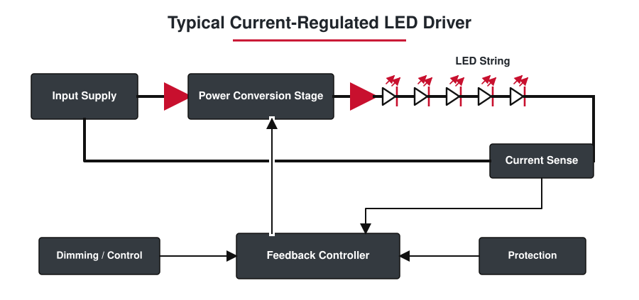
A regulated driver measures a quantity associated with LED current, compares it with an internal or external reference, and adjusts the power stage to reduce the error. In many driver ICs, the LED current flows through a current-sense resistor. The controller changes switch duty cycle or pass-device conduction until the sense voltage reaches the regulation threshold.
The exact equation depends on whether the IC senses peak, valley or average current, and some devices apply an internal gain or offset. The current-setting equation, sense threshold tolerance and resistor power rating must therefore come from the selected component's documentation. A general-purpose switching regulator also needs its voltage feedback loop converted into a current-control loop before it can regulate an LED string properly (TI LED driver design note).
A complete LED driver normally contains several functional blocks:
- An input stage suited to the available AC or DC supply.
- A linear or switching power stage that controls energy delivered to the LEDs.
- Current sensing and a feedback loop.
- A dimming or digital-control interface where brightness adjustment is required.
- Protection for open LEDs, shorted outputs, overtemperature, undervoltage or overvoltage, depending on the application.
LED Driver, LED Power Supply and LED Driver IC
These terms overlap in product listings, but they describe different levels of a design. Treating them as exact synonyms can lead to an incorrect replacement or an incomplete bill of materials.
| Term | Practical meaning | Typical design context |
|---|---|---|
| LED driver | The complete current- or voltage-regulation function that powers an LED load. | Luminaires, automotive lamps, backlights, indicators and displays. |
| LED power supply | Usually a complete AC-DC or DC-DC unit with specified input and output ratings. Some units regulate current; others regulate voltage. | LED strips, modules, architectural lighting and replacement lighting supplies. |
| LED driver IC | An integrated circuit that performs current control, power conversion, channel control or a combination of these functions. | PCB-level designs for lighting, displays, backlights, automotive systems and portable products. |
| LED controller | A control IC that may require an external MOSFET, diode, inductor, current-sense resistor and compensation network. | Higher-power or wide-voltage applications where the external power stage needs to be optimized. |
The following video gives a compact visual introduction to LED electrical behavior, constant-current control, common driver types and brightness adjustment.
Constant-Current vs. Constant-Voltage LED Drivers
A constant-current LED driver regulates one output current while allowing its output voltage to move within a specified compliance range. A driver marked 350 mA and 9 V to 18 V is designed to maintain approximately 350 mA only when the operating voltage of the connected LED string remains inside that range. The voltage range is therefore an operating window, not a choice of fixed output voltages.
A constant-voltage LED driver holds its output at a specified voltage such as 12 V or 24 V. The connected LED strip or module must already contain resistors, current regulators or another method of controlling current. Applying a constant-voltage supply directly to a high-power bare LED without appropriate current limiting can overstress the LED.
| Characteristic | Constant-current driver | Constant-voltage driver |
|---|---|---|
| Regulated quantity | LED current in mA or A | Output voltage, commonly 12 V or 24 V |
| Other output rating | A permissible voltage range | A maximum current or power rating |
| Typical loads | Bare high-power LEDs and series LED strings | LED strips and modules with built-in current limiting |
| Primary compatibility check | Match current and keep the full LED-string voltage inside the driver range | Match voltage and keep total load current below the supply rating |
| Common selection error | Matching wattage while ignoring regulated current | Connecting a load designed for a different voltage |
Series-connected LEDs carry the same current, while their forward voltages add. Parallel strings require more care: regulating only the combined current does not guarantee equal current in each branch. LED forward voltage decreases as junction temperature rises, so a branch carrying more current can heat up, develop a lower forward voltage and take still more current. Separate current sinks, ballast elements or active balancing may be required for parallel strings (Analog Devices technical article).
Linear and Switching LED Driver Circuits
Resistor current limiting
A series resistor can be sufficient for a low-current indicator when the supply, LED forward voltage and ambient temperature occupy a narrow, known range. It is inexpensive and has no switching noise, but current changes with supply voltage and LED forward voltage. The resistor also converts the unused voltage into heat, so this approach becomes inefficient as current or voltage headroom increases.
Linear LED drivers
A linear driver uses a transistor or integrated current sink to regulate LED current. It offers low component count, predictable current and low electromagnetic noise. The driver must retain enough headroom to regulate, and the voltage difference between the supply and LED string is dissipated in the pass device.
This first-order equation is useful before detailed thermal simulation. The LDO Power Dissipation Calculator uses the same voltage-drop-by-current relationship for estimating loss and junction-temperature rise in a linear pass stage. For an LED design, the result still needs to be checked against the driver IC's actual quiescent current, thermal resistance, PCB copper area and temperature derating.
Switching LED drivers
A switching driver transfers energy through an inductor, transformer or switched-capacitor stage. It can provide much higher efficiency across a wide input range, but component selection, control-loop behavior, current ripple, PCB layout and EMI become part of the design. Switching frequency affects inductor size and switching loss, while LED-current ripple can affect light output, camera performance and peak junction temperature.
| Driver approach | Useful operating conditions | Main limitation |
|---|---|---|
| Series resistor | Low-current indicator, stable supply and modest accuracy requirement | Current varies with voltage and temperature |
| Linear current source or sink | Low noise, small voltage difference and moderate LED current | Power loss rises directly with voltage headroom and current |
| Switching regulator | Higher power, wide input range, battery operation or long LED strings | Requires magnetic-component, loop, thermal, layout and EMI design |
Buck, Boost and Buck-Boost LED Driver Topologies
The minimum and maximum supply voltage must be compared with the complete LED-string voltage range. A single typical forward-voltage value is not enough. Include LED binning, temperature, current level, input tolerance and transient conditions before choosing the power topology.
| Topology | When it fits | Important design point |
|---|---|---|
| Buck | The minimum input voltage remains above the maximum LED-string voltage plus required control headroom. | Efficient step-down operation, but dropout must be checked at minimum input and maximum LED forward voltage. |
| Boost | The input remains below the required LED-string voltage. | Open-LED protection and maximum output-voltage rating are critical. |
| Buck-boost | The input can move above and below the LED-string voltage. | Useful for battery and automotive rails, with added power-stage and control complexity. |
| Charge pump | Low-power applications with a limited conversion ratio and little room for an inductor. | Conversion ratios and output power are more restricted than inductor-based topologies. |
| AC-DC LED driver | The driver connects to an AC input and powers a lighting load. | Isolation, power factor, harmonic current, surge, dimmer behavior and applicable safety requirements must be evaluated. |
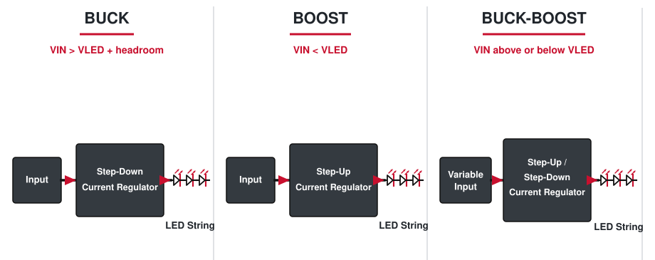
Some LED driver controllers can be configured for more than one topology, while others are optimized for a specific step-down, step-up or floating buck-boost arrangement. Infineon's LED driver portfolio, for example, separates AC-DC, DC-DC, dimming-interface and linear driver functions rather than treating every LED driver as the same circuit class (Infineon LED driver ICs).
The Switching Power Supply Calculator can be used for a preliminary check of conversion ratio, duty cycle, inductance, ripple current and capacitor requirements. Its voltage-regulator results do not replace the LED driver's current-loop equations, current-sense design, output-compliance check or hardware validation.
Calculating LED Driver Voltage, Current and Power
Start with the LED current specified for the required light output and the forward-voltage range at that current. For a series string of N LEDs:
VSTRING,MAX = N × VF,MAX
PLED,MAX ≈ ILED × VSTRING,MAX
Consider an illustrative string of six white LEDs operating at 350 mA. If the applicable LED data gives a forward-voltage range of 2.8 V to 3.3 V at that current and across the intended conditions, the string requires approximately 16.8 V to 19.8 V. Its LED power ranges from about 5.88 W to 6.93 W.
Maximum string voltage: 6 × 3.3 V = 19.8 V
Maximum LED power: 19.8 V × 0.35 A = 6.93 W
With a 24 V input, a buck LED driver may be suitable if the input never falls below the string's maximum voltage plus the driver's required headroom. At 90% conversion efficiency, delivering 6.93 W to the LEDs requires approximately 7.7 W at the input. Component loss, ambient temperature and enclosure conditions still determine the necessary thermal margin.
A linear 350 mA stage operating from 24 V with an 18 V LED string would dissipate approximately 2.1 W in the driver:
That loss may be unacceptable in a small package even though the current is only 350 mA. The calculation shows why input-to-string voltage difference is as important as nominal LED wattage.
PWM Dimming and Analog Dimming
Analog dimming changes the regulated LED current. It does not require the LED current to be periodically interrupted for brightness control, but reducing current can change LED chromaticity and efficacy, especially across a wide dimming range. The driver's specified analog-control range and minimum regulated current determine how far the light output can be reduced cleanly.
PWM dimming switches the LED current between off and a regulated on-state value. When switching transitions are short relative to the PWM period, average LED current is approximately:
PWM can preserve the on-state current and its associated color point, but the design must still check minimum pulse width, rise and fall time, dimming ratio, audible noise, EMI and interaction with cameras. Low PWM frequency or poor timing can produce visible flicker or rolling-band artifacts. Hybrid dimming combines analog current adjustment and PWM over different brightness ranges. TI identifies PWM and analog dimming as the two main methods used in switched-mode LED drivers and discusses different PWM implementations for the power stage (TI dimming techniques).
How the Application Changes LED Driver IC Selection
LED driver ICs cover illumination, backlighting, displays, RGB indicators, camera flash and automotive lighting. These applications can use the same basic current-control principle while requiring very different channel counts, diagnostics, transient ratings and control interfaces.
| Application | Driver requirements that usually dominate |
|---|---|
| General illumination | Efficiency, current accuracy, thermal behavior, dimming compatibility, surge performance and, for AC input, power quality and safety. |
| Automotive exterior lighting | Wide input transients, cold-crank operation, open/short diagnostics, thermal derating, EMC and automotive qualification. |
| LCD or OLED backlight | Boost voltage, multiple-string current matching, high dimming ratio, fault handling and low visible ripple. |
| RGB indicators and decorative lighting | Channel matching, PWM resolution, color mixing, communication interface and total package dissipation. |
| LED matrix or display | Channel count, multiplex timing, constant-current sink compliance, refresh rate, grayscale resolution and data interface. |
| Camera flash or machine vision strobe | Peak pulse current, pulse-width accuracy, recharge time, protection, synchronization and transient thermal limits. |
Manufacturer portfolios commonly separate automotive, backlight, illumination, display and RGB LED drivers because the correct device is defined by the system function as well as current and voltage (TI LED driver portfolio).
LED Driver IC Selection Checklist
- Define the minimum, nominal and maximum input voltage, including startup and transient conditions.
- Determine whether the LED load expects constant current or constant voltage.
- Set the required LED current from the LED's optical, electrical and thermal limits.
- Calculate minimum and maximum series-string voltage at the intended current and temperature range.
- Select buck, boost, buck-boost, linear or another topology from the full input and load range.
- Check current accuracy, ripple and channel-to-channel matching where multiple strings or colors are used.
- Confirm the dimming method, control voltage, logic thresholds, PWM range or digital interface.
- Review open-LED, short-circuit, overvoltage, overcurrent and overtemperature behavior.
- Calculate conduction, switching, current-sense and linear-stage losses at the worst operating points.
- Verify package thermal performance using the real PCB layout, copper area, airflow and ambient temperature.
- Check switching frequency, spread-spectrum options, EMI filters and layout constraints.
- Confirm package, operating temperature, qualification, lifecycle and supply status before design release.
Choosing a Replacement LED Driver
A replacement LED driver must reproduce the electrical operating mode of the original unit. Similar size or equal wattage does not establish compatibility. Record the original driver's input, output, dimming and safety information before comparing replacements.
| Parameter | Replacement rule | Risk if it is ignored |
|---|---|---|
| Input type and range | Match AC or DC input, voltage range and AC frequency where applicable. | The driver may not start, may be damaged or may operate outside its approval conditions. |
| Output mode | Replace constant current with constant current and constant voltage with constant voltage unless the complete LED load is redesigned. | The LED can be overdriven or fail to regulate. |
| Constant-current output | Match the original regulated current. The LED-string voltage must remain inside the new driver's output window. | Excess current shortens LED life; an incorrect voltage window can cause dropout, no start or protection cycling. |
| Constant-voltage output | Match the output voltage. Current and power capacity must meet or exceed the load, subject to minimum-load and dimming requirements. | The wrong voltage can damage the LED module or prevent operation. |
| Power rating | Provide adequate continuous power after temperature derating, but use current and voltage as the primary matching criteria. | A wattage-only match can conceal an incompatible current or voltage rating. |
| Dimming interface | Match phase-cut, 0-10 V, DALI, PWM, resistance or other control method and its electrical levels. | Flicker, limited dimming range, failure to turn off or damage to the control input. |
| Isolation and protection class | Retain the isolation, insulation and applicable safety classification required by the end product. | Electric-shock, fire and compliance risks. |
| Mechanical and environmental ratings | Check connector, polarity, mounting, enclosure, ingress protection, case temperature and ambient-temperature range. | Poor installation, overheating, moisture ingress or reduced service life. |
Common LED Driver Problems and Electrical Checks
| Symptom | Possible driver-side cause | Useful check |
|---|---|---|
| Visible flicker | Incompatible dimmer, excessive output ripple, control-loop instability, low PWM frequency or protection cycling. | Observe input, LED current and dimming signal under the actual load and temperature. |
| No light or repeated restart | Open LED, shorted string, insufficient input voltage, output overvoltage protection or startup-load incompatibility. | Check fault flags, input range, string continuity and required output-voltage window with power removed where appropriate. |
| Low brightness | Incorrect current setting, analog-control input error, thermal foldback or inadequate input power. | Measure regulated LED current and check the current-set resistor, control pin and case temperature. |
| Driver overheating | Excess linear headroom, high switch loss, saturated inductor, poor PCB thermal path or operation beyond derated power. | Calculate losses at worst-case input and load, then verify case and junction-temperature estimates. |
| Uneven parallel strings | LED forward-voltage mismatch, insufficient ballast or poor current-sink matching. | Measure current in each string rather than relying only on total output current. |
| Radio or sensor interference | Fast switching edges, poor current-loop layout, inadequate filtering or unsuitable switching frequency. | Inspect high-di/dt loops, grounding, input/output filters and spectral behavior under maximum load. |
A constant-current driver's open-circuit voltage can rise toward its maximum compliance or protection threshold. Do not evaluate it as if it were a fixed-voltage supply, and do not short or open an energized output unless the manufacturer's test procedure explicitly permits that condition.
Frequently Asked Questions About LED Drivers
What does an LED driver do?
An LED driver controls the electrical power delivered to an LED or LED string. Depending on the load, it regulates current or voltage, converts the available input to the required output range, and may provide dimming, open-LED protection, short-circuit protection and thermal control. High-power bare LEDs normally require regulated current rather than an uncontrolled voltage source.
Is an LED driver the same as a power supply?
An LED driver is a power supply function designed around LED behavior, but the names are not always interchangeable. A product called an LED power supply may provide constant voltage for a 12 V or 24 V LED module, while an LED driver IC may regulate constant current on a PCB. The output mode must be checked rather than inferred from the product name.
Do LEDs need constant current or constant voltage?
Bare LEDs and series strings commonly use a constant-current driver because brightness and electrical stress are governed primarily by forward current. Constant-voltage drivers are used with LED strips or modules designed for a fixed voltage and already equipped with resistors or current-control circuitry. The LED or module specification determines which mode is correct.
Can I replace an LED driver with a higher-wattage driver?
A higher wattage rating alone does not make a replacement compatible. For a constant-current driver, the regulated current must match and the LED-string voltage must fit inside the output range. For a constant-voltage driver, the voltage must match while the current capacity may equal or exceed the load, subject to minimum-load, dimming, thermal and safety requirements.
How do I determine the output voltage for a constant-current LED driver?
Add the minimum and maximum forward voltages of every series-connected LED at the intended current and operating temperatures. The resulting string-voltage range must remain inside the driver's regulated output window, with any required control headroom. Do not multiply a single typical forward voltage without checking production tolerance and temperature dependence.
Why does an LED driver flicker?
Flicker can result from excessive output ripple, incompatible phase-cut or 0-10 V controls, unstable feedback, low-frequency PWM, input-voltage dips, minimum-load problems or repeated fault restart. Measuring LED current together with the input and dimming signals helps separate a driver-control problem from an intermittent LED string or connection.
Does every small indicator LED need a driver IC?
No. A low-current indicator powered from a stable, low-voltage rail can often use a correctly calculated series resistor. A driver IC becomes useful when the supply varies widely, current accuracy matters, several channels must be controlled, dimming or diagnostics are required, or resistor loss and brightness variation are unacceptable.


