
 My Inquiry
 My Account


Hall Effect Sensor: Working Principle, Types, Circuits and Applications
Article Details
A Hall effect sensor is a magnetic sensor that converts a magnetic field into an electrical signal. It can be used for position detection, speed sensing, motor commutation, current measurement, proximity switching, door or lid detection, joystick movement, gear-tooth sensing and automotive control systems. Unlike a mechanical reed switch, a Hall sensor is solid-state and can provide either a digital switching output or a proportional analog output.
Hall effect sensors are common in embedded electronics because they can detect motion or current without direct mechanical contact. A magnet, ferromagnetic target, current-carrying conductor or rotating gear can create the magnetic field that the sensor detects. The correct device depends on output type, magnetic field range, operating point, supply voltage, temperature range, package, target distance, response time and the electrical interface required by the system.
What Is a Hall Effect Sensor?
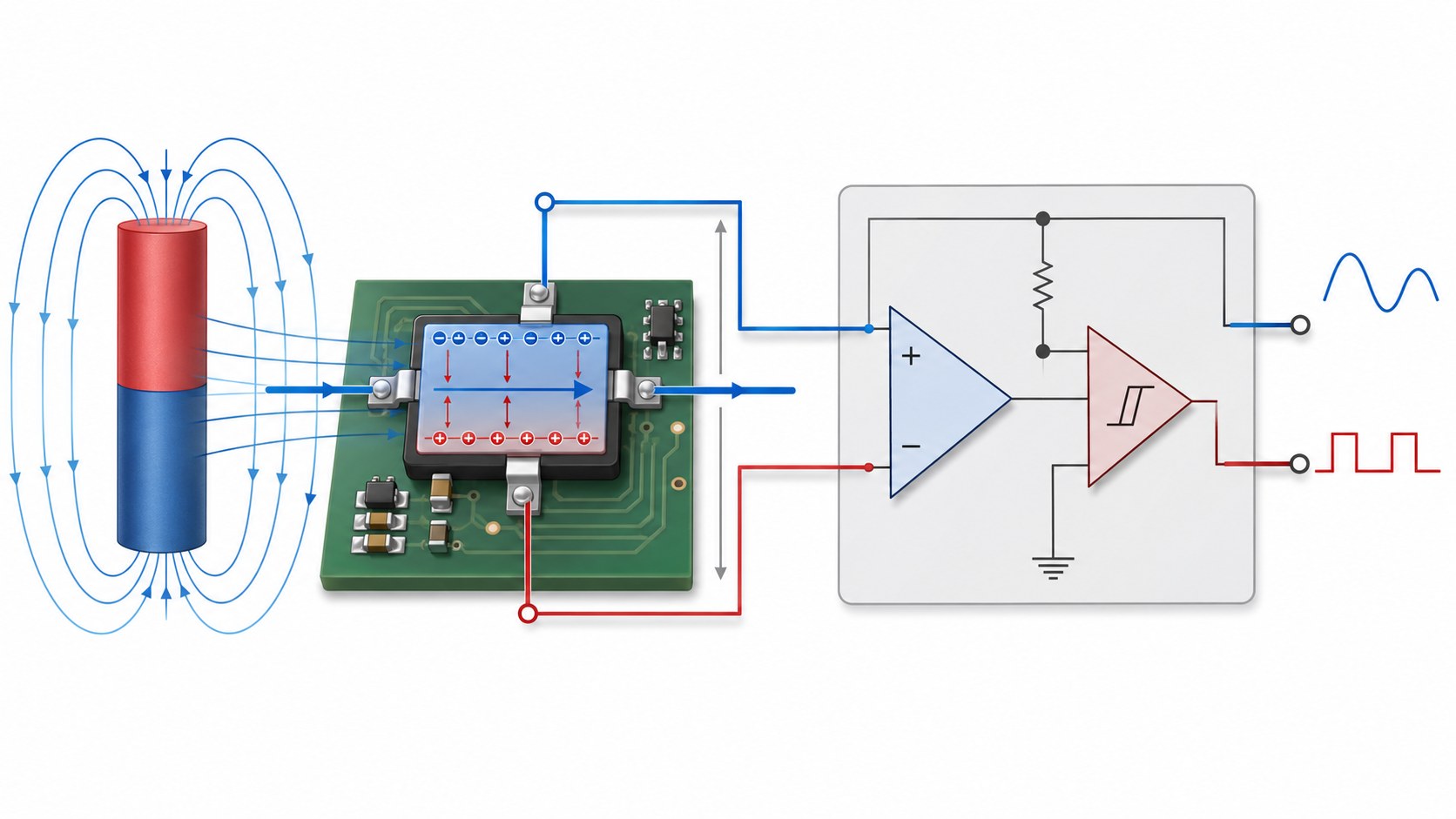
A Hall effect sensor uses the Hall effect to detect magnetic flux density. Inside the device, a Hall element is biased by current. When a magnetic field crosses the Hall element, charge carriers are deflected and a small Hall voltage is generated. Integrated Hall ICs usually include the Hall plate, biasing circuit, amplifier, temperature compensation, comparator or signal-conditioning circuit, and an output stage.
Texas Instruments describes a Hall-effect switch as a digital-output device that switches states based on the magnetic field it senses, while a Hall-effect linear sensor varies its output voltage in proportion to the magnetic field. This difference between digital switching and linear measurement is one of the first decisions in Hall sensor selection. (Texas Instruments Hall-effect sensor overview)
| Sensor Role | What the Hall Sensor Detects | Typical Output |
|---|---|---|
| Proximity detection | Magnet moving near the sensor | Digital on/off signal |
| Linear position sensing | Magnetic field strength changes with distance or angle | Analog voltage, PWM or digital data |
| Speed sensing | Rotating magnet, gear tooth or magnetic target | Pulse output |
| Current sensing | Magnetic field created by current flow | Analog voltage, differential output or isolated current sensor output |
| BLDC motor commutation | Rotor magnet position | Digital latch outputs |
How Does a Hall Effect Sensor Work?
A Hall effect sensor starts with a current-biased semiconductor element. When no magnetic field is present, the output of the Hall plate remains near its internal baseline. When a magnetic field passes through the Hall element, charge carriers shift sideways and create a small voltage difference. The IC amplifies this signal and converts it into a usable output.
The output format depends on the sensor type. A digital Hall switch compares the sensed magnetic field against an internal threshold and changes output state when the operate point is reached. A linear Hall effect sensor produces an output that changes with field strength. A latch changes state with one magnetic polarity and resets with the opposite polarity. A current sensor uses the magnetic field around a conductor to estimate current without placing the measurement circuit directly in series with the load.
Hall Effect Sensor Working Principle Video
The video above from Texas Instruments gives a practical introduction to Hall-effect position sensing, including magnetic-field basics, Hall IC behavior and common Hall sensor types. It is a useful visual reference before comparing digital switches, latches, linear Hall sensors and current-sensing applications.
Linear, Digital, Latch and Omnipolar Hall Sensors
Hall effect sensors are not all the same. A digital Hall sensor works like a magnetic switch. A linear Hall sensor provides proportional magnetic-field information. A latching Hall sensor is often used with alternating magnetic poles in motors. An omnipolar Hall sensor can detect either north or south magnetic poles and is commonly used in simple open/close or lid-detection systems.
| Hall Sensor Type | Output Behavior | Typical Applications | Design Notes |
|---|---|---|---|
| Digital Hall switch | Changes output state when magnetic field crosses an operate threshold. | Proximity detection, door sensing, limit switch, magnet presence detection, speed pulse. | Check operate point, release point, hysteresis, output type and pull-up requirement. |
| Linear Hall effect sensor | Output changes proportionally with magnetic field strength. | Position sensing, displacement, joystick, current measurement, angle sensing. | Check sensitivity, output range, offset, ADC resolution, noise and temperature drift. |
| Latching Hall sensor | Switches with one magnetic polarity and resets with the opposite polarity. | BLDC motor commutation, rotor position, magnetic encoder pulse generation. | Requires alternating magnetic poles or a rotating magnetic target. |
| Omnipolar Hall switch | Detects either north or south pole. | Lid detection, wake/sleep switch, door open/close sensing, consumer electronics. | Useful when magnet orientation may vary during assembly. |
| Hall current sensor | Measures magnetic field created by current flow. | Battery systems, motor drives, inverters, chargers, power supplies, solar and industrial equipment. | Check current range, bandwidth, isolation, offset, temperature drift and conductor layout. |
Hall Effect Sensor Pinout and Basic Circuit
Many small Hall sensors use three pins: supply, ground and output. This does not mean all Hall sensors share the same pinout. The package orientation, output type, magnetic sensing axis and pin assignment must always be checked in the datasheet. Digital Hall sensors often use an open-drain or open-collector output that needs a pull-up resistor. Linear Hall sensors usually provide an analog voltage or PWM output that is read by an ADC, timer input or signal-conditioning stage.
| Circuit Item | Purpose | Design Check |
|---|---|---|
| VCC | Sensor supply voltage. | Match sensor operating range with MCU logic level, 3.3 V or 5 V system rail. |
| GND | Sensor reference and return path. | Use a clean ground reference for low-noise analog measurement. |
| OUT | Digital switch output, analog voltage output, PWM output or serial output depending on sensor type. | Check whether the output needs a pull-up resistor, ADC input, timer capture or interface circuit. |
| Pull-up resistor | Required for many open-drain/open-collector digital Hall outputs. | Choose value based on supply voltage, output current, wiring length and speed requirement. |
| Decoupling capacitor | Reduces supply noise at the sensor. | Place close to the sensor supply pins, especially near motors or switching converters. |
| Input filter | Reduces noise on analog or long-wire signals. | Filter bandwidth must not remove real speed, position or current information. |
Linear Hall Effect Sensor and ADC Reading
A linear Hall effect sensor is used when the system needs more than a simple near/far magnetic switch. It can estimate magnetic field strength, displacement, angle, joystick position, current level or the movement of a magnet relative to a sensor. The output may be centered around mid-supply and move higher or lower depending on magnetic polarity and field strength.
When a linear Hall sensor is connected to a microcontroller ADC, the ADC resolution and reference voltage determine how much magnetic-field change can be observed. If the sensor output changes only a few millivolts across the useful movement range, a low-resolution ADC or noisy reference may hide the signal. The ADC Resolution Calculator can be used to estimate LSB size, quantization error, ideal ADC code and usable input range before selecting ADC resolution or reference voltage.
| Linear Hall Design Parameter | What to Check |
|---|---|
| Sensitivity | Output change per magnetic flux density, usually specified in mV/mT, mV/G, LSB/mT or PWM duty response. |
| Offset voltage | Output voltage when no magnetic field is applied; often near half supply in bipolar linear sensors. |
| Output swing | Minimum and maximum output voltage under expected field strength and supply range. |
| ADC resolution | Smallest voltage step the MCU can measure; compare this with the Hall sensor signal change. |
| Noise and bandwidth | High bandwidth may capture fast movement but can increase output noise; filtering may be required. |
| Temperature drift | Offset and sensitivity can shift with temperature, especially in automotive and industrial environments. |
Digital Hall Effect Sensor and A3144 Example
A digital Hall effect sensor is used when the circuit only needs a logic-level magnetic detection result. When the magnet is close enough and the magnetic field exceeds the operate point, the output switches. When the magnetic field drops below the release point, the output returns to its previous state. Hysteresis prevents unstable switching near the threshold.
A3144-type Hall effect sensors are commonly used in Arduino experiments, magnet proximity detection and simple speed sensing examples. They are usually treated as digital Hall switches rather than linear magnetic measurement devices. The exact pinout, operate point, output structure and voltage range still need to be checked in the specific manufacturer datasheet because many A3144-compatible parts are sourced from different suppliers.
| Digital Hall Item | Design Meaning |
|---|---|
| Operate point | Magnetic field level where the sensor changes output state. |
| Release point | Magnetic field level where the sensor returns to the inactive state. |
| Hysteresis | Difference between operate and release levels; prevents output chatter near threshold. |
| Open-drain / open-collector output | Requires a pull-up resistor to create a logic-high level. |
| Magnetic polarity | Some devices respond only to one pole; omnipolar versions can detect either pole. |
Hall Effect Sensor Arduino Circuit
An Arduino Hall effect sensor circuit usually uses either a digital Hall switch connected to a digital input or a linear Hall sensor connected to an analog input. A digital Hall switch can detect a magnet passing by a wheel, fan, shaft or door. A linear Hall sensor can report approximate magnet distance or field strength through the ADC.
| Arduino Use Case | Sensor Type | Connection Method | Design Check |
|---|---|---|---|
| Magnet near/far detection | Digital Hall switch | VCC, GND and OUT to digital input with pull-up if required. | Check 3.3 V / 5 V compatibility and magnetic polarity. |
| RPM or speed pulse | Digital Hall switch or latch | OUT to interrupt-capable digital input. | Check pulse frequency, pull-up strength and debounce/filtering. |
| Magnet distance or joystick position | Linear Hall sensor | Analog output to ADC input. | Check ADC resolution, reference voltage, offset and signal range. |
| Current sensing module | Hall current sensor | Analog output to ADC input or module-specific interface. | Check zero-current offset, gain, current range and noise filtering. |
Signal Conditioning and Noise Filtering
Hall sensor signals can be affected by motor switching, long wires, weak pull-up resistors, poor grounding, noisy power supplies or magnetic interference from nearby conductors. Digital Hall sensors may produce false pulses if the wiring is noisy. Linear Hall sensors may need filtering if the measured magnetic field changes slowly but the circuit operates near high-current switching devices.
A small RC low-pass filter may help reduce noise on an analog Hall output, but the cutoff frequency must remain high enough for the required response time. The RC Low-Pass Filter Calculator can help estimate the cutoff frequency before selecting resistor and capacitor values for Hall sensor signal conditioning.
| Noise Source | Possible Effect | Mitigation |
|---|---|---|
| Motor or relay switching | False digital pulses or analog output spikes. | Use proper grounding, local decoupling, filtering and shielded routing where needed. |
| Long sensor cable | Noise pickup, slow edges or voltage drop. | Use correct pull-up value, twisted pair, shielding or differential/conditioned output where appropriate. |
| Weak pull-up resistor | Slow digital transitions at higher pulse frequency. | Adjust pull-up value while respecting output current limits. |
| ADC reference noise | Unstable readings from linear Hall sensors. | Use a clean reference, local bypassing and averaging if the signal bandwidth allows. |
| External magnetic field | Offset shift or false detection. | Review magnet placement, shielding, sensor orientation and distance to high-current conductors. |
Hall Effect Current Sensor
A Hall effect current sensor measures current by detecting the magnetic field generated around a current-carrying conductor. This allows current measurement without forcing the signal electronics to share the same electrical path as the load. Hall current sensors are useful for DC current measurement, battery systems, motor drives, inverters, solar power electronics, EV chargers, industrial equipment and high-side current sensing.
Hall current sensing is often compared with shunt resistor sensing. A shunt resistor is simple and precise when properly designed, but it creates voltage drop and power dissipation in the current path. A Hall current sensor can reduce insertion loss and support isolation, but it has offset, drift, bandwidth and magnetic layout considerations. Before choosing a Hall sensor or shunt-based circuit, engineers can use the Current Sense Resistor & Shunt Calculator to estimate shunt voltage, resistor power, amplifier output and tolerance/TCR error for the alternative shunt approach.
| Current Sensing Method | Strength | Trade-Off |
|---|---|---|
| Hall current sensor | Can measure DC current, supports isolation, low insertion loss in many designs. | Offset, temperature drift, bandwidth, magnetic layout and cost must be checked. |
| Shunt resistor | Simple, low cost, high accuracy possible with Kelvin layout and amplifier. | Creates voltage drop and power dissipation; isolation requires extra circuitry. |
| Current transformer | Good for AC current and isolation. | Cannot measure DC steady-state current directly. |
| Rogowski coil | Useful for high-current AC and fast transients. | Requires integration and is not suitable for DC steady-state measurement. |
Hall Effect Zero Speed Sensor and Speed Detection
A Hall effect speed sensor detects repeated magnetic field changes from a rotating magnet, pole wheel, gear tooth or ferromagnetic target. Each passing target creates a pulse, and the controller converts pulse frequency into speed, RPM or position index. Unlike some passive variable reluctance sensors, an active Hall sensor can detect target presence at zero or very low speed if the magnetic field and sensor structure support that operating mode.
Zero-speed detection is useful in wheel-speed systems, crankshaft or camshaft position sensing, gear tooth sensing, conveyor feedback, motor speed sensing and index detection. The sensor, magnet and target geometry must be designed together. Air gap, target material, tooth shape, magnet strength, vibration and operating temperature can all change the output margin.
| Speed Sensor Parameter | Design Impact |
|---|---|
| Air gap | Large gap reduces magnetic signal; too small a gap may create mechanical clearance risk. |
| Target material | Ferromagnetic targets and magnets create different sensing requirements. |
| Pulse frequency | Determines output switching speed and controller timer/interrupt requirements. |
| Zero-speed capability | Allows target position detection even when movement stops. |
| Temperature range | Magnet strength and sensor thresholds can shift with temperature. |
Hall Effect Sensor in Cars
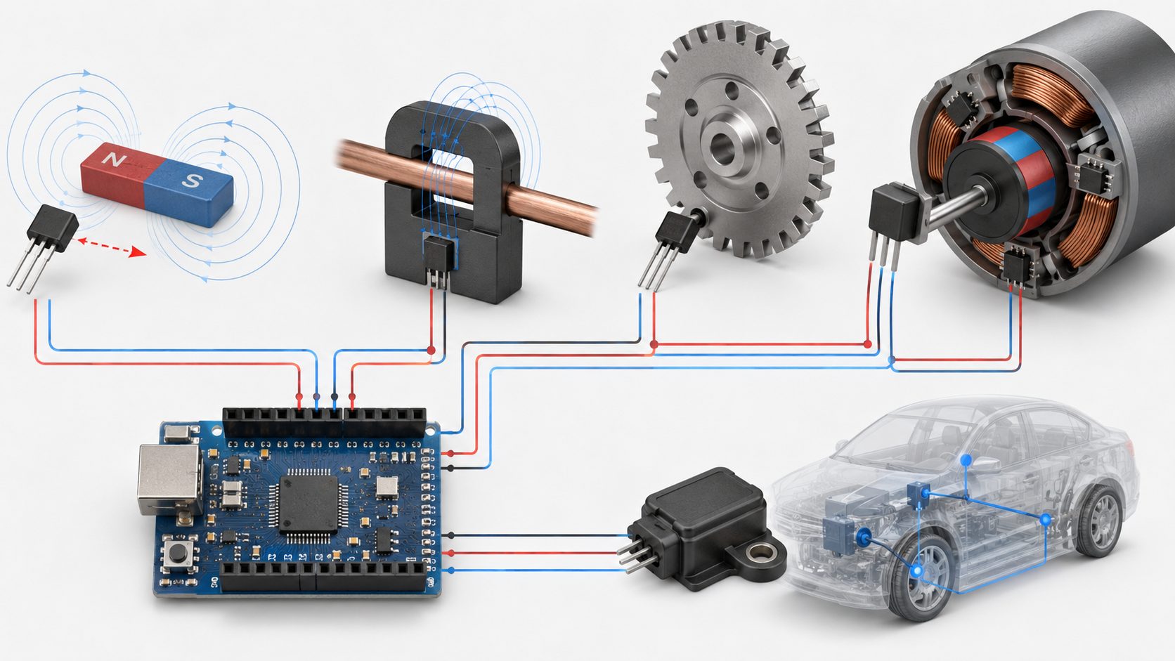
Hall effect sensors are widely used in vehicles because they can provide non-contact sensing in dusty, vibrating and temperature-changing environments. Automotive applications include wheel speed, crankshaft position, camshaft position, pedal position, throttle position, door or latch detection, seat position, BLDC motor feedback, battery current sensing and power electronics monitoring.
Automotive Hall sensor selection usually requires closer review than hobby circuits. The design may need automotive-grade qualification, extended temperature range, reverse battery tolerance, electromagnetic immunity, supply transient protection, diagnostic capability and stable operation across magnet aging and mechanical tolerance.
| Automotive Application | Hall Sensor Function | Selection Focus |
|---|---|---|
| Wheel speed | Detects rotation pulses from a target wheel or magnetic encoder. | Zero-speed detection, air gap, temperature, vibration and signal integrity. |
| Crankshaft / camshaft position | Provides timing reference for engine control. | Speed range, target geometry, jitter, temperature and EMC robustness. |
| Pedal / throttle position | Measures angular position with a magnet and linear or angle sensor. | Linearity, redundancy, diagnostics and safety architecture. |
| Battery current sensing | Measures charge/discharge current without direct low-side shunt insertion. | Current range, isolation, offset drift, bandwidth and thermal stability. |
| BLDC motors | Detects rotor position for commutation. | Latch behavior, magnetic pole arrangement, timing and temperature range. |
Hall Effect Sensor Applications
Hall sensors are selected when magnetic, non-contact or isolated sensing provides an advantage over mechanical, optical or resistive methods. They can operate through dust, plastic walls, sealed housings and non-magnetic barriers when the magnet and sensor are correctly positioned.
| Application Area | Sensor Type Often Used | Key Design Parameter |
|---|---|---|
| Door, lid or cover detection | Digital or omnipolar Hall switch | Magnet placement, operate/release point and sleep current. |
| Joystick and lever position | Linear or angle Hall sensor | Linearity, ADC resolution, mechanical tolerance and calibration. |
| Fan, motor or gear speed | Digital Hall switch, latch or gear-tooth sensor | Pulse frequency, air gap, output timing and magnetic target design. |
| Power current measurement | Hall current sensor | Current range, offset, bandwidth, isolation and conductor layout. |
| BLDC motor commutation | Latching Hall sensor | Rotor magnet pole spacing, sensor placement and commutation timing. |
| Automotive position sensing | Linear, latch, switch or 3D magnetic sensor | Temperature range, EMC, diagnostics and reliability qualification. |
Hall Effect Sensor vs Other Sensors
A Hall effect sensor is not the only way to detect position, current or speed. The right choice depends on target material, power budget, required accuracy, environmental exposure, isolation, response speed and cost. Hall sensors are strongest when magnetic non-contact detection, DC current sensing or sealed operation is useful.
| Comparison | Hall Sensor Advantage | Other Sensor Advantage |
|---|---|---|
| Hall sensor vs reed switch | Solid-state, no mechanical contacts, suitable for high-cycle operation. | Reed switches are simple and can be fully passive. |
| Hall sensor vs optical sensor | Works through dust, plastic and sealed housings when magnetic field is adequate. | Optical sensors can provide high resolution when a clean optical path is available. |
| Hall current sensor vs shunt resistor | Can measure DC current with isolation and low insertion loss in many designs. | Shunt circuits can provide high accuracy and low cost when power loss is acceptable. |
| Hall sensor vs variable reluctance sensor | Active Hall sensors can support low-speed or zero-speed detection. | Variable reluctance sensors are rugged and simple for high-speed ferromagnetic targets. |
| Hall sensor vs magnetoresistive sensor | Widely available, robust and cost-effective for many magnetic sensing tasks. | Magnetoresistive sensors may offer higher sensitivity or angle accuracy in some designs. |
How to Select a Hall Effect Sensor
Hall sensor selection should be based on the physical measurement first, then the electrical interface. A proximity switch does not need the same parameters as a current sensor. A linear position sensor does not need the same output behavior as a BLDC latch. A speed sensor must be checked against target frequency, air gap and zero-speed behavior.
| Selection Item | What to Check in the Datasheet |
|---|---|
| Sensor type | Digital switch, latch, omnipolar, linear, 2D/3D magnetic sensor or Hall current sensor. |
| Supply voltage | Operating range, 3.3 V / 5 V compatibility, automotive load transient requirements if applicable. |
| Output type | Open-drain, push-pull, analog voltage, PWM, frequency, SENT, I2C, SPI or differential output. |
| Magnetic threshold | Operate point, release point, hysteresis, magnetic polarity and sensitivity tolerance. |
| Linear response | Sensitivity, offset, output swing, linear range, ratiometric behavior and temperature drift. |
| Bandwidth and response time | Maximum signal frequency for speed sensing, current transients or motor feedback. |
| Current range and isolation | For Hall current sensors, check rated current, overcurrent, isolation voltage, creepage and clearance. |
| Package and orientation | Sensing axis, leaded/SMD package, mechanical alignment, PCB placement and magnet direction. |
| Temperature range | Industrial or automotive range, offset drift, sensitivity drift and magnet temperature behavior. |
| Qualification | AEC-Q grade, functional safety documentation, PPAP support or industrial reliability data when required. |
Hall Effect Sensor Datasheet Checklist
The datasheet is the final reference for pinout, magnetic behavior and output limitations. For sensors sourced across different manufacturers, even a common part name may not guarantee the same switching threshold, output stage, package orientation or temperature behavior.
| Datasheet Field | Design Use |
|---|---|
| Pin configuration | Prevents reversed supply, wrong output wiring or incorrect package orientation. |
| Magnetic operate and release points | Defines required magnet strength, distance and switching margin. |
| Sensitivity and offset | Required for linear Hall output scaling and calibration. |
| Output stage | Determines pull-up resistor, load current, logic level and interface method. |
| Response time or bandwidth | Sets maximum useful speed for pulse, motor or current sensing applications. |
| Temperature characteristics | Shows drift and reliability under automotive or industrial temperature range. |
| Recommended circuit | Shows decoupling, pull-up, filtering, output load and layout recommendations. |
| Package drawing and sensing axis | Controls magnet orientation, air gap, PCB layout and mechanical placement. |
Frequently Asked Questions
What is a Hall effect sensor?
A Hall effect sensor is a magnetic sensor that converts magnetic field changes into an electrical signal. It is used for position, speed, proximity, current and motor feedback sensing.
How does a Hall effect sensor work?
A current-biased Hall element generates a small voltage when exposed to a magnetic field. The sensor IC amplifies and processes that signal into a digital switch output, analog voltage, PWM output or current-sensor signal.
What is the difference between linear and digital Hall sensors?
A linear Hall sensor produces an output proportional to magnetic field strength. A digital Hall sensor switches between logic states when the magnetic field crosses an operate or release threshold.
Can a Hall effect sensor measure current?
Yes. A Hall current sensor measures the magnetic field generated by current flow. It can measure DC current and can provide isolation between the high-current path and measurement electronics.
Can Hall sensors detect speed?
Yes. A Hall sensor can generate pulses from a rotating magnet, pole wheel or gear target. The controller can calculate RPM or speed from the pulse frequency.
What is a Hall effect zero speed sensor?
A zero-speed Hall sensor can detect target position or magnetic field even when the target is stopped or moving very slowly, depending on sensor and target design.
How do you connect a Hall effect sensor to Arduino?
A digital Hall switch usually connects to a digital input with VCC, GND and output, plus a pull-up resistor if required. A linear Hall sensor connects to an analog input so the ADC can read the output voltage.
Is A3144 a Hall effect sensor?
A3144 is commonly used as a digital Hall effect switch in Arduino and proximity detection examples. Exact specifications depend on the specific manufacturer datasheet.
Does a Hall sensor need a magnet?
Most Hall proximity, position and speed sensors require a magnet or magnetic target. Hall current sensors detect the magnetic field produced by current flow and may not require a separate magnet.
Can a Hall sensor detect AC and DC current?
Hall current sensors can measure DC current and, depending on bandwidth and sensor design, AC current as well. Current transformers are generally used for AC only and cannot measure steady DC current directly.
What should be checked in a Hall effect sensor datasheet?
Check supply voltage, output type, pinout, magnetic operate/release point, sensitivity, offset, bandwidth, temperature range, package orientation, sensing axis and qualification status.
Engineering Summary
Hall effect sensors provide magnetic, non-contact sensing for position, speed, current, proximity and motor-control applications. The correct device type depends on whether the system needs a digital switch, linear measurement, latching motor feedback, omnipolar detection, zero-speed sensing or isolated current measurement.
For engineering selection, the main checks are output type, magnetic threshold or sensitivity, supply voltage, signal conditioning, ADC resolution, current range, bandwidth, temperature drift, package orientation, target geometry and datasheet limits. Arduino examples are useful for basic learning, but production designs need magnetic margin, electrical interface review, noise filtering, thermal behavior and application-level validation.


