
 My Inquiry
 My Account


Obsolete Electronic Components: How to Source and Evaluate Replacements
Article Details
An obsolete electronic component is an exact orderable part number that its manufacturer no longer produces or accepts for new orders. Inventory may still exist at distributors, brokers, contract manufacturers, repair depots or equipment owners, but stock availability does not return the part to active production.
The practical response depends on the equipment, remaining production demand, service obligation and redesign authority. A traceable original part may be the lowest-risk answer for a short repair program. A qualified alternate may be better for continued production. A circuit redesign becomes necessary when no defensible supply or compatible replacement remains.
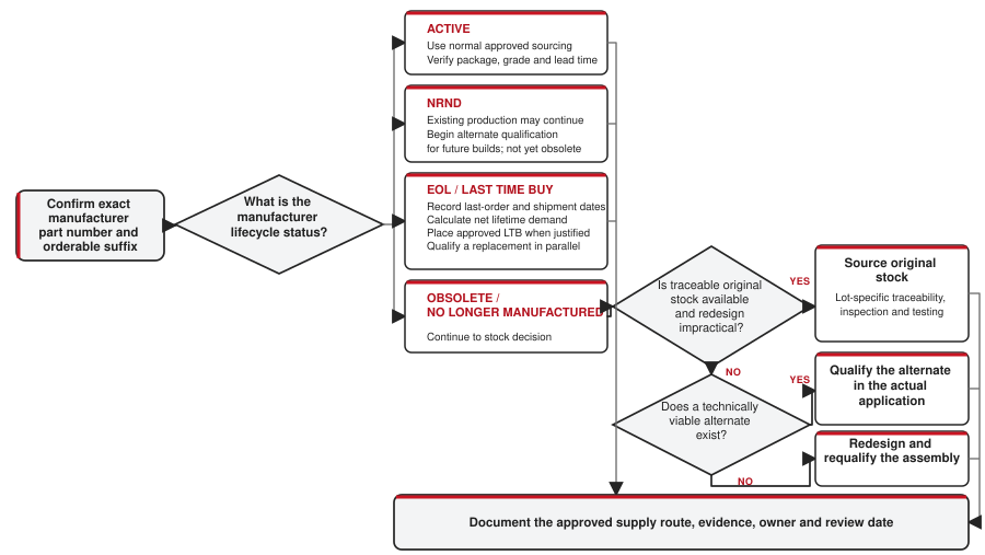
Confirm the Lifecycle Status of the Exact Part Number
Start with the complete manufacturer part number, including package, temperature grade, qualification suffix, packing code and revision-dependent options. A family page can remain active while one package or temperature variant is obsolete. Distributor search results may also merge active and discontinued variants under a shortened description.
| Status | What it means | Immediate action |
|---|---|---|
| Active | The manufacturer accepts production orders for the orderable device. | Check lead time, lifecycle commitment and approved second sources. |
| NRND | Not recommended for new designs. Existing customers may still be able to order it; a discontinuance decision is not implied by the label alone. | Avoid adding it to a new platform. Begin alternate analysis for long-life programs. |
| EOL / Last Time Buy | The discontinuance process has started and the notice defines final order and shipment dates. | Validate demand, place approved final orders and start replacement qualification. |
| Obsolete / No Longer Manufactured | Production and normal factory ordering have ended. | Choose controlled original-part sourcing, alternate qualification or redesign. |
Use the manufacturer product page and discontinuance notice as the lifecycle authority. Record the notice number, publication date, affected orderable codes, last-time-buy date, last-time-ship date and any manufacturer-recommended replacement. The terminology differs by manufacturer: for example, NXP separates EOL from "No Longer Manufactured," while other manufacturers use "Obsolete" for the final state.
A discontinuance notice belongs in the engineering change process as well as the purchasing inbox. The Product Change Notification guide explains how PCN, PDN, EOL, LTB and LTS records should move through purchasing, engineering and quality review.
Choose a Supply Strategy Before Requesting Quotes
The response should cover the remaining equipment life rather than solve only the next shortage. Establish annual production, service demand, contract obligations, redesign lead time, certification constraints and the date at which the assembly will leave production.
Use at least a base forecast and a credible high-demand case. Include manufacturing yield loss, repair consumption and the expected attrition of stored material. "Usable stock" excludes quarantined lots, damaged packaging and inventory whose identity or storage history cannot meet the program's requirements.
| Strategy | Best fit | Main exposure | Required control |
|---|---|---|---|
| Buy active factory material | The status or suffix was misidentified, or a valid active orderable version remains. | Incorrect package, grade or packing code. | Confirm the exact manufacturer part number. |
| Last-time buy | Demand is forecastable and the official order window is still open. | Excess inventory, cash tied up, storage life and forecast error. | Approved lifetime-demand model and storage plan. |
| Bridge buy | A replacement or redesign is underway but will not be ready before existing stock runs out. | Schedule slip consumes the bridge quantity. | Milestone-based demand review and contingency stock. |
| Source original obsolete stock | Repair, certification or documentation locks the design to the original device. | Traceability, storage, counterfeit and mixed-lot risk. | Supplier qualification plus lot-specific inspection and testing. |
| Qualify an alternate | A candidate can meet circuit and program requirements without a board redesign. | Hidden electrical, timing, firmware or qualification differences. | Written comparison and application-level validation. |
| Redesign | No sustainable compatible device exists or the legacy function is no longer supportable. | Engineering effort, validation, certification and tooling changes. | Controlled design-change and requalification plan. |
Build the Replacement Requirement from the Circuit
The old data sheet is the starting point. It does not contain every requirement imposed by the product. Extract the behavior that the existing design actually uses from the schematic, layout, firmware, production test, qualification records and field-return history.
Before comparing candidates, assemble this baseline:
- approved manufacturer part number and all suffixes;
- data-sheet revision, errata and application notes used in the design;
- schematic connections, external component values and PCB footprint;
- measured supply, signal, thermal and timing conditions at the device pins;
- firmware dependencies, register settings and startup sequence;
- temperature, vibration, humidity, isolation or safety requirements;
- qualification level, compliance documentation and customer-specific approvals;
- known production margins and failure modes.
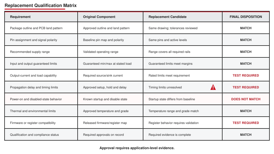
A useful replacement specification distinguishes mandatory limits from preferences. An exact body width may be mandatory for a fixed footprint; lower standby current may be desirable but irrelevant to approval. This separation keeps the search wide without weakening the requirements that protect the design.
Check Form, Fit and Function Separately
"Form, fit and function" is a convenient heading, but each category contains several independent checks. Two parts can share a package name and pin count while differing in exposed-pad geometry, pin assignment, logic polarity or thermal performance.
| Category | Items to compare | Common hidden mismatch |
|---|---|---|
| Package and footprint | Package drawing, pitch, body width, lead span, pin 1, exposed pad, coplanarity and board land pattern. | The same package label covers narrow and wide body versions. |
| Pinout | Pin numbers, no-connect pins, internally connected pads, polarity and multifunction pins. | A reserved pin on the old part becomes an active input on the candidate. |
| Assembly | MSL, peak reflow temperature, finish, solderability, package height and reel orientation. | The electrical alternate needs a different stencil or handling process. |
| Basic function | Truth table, gain, transfer function, resolution, channel count, direction and output state. | Enable or reset polarity differs. |
| Exceptional behavior | Power-on state, disabled outputs, fault response, brownout behavior and illegal input states. | The normal operating mode matches, but startup drives a previously inactive load. |
Three Real Replacement Cases
Replacement work becomes easier to control when the exact old and new orderable codes are compared. The following cases represent three different situations: a packing-code change, a manufacturer-designated functional upgrade and a cross-brand board-level replacement candidate.
Case 1: SN75C185DW to SN75C185DWR - Same Device, Different Carrier
Texas Instruments lists SN75C185DW as obsolete and identifies SN75C185DWR as an active drop-in replacement. Both orderable codes refer to the same SN75C185 function in the 20-pin DW SOIC package and the same 0°C to 70°C operating range. The material difference is the shipping carrier: DW was supplied in tubes of 25, while DWR is supplied on a large tape-and-reel quantity of 2,000.
| Check | SN75C185DW | SN75C185DWR | Engineering decision |
|---|---|---|---|
| Lifecycle | Obsolete | Active | Use the active orderable code for new purchasing records. |
| Device and package | SN75C185, DW, 20 pins | SN75C185, DW, 20 pins | No circuit or PCB change is indicated by the orderable-code change. |
| Temperature range | 0°C to 70°C | 0°C to 70°C | No temperature-grade change. |
| Carrier | 25 pieces per tube | 2,000 pieces per large reel | Confirm feeder, minimum-order quantity, reel handling and purchasing-unit changes. |
Case 2: TPS54618QRTERQ1 to TPS54618CQRTERQ1 - Manufacturer-Designated Upgrade
TI marks TPS54618QRTERQ1 obsolete and names TPS54618CQRTERQ1 as an active drop-in replacement with upgraded functionality. Both are automotive synchronous buck converters rated for a 2.95 V to 6 V input, 6 A output, switching frequencies up to 2 MHz and a -40°C to 125°C ambient range. Both use the 16-pin, 3 mm × 3 mm RTE WQFN package.
The manufacturer designation establishes a strong candidate; it does not remove the application checks expected for a power converter. Review the complete pin table and exposed-pad drawing, feedback and compensation network, inductor and capacitor limits, switching-frequency setting, startup into pre-bias, enable and UVLO thresholds, power-good behavior, current limit, fault recovery and thermal margin.
| Validation item | Why it remains necessary | Useful test |
|---|---|---|
| Static regulation | Reference and feedback behavior must meet the product rail tolerance. | Measure output accuracy at minimum and maximum input, load and temperature. |
| Loop response | The installed L-C network and compensation determine stability and transient performance. | Measure load transients; perform loop-response testing where the program requires it. |
| Startup and sequencing | Pre-bias, soft-start, enable and power-good behavior can affect downstream devices. | Capture startup, shutdown, brownout and repeated power-cycle waveforms. |
| Protection and thermals | Current-limit and thermal behavior matter during abnormal load conditions. | Exercise overload and fault recovery while monitoring temperature and output response. |
| Qualification records | The replacement changes the approved orderable part even within the same manufacturer. | Update AEC-Q100 evidence, PPAP or customer approval records as applicable. |
Case 3: Nexperia 74HC00D,652 to TI CD74HC00M96 - Cross-Brand Direct-Replacement Candidate
Nexperia classifies 74HC00D,652 as withdrawn/end-of-life. TI lists CD74HC00M96 as active. Both devices implement four independent 2-input NAND gates, operate from 2 V to 6 V and use a 14-pin narrow-body SOIC with 1.27 mm lead pitch.
The logic pin assignment is the same: 1A, 1B and 1Y occupy pins 1 through 3; the second gate uses pins 4 through 6; pin 7 is ground; the third and fourth gates use pins 8 through 13; and pin 14 is the positive supply. The Nexperia SOT108-1 and TI D0014A package drawings also share the primary 8.55–8.75 mm body length, 3.8–4.0 mm body width and 5.8–6.2 mm lead span. These points make the TI device a credible direct board-replacement candidate.
| Requirement | Nexperia 74HC00D | TI CD74HC00M96 | Disposition |
|---|---|---|---|
| Function and pinout | Four 2-input NAND gates; standard 14-pin assignment | Four 2-input NAND gates; same 14-pin assignment | Form and basic function match. |
| Package | SOT108-1 SO14, 1.27 mm pitch | D0014A SOIC, 1.27 mm pitch | Primary dimensions align; overlay both package and land-pattern drawings before release. |
| Supply and temperature | 2 V to 6 V; -40°C to 125°C | 2 V to 6 V; -55°C to 125°C | The TI published ranges cover the Nexperia operating envelope. |
| 4.5 V input limits | VIH ≥ 3.15 V; VIL ≤ 1.35 V | VIH ≥ 3.15 V; VIL ≤ 1.35 V | DC input thresholds align at the stated supply. |
| Loaded output limits at 4.5 V | VOH ≥ 3.7 V at -4 mA; VOL ≤ 0.4 V at 4 mA over the wide temperature range | VOH ≥ 3.7 V at -4 mA; VOL ≤ 0.4 V at 4 mA over the wide temperature range | Check the actual fan-out and capacitive load; the published limits align for this condition. |
| Propagation delay at 4.5 V, 50 pF | 27 ns maximum from -40°C to 125°C | 27 ns maximum from -55°C to 125°C | The stated worst-case limit aligns; verify edge-rate and race sensitivity on the board. |
Nexperia also lists 74HC00D,653 as active, so a same-manufacturer packing transition may be the simpler route. The TI part becomes useful when the approved-vendor strategy calls for a second manufacturer or when the required supply route favors TI. In either case, compare the current data-sheet revisions, input transition-rate limit, leakage, output loading, power dissipation, ESD rating, material declarations and change-notification terms.
Compare Guaranteed Electrical Limits
Use minimum and maximum limits at the intended supply, temperature and load. Typical values describe representative behavior and are unsuitable for a worst-case compatibility decision. Absolute-maximum ratings define stress boundaries; they are not normal operating targets.
Digital logic
For logic devices, compare recommended supply range, input-voltage limits, VIH, VIL, VOH, VOL, input current, output current and input transition-time requirements. Confirm every direction across a mixed-voltage interface.
A familiar trap appears when replacing legacy TTL logic. A 5 V 74HCT input uses TTL-compatible thresholds, while a 5 V 74HC input generally requires a higher guaranteed HIGH level. A footprint and Boolean function match therefore does not make HC an automatic substitute for LS or HCT. The TTL and CMOS logic-level comparison shows how to calculate the HIGH- and LOW-state noise margins from guaranteed limits.
Analog, Interface and Power Devices
For an op amp or data converter, check input common-mode range, output swing, offset, bias current, noise, bandwidth, slew rate, settling, stability with the existing load and reference behavior. For a regulator or power switch, add dropout, transient response, current limit, switching frequency, compensation, safe operating area, thermal resistance, protection thresholds and fault recovery.
A candidate with a wider headline voltage range can still fail because its internal architecture interacts differently with the installed circuit. Examples include an op amp that is unstable with the existing capacitive load, a regulator that needs a different output-capacitor ESR, or a MOSFET whose gate charge overloads the original driver.
Verify Timing, Startup and Power Sequencing
Static bench operation can hide timing failures. Compare propagation delay over temperature, setup and hold time, minimum pulse width, clock frequency, channel-to-channel skew, output-enable delay and asynchronous reset timing. Check both minimum and maximum values: a replacement that is much faster can expose race conditions or increase ringing and electromagnetic emissions.
Then test the states outside normal operation:
- power applied with inputs already HIGH;
- input present while the candidate supply is off;
- slow supply ramp and brownout;
- reset asserted before, during and after power-up;
- output disabled while another device drives the bus;
- independent supplies starting and stopping in either order.
Protection diodes and partially powered I/O can back-power a rail. A substitute may pass all powered-state logic tests and still exceed its injection-current limit during shutdown.
Include Firmware, Qualification and Reliability
For programmable or register-controlled parts, compare device ID, register map, reset values, reserved-bit behavior, command timing, address options, interrupt polarity and error reporting. Confirm that production programming tools, diagnostics and boot code recognize the alternate. A register-compatible claim should be tested against the exact firmware release used in production.
Environmental and qualification claims also belong to the exact orderable part. Check operating-temperature grade, humidity and reflow ratings, qualification report, failure-rate data, process-change policy and any automotive, aerospace, medical or customer-controlled requirements. A commercial-grade replacement does not inherit an automotive qualification because its circuit function matches.
Turn the Comparison into a Validation Plan
Convert every material difference and every critical requirement into a test or a documented justification. The validation depth should reflect product risk, the size of the change and the confidence of the available evidence.
- Desk review: compare current data sheets, errata, package drawings, qualification records and change-control policies.
- Sample inspection: verify package dimensions, marking, lead condition, packing method and solderability needs.
- Bench characterization: measure critical DC, timing, thermal and startup behavior at realistic limits.
- Board-level testing: run the candidate in the actual PCB across load, supply and temperature corners.
- System regression: exercise firmware, diagnostics, faults, power cycling and interfaces.
- Production trial: build a controlled lot and monitor assembly yield and end-of-line test distributions.
- Approval: update the AVL/AML, BOM, drawings, firmware dependencies, test limits and change record.
Record measured distributions rather than a simple pass/fail where margin matters. Comparing the original and candidate across several units can reveal shifted timing, leakage or thermal behavior before the part enters a full production lot.
When Sourcing the Original Obsolete Part Is Appropriate
Original-part sourcing remains rational when the remaining quantity is modest, the design is frozen, a certified configuration cannot be changed quickly, or field repairs must reproduce an approved assembly. The decision becomes less attractive as annual demand, service duration and source uncertainty grow.
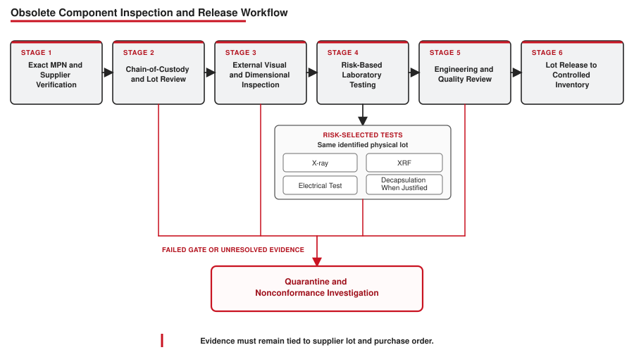
Begin with the original manufacturer and its authorized distribution network. Some manufacturers also identify authorized resellers for discontinued inventory. When required stock is available only through an independent obsolete electronic component supplier, increase the level of evidence, inspection and testing instead of treating the quotation as equivalent to factory-authorized supply.
Questions for Obsolete Electronic Component Suppliers
| Question | Useful evidence | Reason for concern |
|---|---|---|
| Who manufactured the parts and what is the exact MPN? | Full orderable code, clear package photos and manufacturer-consistent markings. | Generic descriptions, cropped markings or changing manufacturer claims. |
| Where did this lot originate? | Traceable chain of custody, original purchasing records or defensible ownership history. | "Factory direct" with no records or an undisclosed upstream source. |
| Is the quantity one homogeneous lot? | Date-code and lot-code breakdown, reel/tray labels and quantity by lot. | Mixed lots represented as one factory lot. |
| How was it stored and handled? | ESD controls, moisture-barrier condition, humidity indicator and storage records where applicable. | Loose devices, damaged tubes, resealed bags or unknown floor life. |
| What inspection and testing are included? | Named test methods, sample size, acceptance criteria, laboratory identity and unedited results tied to the lot. | "100% tested" without test limits, method or report. |
| What happens after a nonconformance? | Written return, quarantine, investigation and traceability process. | No return rights or pressure to accept before inspection. |
Pricing far below the rest of the market, an implausibly large quantity of a scarce date code, or immediate availability from many unrelated locations deserves investigation. None proves a counterfeit by itself; together they change the risk classification and required verification.
Use a Risk-Based Inspection and Test Plan
Counterfeit control starts with source selection and traceability. Testing is a second line of evidence. The plan should account for part type, source, intended use, lot value, safety criticality and the failures that inspection must detect.
| Layer | What it can reveal | What it cannot establish alone |
|---|---|---|
| Documentation review | Breaks in chain of custody, inconsistent quantities, dates or manufacturer records. | The physical identity and performance of every device. |
| External visual and dimensional inspection | Marking anomalies, resurfacing indicators, package damage, lead rework and dimensional mismatch. | Correct die, complete electrical performance or remaining life. |
| X-ray | Die presence, wire-bond pattern, gross internal construction differences and some package anomalies. | Firmware, detailed die identity or full electrical compliance. |
| XRF | Elemental composition useful for finish and material-composition checks. | Logic function, speed grade or authenticity by itself. |
| Electrical testing | Function and selected parametric limits under defined conditions. | Complete process pedigree or long-term reliability unless the plan addresses them. |
| Decapsulation / internal analysis | Die markings and internal construction for sampled devices. | Every unit in the lot; the tested samples are destroyed. |
Specify the sampling plan and acceptance criteria before the supplier ships. If destructive testing is required, agree on who selects the samples, how the tested lot remains controlled and what happens when any sample fails. Reports must reference the supplier lot, customer purchase order and inspected quantity so that results cannot be detached from the material they represent.
Handle Date Code and Storage as Engineering Variables
An old date code is not automatic proof of damage, and a recent date code is not proof of authenticity. Evaluate package condition, moisture sensitivity, dry-pack integrity, floor-life exposure, terminal finish, solderability and the manufacturer's storage guidance.
Do not bake components from a generic schedule. Excessive temperature or duration can damage packaging, oxidize terminals or deform carrier materials. The correct recovery process depends on package construction, moisture sensitivity level, exposure history and manufacturer guidance.
For a large lifetime buy, define controlled storage, periodic inventory inspection, traceable withdrawals and a method for monitoring solderability or other aging-sensitive attributes over the service period.
Information Needed for a Useful Obsolete-Part RFQ
A precise request reduces false matches among hard-to-find electronic parts. Include:
- complete manufacturer part number and preferred manufacturer;
- required quantity, target delivery and whether split delivery is acceptable;
- package, temperature grade, qualification and packing requirements;
- acceptable lot splits or date-code constraints, with the engineering reason for any restriction;
- required traceability and certificate documents;
- inspection, electrical test or third-party laboratory requirements;
- whether alternates may be proposed and which attributes are mandatory;
- destination, compliance requirements and any customer-controlled approval process.
For an active sourcing case, send the exact part number, quantity and quality requirements through the Aetrix RFQ form. If alternates are acceptable, state that explicitly; an unapproved substitute should never be silently quoted as the requested manufacturer part number.
Reduce the Next Obsolescence Event
Obsolescence management works best while the BOM is still healthy. IEC 62402 treats it as a lifecycle process rather than an emergency purchasing activity. The operational version is straightforward:
- monitor manufacturer lifecycle status and subscribe to PCN/PDN notices;
- retain exact orderable codes instead of shortened family names in the BOM;
- record approved alternates and the evidence supporting each approval;
- prefer components with suitable lifecycle commitments for long-life designs;
- identify single-source and high-redesign-impact items during design review;
- keep validation fixtures, firmware builds and test limits usable for alternate qualification;
- assign owners and deadlines when a lifecycle notice arrives;
- review service demand before production ends, not after field stock is exhausted.
The strongest plan leaves more than one controlled route open. A short bridge buy protects the schedule, qualification work restores sustainable supply, and documented traceability protects the material used before the alternate is ready.
Technical References
- IEC 62402:2019 - Obsolescence management
- Texas Instruments - Product lifecycle status definitions
- Texas Instruments - Product withdrawal and discontinuance process
- NXP - Product lifecycle definitions
- Analog Devices - Product life cycle and obsolescence information
- Texas Instruments - Anti-counterfeit sourcing guidance
- SAE AS6171/2 - External visual inspection techniques
- SAE AS6171/3 - X-ray fluorescence test methods
- Texas Instruments - SN75C185DW lifecycle and replacement information
- Texas Instruments - TPS54618QRTERQ1 lifecycle and replacement information
- Nexperia - 74HC00 orderable-code status and data sheet
- Texas Instruments - CD74HC00 data sheet and orderable status
Frequently Asked Questions
What does obsolete mean for an electronic component?
It means the manufacturer no longer produces the exact orderable part and does not accept normal new orders for it. Existing distributor or broker inventory may still be available.
Are EOL and NRND the same?
No. NRND means the manufacturer does not recommend the part for new designs, but existing orders may continue. EOL means discontinuance has begun, usually with defined last-order and last-shipment dates.
Is a pin-to-pin replacement automatically safe?
No. Pin alignment does not establish electrical limits, timing, startup behavior, firmware compatibility, thermal performance or qualification. These must be checked against the application.
When does a last-time buy make sense?
It is suitable when remaining demand can be estimated with defensible assumptions and the cost and storage risk are lower than immediate replacement or redesign. The calculation should include production, service, yield loss, existing usable inventory and confirmed open orders.
Can visual inspection prove that obsolete electronic parts are authentic?
No. It can identify anomalies and support a wider evidence set, but it cannot establish die identity, full electrical compliance or long-term reliability by itself.
What should be checked when evaluating obsolete component suppliers?
Check the source and chain of custody, lot structure, storage history, inspection and test plan, report traceability, nonconformance process and return terms. Apply more verification when manufacturer traceability is weaker.
Can a newer component with better specifications replace the old one?
Only after application-level review. Faster edges, different protection structures, lower current limits, changed startup states or revised firmware behavior can create failures even when headline specifications look better.
Can an obsolete component be replaced by the same function from another manufacturer?
Yes, when the exact cross-brand candidate passes package, pinout, guaranteed electrical, timing, environmental and application-level checks. A shared generic function or base number is not enough; the BOM, AVL and change record must identify the approved manufacturer and orderable code.
What information should an obsolete electronic parts RFQ include?
Provide the full manufacturer part number, quantity, delivery need, package and grade, packing, traceability, lot or date-code constraints, testing requirements and whether proposed alternates are permitted.


