
 My Inquiry
 My Account


SCR Silicon Controlled Rectifier Working Principle and Applications
Article Details
SCR, or silicon controlled rectifier, is a power semiconductor device widely used in industrial electronics and AC power control systems. SCRs are commonly found in motor drives, light dimmers, industrial rectifiers, heater controllers, and battery charging circuits.
Unlike standard diodes, SCRs provide controlled switching. Once triggered, they conduct current efficiently with low conduction loss. This characteristic allows SCRs to handle large currents while maintaining system stability, making them ideal for industrial and high-power applications.
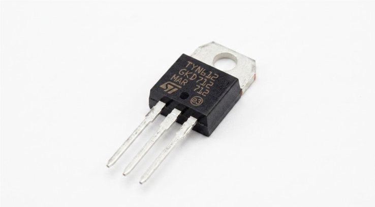
SCR Gate Triggering and Gate Drive Design
SCR conduction is initiated by applying a triggering pulse to the gate terminal. Correct gate current, pulse width, and timing are critical to reliable operation. Under-driving the gate may result in failed triggering, while excessive gate current can generate unnecessary heat.
In practical engineering, a SCR Gate Trigger Calculator helps estimate the optimal gate current and pulse duration based on device ratings and load requirements. This allows engineers to design triggering circuits for AC or DC SCRs with consistent performance and minimal thermal stress.
SCR Internal Structure
A silicon controlled rectifier contains four semiconductor layers (PNPN) and three junctions. This structure is often modeled as two interconnected transistors for analysis. Understanding the PNPN layers is essential for troubleshooting SCR boards in industrial drives, as many failures are associated with gate driver or junction degradation rather than the SCR die itself.
SCR Working Principle
Even when forward voltage is applied, an SCR remains non-conductive until a gate pulse is applied. After latching, the SCR continues to conduct until the anode current falls below the holding current or the AC waveform crosses zero. This latching behavior is particularly useful for AC phase control in industrial dimmers and motor drives, allowing precise power regulation.
SCR Symbol and Circuit Representation
The SCR symbol resembles a diode with an additional gate terminal. In circuit diagrams, engineers must accurately identify anode, cathode, and gate connections. SCR schematic symbols are critical when analyzing rectifier circuits, AC dimmers, and motor control boards. Visual recognition of these symbols helps during PCB troubleshooting and design verification.
SCR Circuits and Applications
Silicon controlled rectifier circuits are essential in power regulation. In AC dimmer circuits, the SCR firing angle determines the average power delivered. In motor control circuits, phase-angle control allows smooth speed adjustment without complex switching topologies.
Common SCR applications include:
- AC light dimmers
- DC and AC motor controllers
- Battery chargers
- Industrial heater controllers
- Controlled rectifiers
- Soft starter circuits
Power Dissipation and Thermal Management
SCR devices dissipate power as heat during conduction. Junction temperature directly affects reliability. Engineers often calculate the expected thermal load to determine proper heatsink size and airflow requirements. Improper thermal management can cause premature SCR failure, even if electrical ratings are not exceeded.
To support engineering design, a Power Dissipation & Thermal Calculator can be used to estimate junction temperature and required heatsink characteristics based on conduction current, voltage drop, and duty cycle. Using this tool ensures SCR modules operate within safe thermal limits.
SCR Triggering Methods
Gate triggering is the standard method, but SCRs can also inadvertently fire due to:
- Excessive dv/dt
- High forward voltage
- Thermal overstress
Industrial engineers typically use RC snubbers, gate resistors, and optimized PCB layouts to prevent false triggering in high-power SCR installations.
SCR vs Diodes
While both SCRs and diodes allow current to flow in one direction, only SCRs provide controllable conduction via the gate terminal and latch behavior. This makes SCRs suitable for applications where controlled power delivery is required, unlike passive rectification.
| Feature | SCR | Diode |
|---|---|---|
| Gate Control | Yes | No |
| Latching Behavior | Yes | No |
| Controlled Switching | Yes | No |
| Power Handling | High | Moderate |
Thyristor Family and SCR
SCR devices belong to the thyristor family, alongside TRIACs, DIACs, GTOs, and IGCTs. Their simplicity and high-current capability make SCRs particularly useful in industrial AC control applications.
SCR Testing and Troubleshooting
Testing an SCR typically involves verifying anode-to-cathode resistance, gate sensitivity, and ensuring no permanent short exists. Engineers often examine the gate drive network and snubber circuits first. Common SCR failures include:
- Open junctions
- Permanent shorts
- Gate triggering failure
- Excess leakage under voltage stress
Field experience shows that many failures are caused by heat cycling around the gate drive rather than the SCR die itself.
SCR Motor Control
SCRs are widely used in motor drives. In DC systems, controlled rectifier circuits adjust the average voltage to the motor, providing smooth acceleration. In industrial AC systems, phase-angle control regulates motor speed and torque.
Older industrial DC drives often mount SCR modules on large aluminum heat sinks to dissipate heat generated during long-duration operation.
SCR Light Dimmer Circuits
SCR-based dimmers control power by delaying conduction during each AC half-cycle. Adjusting the firing angle changes the average voltage applied to the lamp. Engineers designing dimmers must also account for thermal stress and EMI suppression in practical circuits.
SCR Advantages and Limitations
| Advantage | Description |
|---|---|
| High Current Capability | Suitable for industrial and high-power applications |
| Controlled Switching | Gate-triggered conduction with latching behavior |
| Efficiency | Low conduction loss in high-current paths |
| Reliability | Proven performance in industrial environments |
| Limitation | Description |
|---|---|
| Turn-off Control | Cannot turn off via gate; requires current interruption |
| Switching Speed | Lower than MOSFETs or IGBTs, unsuitable for high-frequency switching |
| AC Commutation | Requires proper circuit design for AC systems |
SCR in Modern Industrial Electronics
Despite the rise of MOSFET and IGBT devices, SCRs remain important for high-current, low-frequency AC control applications. Large rectifiers, soft starters, and heater controllers continue to use SCRs because of their robust conduction and proven reliability. Thermal management with heatsinks and snubbers is essential in long-term operation, especially under high duty cycles.


