What Is a Decoder? Digital Logic, Decoder ICs and Electronics Applications Explained
Article Details
A decoder is an electronic circuit or integrated circuit that converts a coded input into a specific output state. In digital logic, a decoder usually receives a binary input code and activates one output line that corresponds to that input combination. This makes decoders useful in address selection, memory control, display driving, peripheral selection, and digital control circuits.
The word decoder is also used in software, vehicle identification, media processing, and data conversion. For example, searches for VIN decoder, Base64 decode, URL decode, or JWT decode refer to different types of decoding. In electronics, however, a decoder usually means a logic circuit, decoder IC, display decoder, address decoder, or signal-processing device that interprets encoded information and produces a useful output.
This guide focuses on decoders in electronic circuits, including binary decoders, 2-to-4 decoders, 3-to-8 decoder ICs, BCD to 7-segment decoders, address decoding, encoder vs decoder differences, and practical selection points for decoder ICs.
What Is a Decoder in Electronics?
In electronics, a decoder is a combinational logic circuit that maps an input code to one or more output signals. A common digital decoder has n input lines and up to 2n output lines. For each valid input combination, one output line is selected.
For example, a 2-to-4 decoder has two binary inputs and four output lines. A 3-to-8 decoder has three binary inputs and eight output lines. A 4-to-16 decoder has four binary inputs and sixteen output lines. This structure is useful when a system needs to select one device, one memory block, one display digit, or one control path from several possible outputs.
A decoder is often described as the reverse of an encoder. An encoder takes several input lines and converts the active input into a coded output. A decoder takes a coded input and converts it back into a selected output line. (All About Circuits, Decoder)
How a Digital Logic Decoder Works
A digital logic decoder uses input bits to determine which output should become active. In a simple active-high decoder, the selected output becomes logic high while the other outputs stay low. In an active-low decoder, the selected output becomes logic low while the other outputs remain high.
Many practical decoder ICs also include enable pins. The enable input allows the decoder to be turned on or off by another logic signal. This is useful when several decoders share a bus, when a processor needs to select only one peripheral, or when a larger decoder function is built from smaller decoder ICs.
| A1 | A0 | Selected Output | 2-to-4 Decoder Meaning |
|---|---|---|---|
| 0 | 0 | Y0 | Input code 00 selects output 0. |
| 0 | 1 | Y1 | Input code 01 selects output 1. |
| 1 | 0 | Y2 | Input code 10 selects output 2. |
| 1 | 1 | Y3 | Input code 11 selects output 3. |
The same principle scales to larger devices. A 3-to-8 decoder uses three inputs to select one of eight outputs, and a 4-to-16 decoder uses four inputs to select one of sixteen outputs.
For a visual explanation of decoder basics, decoder applications, 3-to-8 decoder logic, BCD decoding, and larger decoder expansion, the following video gives a useful electronics-focused overview before moving into decoder IC selection and circuit applications.
Common Types of Decoder ICs
Decoder ICs are available in several logic families and output configurations. Some are simple binary line decoders, while others are designed for decimal output, 7-segment display driving, demultiplexing, or address decoding.
| Decoder Type | Function | Typical Use |
|---|---|---|
| 2-to-4 decoder | Converts two binary inputs into one of four outputs | Small logic selection, simple control circuits |
| 3-to-8 decoder | Converts three binary inputs into one of eight outputs | Address decoding, peripheral selection, demultiplexing |
| 4-to-16 decoder | Converts four binary inputs into one of sixteen outputs | Memory selection, larger control systems |
| BCD to decimal decoder | Converts a binary-coded decimal input into decimal output lines | Numeric selection, counter output decoding |
| BCD to 7-segment decoder | Converts BCD input into segment control outputs | LED display modules, counters, meters, panels |
| Address decoder | Selects memory or I/O devices based on address lines | Microcontroller, processor, SRAM, Flash, I/O systems |
| Audio or video decoder IC | Converts encoded media data into usable audio or video signals | Consumer electronics, display systems, media equipment |
| Communication decoder | Interprets protocol, serial data, or encoded signal formats | CAN, LIN, UART debugging, industrial communication |
A widely used example is the 74HC138, a 3-to-8 line decoder/demultiplexer. Devices in this class decode three binary address inputs into eight mutually exclusive outputs, and enable inputs can be used for expansion or demultiplexer operation. (Nexperia, 74HC138; 74HCT138)
Decoder vs Encoder
Encoder and decoder circuits are related but opposite in direction. An encoder reduces multiple input lines into a smaller coded output. A decoder expands a coded input into selected output lines. In a control system, an encoder may create a compact binary representation, while a decoder may later interpret that code to drive a device, select an address, or activate an output.
| Function | Encoder | Decoder |
|---|---|---|
| Signal direction | Many inputs to fewer coded outputs | Coded inputs to many possible outputs |
| Example | 8-to-3 priority encoder | 3-to-8 decoder |
| Main purpose | Generate a code | Interpret a code |
| Common use | Keyboards, priority logic, interrupt systems | Memory selection, display driving, control outputs |
In practice, encoders and decoders often appear in the same system. A keypad may use encoding to reduce wiring. A display or memory system may use decoding to select the correct output, device, or address range.
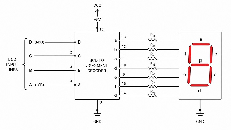
BCD to 7-Segment Decoder
A BCD to 7-segment decoder converts a binary-coded decimal input into segment outputs for a numeric display. A 7-segment display has seven LED segments, usually named a through g. By turning different segments on or off, the display can show digits from 0 to 9.
This type of decoder is common in counters, meters, clocks, panel instruments, simple test equipment, and industrial display modules. Parts such as the CD4511 are often associated with BCD to 7-segment display decoding in older and simple digital display designs.
| Design Point | Why It Matters |
|---|---|
| Common anode or common cathode display | The decoder output type must match the LED display structure. |
| Output current | The decoder may not be able to directly drive all LED segments without drivers. |
| Current-limiting resistors | LED segments usually need current control to prevent damage. |
| Blanking and latch functions | Some display decoder ICs include extra control pins for display behavior. |
| Supply voltage | The decoder, display, and upstream logic must use compatible voltage levels. |
A 7-segment decoder is convenient because it removes the need for a controller to manually generate every segment pattern. The controller or counter only provides the BCD input, and the decoder handles the display segment outputs.
Address Decoding in Microcontroller and Memory Systems
Address decoding is one of the most important uses of decoder circuits in processor-based systems. When a microcontroller, microprocessor, or external bus system accesses memory or peripherals, address lines define which device or address range should respond.
An address decoder monitors the address lines and activates a chip select, output enable, or peripheral enable signal when the address matches a target range. This can be done with discrete logic gates, a decoder IC such as the 74HC138, a larger decoder such as the 74HC154, or programmable logic such as a CPLD, FPGA, or MCU internal address-mapping logic.
| Address Decoding Use Case | Example | Design Concern |
|---|---|---|
| Memory chip selection | Selecting SRAM, Flash, EEPROM, or ROM devices | Address range, chip select timing, bus loading |
| I/O mapped peripheral selection | Selecting external UART, GPIO, display, or control device | Address overlap, enable polarity, propagation delay |
| Bank selection | Selecting one memory bank from several banks | Decoder expansion, logic timing, unused states |
| Control signal generation | Generating mutually exclusive control lines | Glitches, enable timing, fanout, active-low outputs |
Address decoding problems can be difficult to debug because the circuit may appear to work at low speed but fail when timing margins become smaller. Propagation delay, bus capacitance, enable timing, and address-line stability should be reviewed carefully in faster systems.
Decoder IC Selection Parameters
Choosing a decoder IC is not only a matter of input and output count. The logic family, supply voltage, output polarity, enable configuration, propagation delay, package, and temperature rating can all affect circuit behavior.
| Parameter | Selection Question |
|---|---|
| Logic family | Is the circuit using TTL, CMOS, 74HC, 74HCT, 74LVC, or another logic family? |
| Supply voltage | Does the decoder support the system logic voltage, such as 3.3V or 5V? |
| Input threshold | Are the input high and low thresholds compatible with the driving logic? |
| Output polarity | Are the outputs active-high or active-low? |
| Enable pins | How many enable inputs are needed, and what polarity do they use? |
| Propagation delay | Is the decoder fast enough for the address, control, or timing path? |
| Output drive current | Can the output drive the connected logic, LED driver, or transistor input? |
| Package | Is the package suitable for PCB layout, assembly, repair, and availability? |
| Temperature range | Does the part meet commercial, industrial, automotive, or extended temperature requirements? |
TI lists the CD74HC138 as a high-speed CMOS 3-to-8 line decoder/demultiplexer, with device documentation covering decoder/demultiplexer variants, package options, operating temperature range, and ordering information. (Texas Instruments, CD74HC138)
Decoder Applications in Electronics
Decoders are used wherever a compact code must be converted into a physical output, selected line, display state, or device enable signal. They appear in simple logic circuits as well as larger embedded, industrial, and computing systems.
| Application | How the Decoder Is Used |
|---|---|
| Memory address selection | Selects one memory device or address block from several options. |
| Microcontroller peripheral control | Generates chip select or enable signals for external devices. |
| LED display driving | Converts BCD or binary input into display segment or digit control. |
| Keypad and control panels | Helps scan, select, or interpret rows, columns, and control lines. |
| Relay or driver selection | Activates one output driver from a binary command. |
| Test equipment | Selects channels, ranges, input paths, or display states. |
| Communication systems | Interprets encoded data, protocol fields, or channel selections. |
| Audio and video electronics | Decodes compressed or formatted data into usable signal outputs. |
A decoder is often a small part of the overall system, but it can control which part of the system is active. For that reason, a wrong decoder output polarity, incorrect enable state, or slow propagation delay can affect the entire circuit.
Common Mistakes When Using Decoder ICs
Decoder circuits are simple in principle, but practical implementation errors are common. Many problems come from assuming all decoder outputs behave the same way, or from ignoring enable pins and logic-level compatibility.
- Ignoring active-low outputs on decoder ICs such as many 3-to-8 decoder/demultiplexer devices.
- Leaving enable pins floating or tying them to the wrong logic level.
- Using a 5V CMOS output to drive a lower-voltage device without checking input tolerance.
- Mixing 74HC and 74HCT logic without checking input thresholds.
- Driving LEDs directly without checking output current and resistor requirements.
- Allowing unused inputs to float instead of tying them to defined logic states.
- Creating overlapping address ranges in memory or peripheral decoding.
- Ignoring propagation delay in timing-sensitive address or control paths.
- Assuming similar part numbers are pin-compatible without checking the datasheet.
- Choosing a package that is difficult to source or unsuitable for production assembly.
Quick Reference: Decoder ICs and Related Logic Parts
| Part or Device Type | Typical Function | Common Design Use |
|---|---|---|
| 74HC138 | 3-to-8 line decoder/demultiplexer | Address decoding, chip select generation, demultiplexing |
| 74HCT138 | TTL-compatible 3-to-8 line decoder/demultiplexer | 5V logic systems with TTL-level input compatibility |
| 74HC238 | 3-to-8 line decoder with non-inverting outputs | Control logic where active-high outputs are preferred |
| 74HC154 | 4-to-16 line decoder/demultiplexer | Larger address selection or control-line expansion |
| CD4511 | BCD to 7-segment latch/decoder/driver | Numeric LED display driving |
| 74HC42 | BCD to decimal decoder | Decimal output selection from BCD input |
A decoder converts an input code into a selected output, making it one of the basic building blocks of digital logic and electronic control systems. In simple circuits, it may select one LED, relay, display digit, or logic path. In larger systems, it may generate memory chip selects, peripheral enables, display segment outputs, or address-dependent control signals.
For reliable decoder selection, check the number of inputs and outputs, active-high or active-low behavior, enable pins, logic family, supply voltage, propagation delay, output drive, package, and temperature range. A decoder IC is usually simple to use, but its output polarity and timing can determine whether the rest of the circuit works correctly.