
 My Inquiry
 My Account


Infineon Technologies CY96F348HSCPQC-GSE2
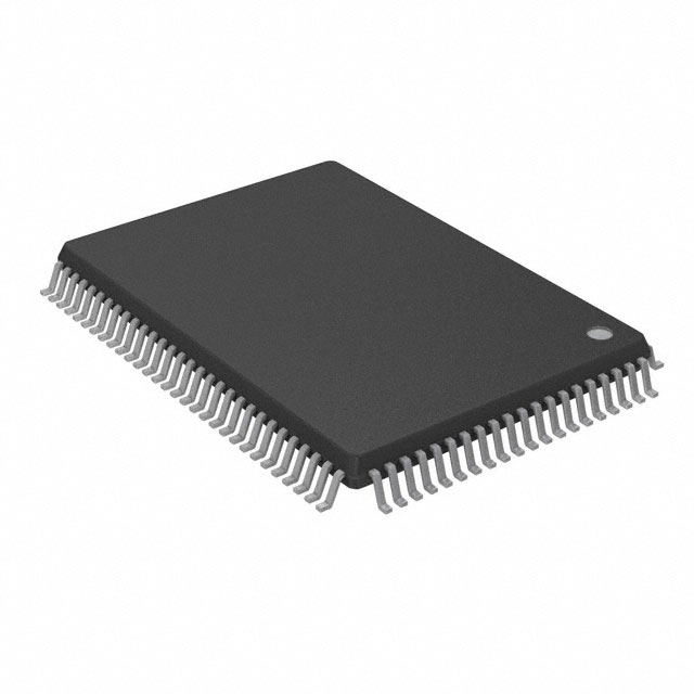
- Part No.:
- CY96F348HSCPQC-GSE2
- Manufacturer:
- Infineon Technologies
- Category:
- Microcontrollers
- Package:
- 100-BQFP
- Datasheet:
-
 CY96F348HSCPQC-GSE2.pdf
- Description:
- IC MCU 16BIT 576KB FLASH 100QFP
- Quantity:
- Payment:

- Shipping:

Inventory:1,229
Please send an inquiry. Send us your inquiry, and we will respond immediately.
Product details
Overview
CY96F348HSCPQC-GSE2 from Infineon Technologies (formerly Cypress) is a 16-bit F2MC-16FX microcontroller with dual CAN interfaces, 576 KB on-chip Flash (544 KB Flash A + 32 KB Flash B), 24 KB RAM, and 100-pin LQFP package. It operates at up to 56 MHz via internal PLL (17.8 ns instruction cycle), supports 24-channel 10-bit SAR ADC, dual I²C, seven USARTs (including LIN), and real-time clock with calibration. Used in automotive body control modules requiring deterministic CAN communication and mixed-signal processing.
For engineers reviewing the CY96F348HSCPQC-GSE2 datasheet, CY96F348HSCPQC-GSE2 pinout, CY96F348HSCPQC-GSE2 application, or CY96F348HSCPQC-GSE2 equivalent, key selection criteria include dual-CAN channel count, Flash memory partitioning (A/B), 24-channel ADC resolution and trigger sources, programmable pulse generator count (16 channels), and dual-clock domain support for independent CPU/peripheral timing.
Technical Context
The CY96F348HSCPQC-GSE2 implements the F2MC-16FX CPU core with RISC-like pipelined execution, 23 addressing modes, and native 16×16 signed multiply/32÷16 divide instructions. Its clock system integrates a programmable PLL (×1–×25), dual oscillators (main 3–16 MHz crystal + sub 32–100 kHz quartz), and on-chip RC oscillator for fail-safe startup.
Peripheral architecture features two independent CAN 2.0A/B controllers (ISO16845 certified, up to 1 Mbit/s), seven full-duplex USARTs with LIN master/slave capability, and a flexible DMA controller with 6 channels assigned across ADC, CAN, USART, and I²C. The 24-channel ADC supports software/external/reload-timer triggering and dual reference voltage switching (AVRH/AVRL or AVRH2).
Key Specifications
| Parameter | Value and Actual Design Meaning |
|---|---|
| CPU Core | F2MC-16FX 16-bit RISC-like pipeline; enables migration from 16LX software with same instruction set. |
| Max Clock Speed | 56 MHz CPU frequency via PLL; achieves 17.8 ns minimum instruction cycle time. |
| Memory | 576 KB Flash (544 KB Flash A + 32 KB Flash B), 24 KB RAM; supports sector erase (10k cycles) and 20-year data retention. |
| CAN Interfaces | 2 × ISO16845-certified CAN 2.0A/B controllers; each with 32 message objects, FIFO mode, and loop-back self-test. |
| ADC | 24-channel 10-bit SAR ADC; supports single/continuous/stop conversion modes and external trigger from reload timer or GPIO. |
| Package | 100-pin LQFP (14 mm × 14 mm, 0.5 mm pitch); RoHS-compliant, industrial temperature range (−40°C to +85°C). |
| I/O & Peripherals | 82 GPIO pins; 7 USARTs (SCI/LIN), 2 I²C (400 kbps), 4 × 16-bit reload timers, 2 × 16-bit free-running timers, 16 PPG channels. |
Pinout & Package
Package: 100-pin LQFP (14 mm × 14 mm, 0.5 mm pitch), lead-free and RoHS compliant. Pin functions validated per Cypress/Infineon datasheet 002-04579 Rev. *C, pages 7–11.
| Pin/Terminal | Circuit Role | Design Meaning |
|---|---|---|
| VCC / VSS | Power supply / Ground | Dedicated analog/digital power pins; AVCC/AVSS isolated for clean ADC reference. |
| X0 / X1 | Main crystal oscillator input/output | Supports 3–16 MHz crystal or ceramic resonator; determines base clock for PLL and peripherals. |
| MD0–MD2 | Mode select inputs | Configure boot mode (ROM/Flash), reset behavior, and low-voltage detection settings at power-on. |
| RSTX | Active-low reset input | Asynchronous external reset; also accepts watchdog timeout or low-voltage detector assertion. |
| CAN0_TX / CAN0_RX | CAN Channel 0 differential signal interface | Direct connection to external CAN transceiver; supports bit rates up to 1 Mbit/s. |
| CAN1_TX / CAN1_RX | CAN Channel 1 differential signal interface | Independent second CAN bus; enables multi-bus automotive networks (e.g., powertrain + body). |
| AN0–AN23 | Analog input channels | 24 dedicated ADC inputs; support programmable Schmitt-trigger or TTL input levels on shared pins. |
| TX0–TX6 / RX0–RX6 | USART transmit/receive lines | Seven independent full-duplex SCI/LIN interfaces; SINx pins support wake-up interrupt on falling edge. |
Key Features
| Feature | Design Value |
|---|---|
| Dual independent CAN 2.0A/B controllers | Each with 32 message objects, maskable interrupts, and programmable FIFO; eliminates need for external CAN protocol handlers. |
| Flash memory partitioning (Flash A + Flash B) | Enables safe over-the-air (OTA) firmware updates with rollback capability using separate 544 KB and 32 KB banks. |
| 24-channel 10-bit SAR ADC with dual reference switching | Allows simultaneous measurement of sensors with different full-scale ranges (e.g., 3.3 V and 5 V rails) without external muxing. |
| 16-channel programmable pulse generator (PPG) | Generates precise PWM waveforms with independent cycle/duty registers and internal prescaler (1/4–1/64); replaces discrete timer-PWM ICs. |
| Dual-clock domain operation | CPU and peripheral clocks independently selectable from main oscillator, sub-oscillator, or RC source; reduces EMI and optimizes power per subsystem. |
Applications
| Body Control Module (BCM) | Electric Power Steering (EPS) Sensor Interface |
|---|---|
|
Use Scenario: Centralized vehicle body electronics managing door locks, lighting, wipers, and HVAC via CAN network. IC Role / Device Role / Timing Role: Main MCU executing real-time control tasks, coordinating multiple CAN nodes, and sampling analog sensor inputs (e.g., ambient light, temperature). Use Value: Dual CAN controllers enable concurrent communication on comfort and chassis buses; 24-channel ADC acquires signals from 12+ analog sensors without external multiplexers. |
Use Scenario: Signal conditioning and preprocessing for torque, angle, and motor current sensors in EPS systems. IC Role / Device Role / Timing Role: High-precision analog front-end with synchronized ADC sampling and CAN message framing for closed-loop motor control. Use Value: 10-bit ADC with reload-timer triggering ensures deterministic sampling intervals (<1 µs jitter); CAN TX/RX hardware buffering prevents message loss during high-priority ISR execution. |
| Commercial Vehicle Telematics Gateway | Industrial CAN-based PLC I/O Controller |
|
Use Scenario: Aggregating data from engine, transmission, and trailer CAN buses for remote diagnostics and fleet management. IC Role / Device Role / Timing Role: Multi-CAN gateway with protocol translation, message filtering, and secure OTA update handling via Flash B bank. Use Value: Flash B (32 KB) stores verified firmware images for atomic swap; dual CAN ports isolate primary and secondary bus traffic to prevent cross-contamination. |
Use Scenario: Modular I/O controller in factory automation, acquiring digital/analog inputs and driving relay/valve outputs over CANopen network. IC Role / Device Role / Timing Role: Deterministic real-time controller with programmable pulse generators for stepper motor control and alarm comparator for overvoltage monitoring. Use Value: 16 PPG channels generate synchronized step/direction signals for up to 8 axes; alarm comparator triggers immediate CAN alert on input rail deviation (>±5% threshold). |
Equivalent & Alternatives
The following parts are listed as comparable options for similar 16-bit automotive microcontroller applications.
| Alternative Part | Technical Difference | Application Difference | Selection Advice |
|---|---|---|---|
| SPC560P50L5 | 32-bit Power Architecture core, 512 KB Flash, single CAN FD port, no integrated LIN | Targets higher-performance powertrain control; lacks native LIN slave support and dual-CAN redundancy | Select when CAN FD bandwidth >1 Mbit/s is required and LIN is handled externally |
| RL78/F14 | 16-bit RL78 core, 512 KB Flash, 2 CAN 2.0B ports, 26-channel 10-bit ADC, no Flash B partitioning | Offers larger ADC channel count but lacks dedicated Flash B for atomic OTA updates | Select for cost-sensitive body electronics where dual-bank firmware update is not mandatory |
Compared with SPC560P50L5 and RL78/F14, CY96F348HSCPQC-GSE2 uniquely combines dual-CAN 2.0A/B, Flash A/B partitioning for robust OTA, and LIN-capable USARTs in a single 100-pin LQFP - enabling compact, functionally safe body domain controllers without external protocol bridges.
Availability
CY96F348HSCPQC-GSE2 is available at Aetrix Electronics and suitable for automotive body control modules, electric power steering sensor interfaces, commercial vehicle telematics gateways, and industrial CAN-based PLC I/O controllers requiring stable component supply and long-term lifecycle support.
Supply support for CY96F348HSCPQC-GSE2 includes scheduled delivery planning, volume procurement assistance, BOM continuity management, traceable sourcing, and lifecycle availability coordination for OEM customers, industrial embedded developers, connected-device designers, and electronics production programs.
Manufacturer
Infineon Technologies is a global semiconductor leader headquartered in Munich, Germany, specializing in power management, automotive MCUs, and security solutions with vertical integration from silicon to system-level software.
CY96F348HSCPQC-GSE2 belongs to the F2MC-16FX microcontroller family, designed specifically for cost-optimized, functional-safety-aware automotive body electronics and industrial CAN networks requiring deterministic real-time performance and field-upgradable firmware.
FAQ
What is the maximum operating frequency and corresponding instruction cycle time of the CY96F348HSCPQC-GSE2?
The CY96F348HSCPQC-GSE2 achieves a maximum CPU clock frequency of 56 MHz using its internal PLL multiplier. This yields a minimum instruction cycle time of 17.8 ns, confirmed in the datasheet's AC characteristics table (page 68). The core maintains this performance across the full industrial temperature range (−40°C to +85°C) under specified VCC conditions.
Does the CY96F348HSCPQC-GSE2 support LIN communication, and if so, how many channels?
Yes, the CY96F348HSCPQC-GSE2 supports LIN communication via seven full-duplex USART channels (TX0–TX6 / RX0–RX6), each configurable as LIN master or slave per the SCI/LIN mode register settings. LIN functionality is implemented in hardware with automatic header detection, checksum generation, and sync field handling - no CPU overhead required for basic frame transmission.
How is Flash memory organized, and what is the endurance specification?
CY96F348HSCPQC-GSE2 contains 576 KB of on-chip Flash memory divided into 544 KB Flash A and 32 KB Flash B. Each sector supports 10,000 erase/write cycles, with guaranteed data retention of 20 years at +85°C. Sector protection and Flash security features prevent unauthorized read-out or modification of critical firmware sections.
What are the supported clock sources for the real-time clock (RTC) module?
The RTC module can be clocked from three independent sources: the 32–100 kHz sub-oscillator (quartz), the main oscillator (via programmable divider), or the on-chip 100 kHz/2 MHz RC oscillator. Clock calibration logic compensates for quartz drift, and registers for seconds, minutes, hours, and days are directly readable/writable via memory-mapped I/O at address 0xFFE000–0xFFE00F.
CY96F348HSCPQC-GSE2 Specifications
- Product attributes
- Attribute value
- Manufacturer:
- Infineon Technologies
- Package/Case:
- 100-BQFP
- Series:
- F²MC-16FX CY96340
- Packaging:
- Tray
- Product Status:
- Obsolete
- Programmable:
- Not Verified
- Core Processor:
- F²MC-16FX
- Core Size:
- 16-Bit
- Speed:
- 56MHz
- Connectivity:
- CANbus, EBI/EMI, I2C, LINbus, SCI, UART/USART
- Peripherals:
- DMA, LVD, LVR, POR, PWM, WDT
- Number of I/O:
- 82
- Program Memory Size:
- 576KB (576K x 8)
- Program Memory Type:
- FLASH
- EEPROM Size:
- -
- RAM Size:
- 24K x 8
- Voltage - Supply (Vcc/Vdd):
- 3V ~ 5.5V
- Data Converters:
- A/D 24x10b SAR
- Oscillator Type:
- Internal
- Operating Temperature:
- -40°C ~ 105°C (TA)
- Grade:
- -
- Qualification:
- -
- Mounting Type:
- Surface Mount
- Supplier Device Package:
CY96F348HSCPQC-GSE2 FAQ
1.How can I place an order for CY96F348HSCPQC-GSE2 through Aetrix?
Please submit a Request for Quotation (RFQ) for CY96F348HSCPQC-GSE2 on Aetrix. Our sales agent will provide a competitive quotation and guide you through the order confirmation once you accept the terms.
2.Are the price and stock information for CY96F348HSCPQC-GSE2 reliable?
The price and inventory of CY96F348HSCPQC-GSE2 are updated periodically and may fluctuate due to market conditions. Stock and pricing data are typically refreshed every 24 hours. Quotation validity for CY96F348HSCPQC-GSE2 is usually 5 days.
3.What payment methods are accepted for CY96F348HSCPQC-GSE2?
We accept Wire Transfer, PayPal, Credit Card, Western Union, MoneyGram, and Escrow for CY96F348HSCPQC-GSE2 transactions.
Note: Certain payment methods may incur a processing fee.
4.How is shipping managed for CY96F348HSCPQC-GSE2?
CY96F348HSCPQC-GSE2 orders can be shipped via leading logistics carriers, including DHL, UPS, FedEx, TNT, or Registered Mail.
Once your CY96F348HSCPQC-GSE2 order is processed, you will receive an email with the shipment details and tracking number.
Note: Tracking information may take up to 24 hours to appear. Express delivery typically takes 3–5 business days.
5.How can I obtain technical support or documentation for CY96F348HSCPQC-GSE2?
For technical support, including CY96F348HSCPQC-GSE2 datasheets, pinout diagrams, or application guidance, please contact our engineering support team. They can provide detailed documentation and assistance for your CY96F348HSCPQC-GSE2 requirements.
6.How does Aetrix verify that CY96F348HSCPQC-GSE2 is sourced from the original manufacturer or authorized distributors?
All CY96F348HSCPQC-GSE2 products on Aetrix are procured from qualified distributors and authorized channels. Our dedicated quality assurance team conducts strict verification, including traceability checks and, if necessary, third-party testing. This ensures that CY96F348HSCPQC-GSE2 meets industry standards.
7.What is the process for return or replacement of CY96F348HSCPQC-GSE2?
All CY96F348HSCPQC-GSE2 units undergo pre-shipment inspection (PSI). If there is an issue with CY96F348HSCPQC-GSE2, returns or replacements are accepted under the following conditions:
1.Quantity discrepancies, incorrect items, or visible external defects (such as breakage or corrosion), acknowledged by Aetrix.
2.The issue is reported within 90 days of delivery.
3.The CY96F348HSCPQC-GSE2 part is unused and in its original packaging.
Return procedure for CY96F348HSCPQC-GSE2:
1.Submit a request within 90 days.
2.Obtain a Return Material Authorization (RMA) from Aetrix.
CY96F348HSCPQC-GSE2 Tags

-
ATTINY4-TSHR
Microchip Technology
-
ATTINY10-TSHR
Microchip Technology
-
ATTINY10-TS8R
Microchip Technology

-
ATTINY202-SSNR
Microchip Technology
-
ATTINY202-SSFR
Microchip Technology
-
ATTINY402-SSNR
Microchip Technology

-
PIC16F15213T-I/MF
Microchip Technology
-
PIC16F15213-E/MF
Microchip Technology

-
PIC10F200T-I/OT
Microchip Technology
-
ATTINY412-SSNR
Microchip Technology
-
PIC10F202T-I/OT
Microchip Technology

-
ATTINY404-SSNR
Microchip Technology
Tech Hub

18650 battery guide covering lithium-ion cell basics, 3.6V/3.7V voltage, 4.2V charging, mAh and Wh capacity, protected cells, chargers, BMS, series-parallel packs, holders, welding and sourcing checks.…

Hall effect sensor guide covering working principle, linear and digital sensors, Arduino circuits, current sensing, speed detection, automotive applications, A3144 examples, signal filtering and datash…

Product Change Notification guide for electronic components, covering PCN meaning, PCN vs PDN/EOL, common change types, risk levels, form-fit-function review, engineering validation, BOM control, LTB/L…

A practical guide to blend door actuators, covering HVAC function, symptoms, location, AC and heater issues, reset and calibration, replacement cost, electrical diagnosis, compatibility checks, and rep…

Engineering guide to Raspberry Pi alternatives, covering chip-level differences, Orange Pi, ROCK, Jetson, Banana Pi, NanoPi, Compute Module, Pico, GPIO, camera, HAT compatibility, and replacement risks…

Engineering guide to dynamic load response testing for high-current buck converters, covering load step setup, slew rate, Vcore undershoot, overshoot, recovery time, probe location, output capacitors a…

Engineering guide to output capacitor selection for ASIC Vcore rails, covering bulk capacitors, polymer capacitors, MLCC decoupling, DC bias, ESR, ESL, placement, transient response and substitution ri…

Engineering guide to high-current ASIC Vcore rails, covering 12-phase buck architecture, PMBus control, dynamic load testing, output capacitor networks, smart power stage selection, thermal design and …

Voltage regulator guide covering linear, LDO, 7805, Zener, adjustable, buck, VRM and alternator regulators, with design checks, testing methods, troubleshooting and datasheet-based selection.

Amplifier guide covering voltage, current and power amplification, gain, feedback, amplifier classes, audio and RF applications, op-amp circuits, transimpedance amplifiers, datasheet selection and trou…


