
 My Inquiry
 My Account


Infineon Technologies CY9AFA41NBPQC-G-JNE2
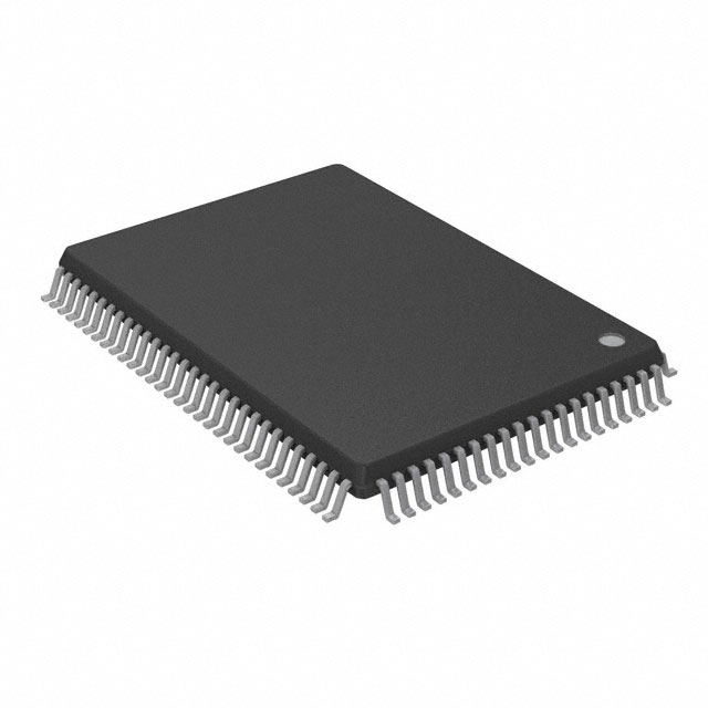
- Part No.:
- CY9AFA41NBPQC-G-JNE2
- Manufacturer:
- Infineon Technologies
- Category:
- Microcontrollers
- Package:
- 100-BQFP
- Datasheet:
-
 CY9AFA41NBPQC-G-JNE2.pdf
- Description:
- IC MCU 32BIT 96KB FLASH 100PQFP
- Quantity:
- Payment:

- Shipping:

Inventory:1,590
Please send an inquiry. Send us your inquiry, and we will respond immediately.
Product details
Overview
CY9AFA41NBPQC-G-JNE2 from Infineon Technologies (formerly Cypress) is a 32-bit ARM® Cortex®-M3 microcontroller with dual-bank flash (240 KB + 16 KB), 32 KB on-chip SRAM (16 KB SRAM0 + 16 KB SRAM1), and integrated LCD controller supporting up to 40×8 segment-combination drive. It operates at up to 40 MHz, supports six low-power modes including Deep Standby RTC, and targets embedded control in industrial HMI and appliance panels.
For engineers reviewing the CY9AFA41NBPQC-G-JNE2 datasheet, CY9AFA41NBPQC-G-JNE2 pinout, CY9AFA41NBPQC-G-JNE2 application, or CY9AFA41NBPQC-G-JNE2 equivalent, key selection criteria include dual-operation flash architecture, 24-channel 12-bit ADC with 2.0 μs conversion time, hardware flow control on UART ch.4, HDMI-CEC transceiver support, and 100-pin LQFP package with 5 V-tolerant I/O capability.
Technical Context
This MCU implements the ARM Cortex-M3 r2p1 core with NVIC supporting 48 peripheral interrupts and 16 priority levels, plus a 24-bit SysTick timer for RTOS integration. Its memory subsystem features independent I-code/D-code and system buses enabling concurrent CPU and DMA access to SRAM0 and SRAM1.
The peripheral set includes an 8-channel DMA controller with 32-bit addressing, dual 12-bit ADC units with FIFO-based scanning and priority conversion, and a programmable LCD controller with internal bias resistors and blinking function - all operating within 1.65–3.6 V supply range (2.2–3.6 V when LCDC active).
Key Specifications
| Parameter | Value and Actual Design Meaning |
|---|---|
| CPU Core | ARM Cortex-M3 r2p1, up to 40 MHz - enables deterministic real-time execution with Thumb-2 instruction set and hardware divide. |
| Flash Memory | 256 KB dual-bank (240 KB upper + 16 KB lower), 0-wait-state read - supports background erase/write for firmware updates without halting execution. |
| SRAM | 32 KB total: 16 KB SRAM0 (I/D bus), 16 KB SRAM1 (system bus) - enables parallel code/data access and DMA offload. |
| ADC | 2 × 12-bit SAR, 24 channels, 2.0 μs conversion @ 2.7–3.6 V - meets fast-sampling requirements for motor current sensing and sensor fusion. |
| LCDC | 40 SEG × 8 COM, internal bias resistors, VV4–VV0 pins - drives monochrome segment LCDs directly without external voltage dividers. |
| Low-Power Modes | Six modes including Deep Standby RTC with RAM retention - extends battery life in always-on remote control receivers and smart meters. |
| Package | 100-pin LQFP (14 mm × 14 mm, 0.5 mm pitch) - provides 83 GPIOs with port relocation and select 5 V-tolerant pins for legacy interface compatibility. |
Pinout & Package
Package: 100-pin LQFP (14 mm × 14 mm, 0.5 mm pitch), RoHS-compliant, moisture sensitivity level 3.
| Pin/Terminal | Circuit Role | Design Meaning |
|---|---|---|
| P00–P07 | General-purpose I/O / Port 0 | Configurable as GPIO or alternate functions (UART0–3, CSIO0–3, I²C0); pull-up enabled per pin. |
| P10–P17 | General-purpose I/O / Port 1 | Supports LCD segment outputs (SEG0–SEG7); some pins 5 V tolerant for mixed-voltage interfacing. |
| P20–P27 | General-purpose I/O / Port 2 | Supports LCD common outputs (COM0–COM7), base timer inputs, and external interrupt sources. |
| XTAL1/XTAL2 | Main clock oscillator input/output | Accepts 4–48 MHz crystal; drives internal PLL for system clock generation. |
| OSC32KIN/OSC32KOUT | Sub-clock oscillator input/output | Connects 32.768 kHz crystal for RTC and low-power timer operation. |
| VV0–VV4 | LCD bias voltage taps | Provide internal resistor ladder taps for LCD contrast control; require no external components. |
| INITX | External reset input | Active-low asynchronous reset pin; triggers power-on reset sequence and clears CPU state. |
Key Features
| Feature | Design Value |
|---|---|
| Dual-bank Flash Architecture | Enables simultaneous read from one bank while erasing/writing to the other - critical for over-the-air firmware updates in field-deployed devices. |
| HDMI-CEC Transceiver | Integrated transmitter with automatic header/block transmission and receiver with ACK reply - eliminates need for external CEC PHY in TV remotes and AV receivers. |
| Hardware Flow Control (UART ch.4) | CTS/RTS handshake support prevents data loss during high-speed serial communication with modems or Bluetooth modules. |
| Port Relocation Function | Allows dynamic assignment of peripheral functions (e.g., UART, I²C) to different GPIO groups - simplifies PCB layout and avoids signal congestion. |
| CRC Accelerator (CRC16/CRC32) | Offloads integrity checking from CPU for UART/CSIO reception and flash data verification - reduces firmware overhead by >90% vs. software CRC. |
Applications
| Home Appliance Control Panel | Industrial HMI Display Terminal |
|---|---|
Use Scenario: Embedded controller for microwave oven or washing machine front panel with segmented LCD and touch keys. IC Role / Device Role / Timing Role: MCU executes UI logic, scans keypad matrix, drives 40×8 LCD via internal bias resistors, and manages RTC-based timer functions. Use Value: Eliminates external LCD bias circuitry and reduces BOM count by integrating HDMI-CEC for remote control interoperability. | Use Scenario: Standalone operator interface for PLC-controlled conveyor systems with local status display and alarm logging. IC Role / Device Role / Timing Role: Real-time data acquisition hub with 24-channel ADC sampling motor currents and temperature sensors, storing logs in dual-bank flash. Use Value: Dual-bank flash allows firmware update while maintaining operational logging in SRAM1, ensuring zero downtime during field maintenance. |
| Smart Energy Meter Interface | Remote Control Receiver Module |
Use Scenario: Communication gateway in DIN-rail mounted electricity meter with LCD readout and infrared/RS-485 connectivity. IC Role / Device Role / Timing Role: Manages metrology data aggregation, displays kWh values on LCD, and handles secure firmware updates via UART with hardware flow control. Use Value: 1.65–3.6 V operation ensures compatibility with supercapacitor backup power; Deep Standby RTC maintains timekeeping during mains outage. | Use Scenario: IR/CEC co-receiver in set-top box or soundbar for universal remote command parsing and device control. IC Role / Device Role / Timing Role: HDMI-CEC receiver with automatic ACK, repeat code detection, and 4-byte buffer decodes commands while CPU remains in Sleep mode. Use Value: Low-power wake-up from Sleep mode on CEC activity reduces average current to <10 μA - extends battery life in portable remotes. |
Equivalent & Alternatives
The following parts are listed as comparable options for similar 32-bit ARM Cortex-M3 microcontroller applications.
| Alternative Part | Technical Difference | Application Difference | Selection Advice |
|---|---|---|---|
| STM32F103VCT6 | Single-bank 256 KB Flash, no integrated LCDC or HDMI-CEC; 72 MHz max clock; 48 KB SRAM. | Lacks native segment LCD drive and CEC PHY - requires external drivers and discrete CEC transceivers. | Select when higher CPU speed and larger SRAM outweigh LCD/CEC integration needs. |
| RA4M1 (R7FA4M1AB3CFM) | ARM Cortex-M4F core, 100 MHz, 256 KB Flash, 32 KB SRAM; includes segment LCD controller but no HDMI-CEC. | Offers FPU and higher performance but omits CEC functionality - suitable for graphics-enhanced HMIs without AV control. | Choose for floating-point math-intensive tasks where CEC is handled externally or omitted. |
Compared with STM32F103VCT6 and RA4M1, CY9AFA41NBPQC-G-JNE2 uniquely integrates dual-bank flash, full HDMI-CEC transceiver, and 40×8 segment LCD driver in a single 100-pin LQFP - reducing component count and PCB area for cost-sensitive consumer electronics with remote control and display requirements.
Availability
CY9AFA41NBPQC-G-JNE2 is available at Aetrix Electronics and suitable for home appliance control panels, industrial HMI terminals, smart energy meter interfaces, and remote control receiver modules requiring stable component supply across multi-year production cycles.
Supply support for CY9AFA41NBPQC-G-JNE2 includes scheduled delivery planning, volume procurement assistance, BOM continuity management, traceable sourcing, and lifecycle availability coordination for OEM customers, industrial embedded developers, connected-device designers, and electronics production programs.
Manufacturer
Infineon Technologies is a German semiconductor manufacturer specializing in power management, automotive ICs, and embedded controllers, with global R&D and manufacturing infrastructure.
This device belongs to the FM3 family of 32-bit microcontrollers designed specifically for cost-sensitive, low-power embedded control applications requiring integrated analog peripherals, LCD driving, and consumer electronics protocol support (HDMI-CEC, IR).
FAQ
What is the maximum operating frequency and supported voltage range for CY9AFA41NBPQC-G-JNE2?
The CY9AFA41NBPQC-G-JNE2 operates at up to 40 MHz with a supply voltage range of 1.65 V to 3.6 V. When the LCD controller is active, the minimum supply voltage increases to 2.2 V to ensure stable bias generation and segment drive strength. All DC and AC timing specifications in the datasheet are validated across this full operating range.
Does CY9AFA41NBPQC-G-JNE2 support in-circuit debugging and trace capabilities?
Yes, it supports Serial Wire JTAG Debug Port (SWJ-DP) for full debug access including breakpoints, watchpoints, and register inspection. Unlike earlier FM3 variants, this part also includes Embedded Trace Macrocell (ETM) support for instruction-level trace capture - enabling cycle-accurate profiling and real-time code execution analysis during development.
How does the dual-bank flash architecture improve firmware update reliability?
Dual-bank flash allows one bank (e.g., upper 240 KB) to run active firmware while the other (lower 16 KB work area) is erased and reprogrammed. This enables atomic firmware updates without halting system operation or losing real-time responsiveness - critical for appliances and industrial controls where uninterrupted service is mandatory.
Which pins are 5 V tolerant and how is this verified in the datasheet?
Pins P00–P07, P10–P17, and P20–P27 are specified as 5 V tolerant when configured as general-purpose inputs. This is confirmed in Section 12.3.2 "Pin Characteristics" of datasheet 002-05633 Rev. *D, which lists absolute maximum ratings of –0.3 V to 5.5 V for these I/Os under non-driving conditions - enabling safe interfacing with legacy 5 V logic without level shifters.
CY9AFA41NBPQC-G-JNE2 Specifications
- Product attributes
- Attribute value
- Manufacturer:
- Infineon Technologies
- Package/Case:
- 100-BQFP
- Series:
- FM3 MB9AA40NB
- Packaging:
- Tray
- Product Status:
- Active
- Programmable:
- Not Verified
- Core Processor:
- ARM® Cortex®-M3
- Core Size:
- 32-Bit Single-Core
- Speed:
- 40MHz
- Connectivity:
- CSIO, EBI/EMI, I2C, UART/USART
- Peripherals:
- DMA, LCD, LVD, POR, PWM, WDT
- Number of I/O:
- 83
- Program Memory Size:
- 96KB (96K x 8)
- Program Memory Type:
- FLASH
- EEPROM Size:
- -
- RAM Size:
- 16K x 8
- Voltage - Supply (Vcc/Vdd):
- 1.65V ~ 3.6V
- Data Converters:
- A/D 24x12b
- Oscillator Type:
- Internal
- Operating Temperature:
- -40°C ~ 85°C (TA)
- Grade:
- -
- Qualification:
- -
- Mounting Type:
- Surface Mount
- Supplier Device Package:
CY9AFA41NBPQC-G-JNE2 FAQ
1.How can I place an order for CY9AFA41NBPQC-G-JNE2 through Aetrix?
Please submit a Request for Quotation (RFQ) for CY9AFA41NBPQC-G-JNE2 on Aetrix. Our sales agent will provide a competitive quotation and guide you through the order confirmation once you accept the terms.
2.Are the price and stock information for CY9AFA41NBPQC-G-JNE2 reliable?
The price and inventory of CY9AFA41NBPQC-G-JNE2 are updated periodically and may fluctuate due to market conditions. Stock and pricing data are typically refreshed every 24 hours. Quotation validity for CY9AFA41NBPQC-G-JNE2 is usually 5 days.
3.What payment methods are accepted for CY9AFA41NBPQC-G-JNE2?
We accept Wire Transfer, PayPal, Credit Card, Western Union, MoneyGram, and Escrow for CY9AFA41NBPQC-G-JNE2 transactions.
Note: Certain payment methods may incur a processing fee.
4.How is shipping managed for CY9AFA41NBPQC-G-JNE2?
CY9AFA41NBPQC-G-JNE2 orders can be shipped via leading logistics carriers, including DHL, UPS, FedEx, TNT, or Registered Mail.
Once your CY9AFA41NBPQC-G-JNE2 order is processed, you will receive an email with the shipment details and tracking number.
Note: Tracking information may take up to 24 hours to appear. Express delivery typically takes 3–5 business days.
5.How can I obtain technical support or documentation for CY9AFA41NBPQC-G-JNE2?
For technical support, including CY9AFA41NBPQC-G-JNE2 datasheets, pinout diagrams, or application guidance, please contact our engineering support team. They can provide detailed documentation and assistance for your CY9AFA41NBPQC-G-JNE2 requirements.
6.How does Aetrix verify that CY9AFA41NBPQC-G-JNE2 is sourced from the original manufacturer or authorized distributors?
All CY9AFA41NBPQC-G-JNE2 products on Aetrix are procured from qualified distributors and authorized channels. Our dedicated quality assurance team conducts strict verification, including traceability checks and, if necessary, third-party testing. This ensures that CY9AFA41NBPQC-G-JNE2 meets industry standards.
7.What is the process for return or replacement of CY9AFA41NBPQC-G-JNE2?
All CY9AFA41NBPQC-G-JNE2 units undergo pre-shipment inspection (PSI). If there is an issue with CY9AFA41NBPQC-G-JNE2, returns or replacements are accepted under the following conditions:
1.Quantity discrepancies, incorrect items, or visible external defects (such as breakage or corrosion), acknowledged by Aetrix.
2.The issue is reported within 90 days of delivery.
3.The CY9AFA41NBPQC-G-JNE2 part is unused and in its original packaging.
Return procedure for CY9AFA41NBPQC-G-JNE2:
1.Submit a request within 90 days.
2.Obtain a Return Material Authorization (RMA) from Aetrix.
CY9AFA41NBPQC-G-JNE2 Tags

-
ATTINY4-TSHR
Microchip Technology
-
ATTINY10-TSHR
Microchip Technology
-
ATTINY10-TS8R
Microchip Technology

-
ATTINY202-SSNR
Microchip Technology
-
ATTINY202-SSFR
Microchip Technology
-
ATTINY402-SSNR
Microchip Technology

-
PIC16F15213T-I/MF
Microchip Technology
-
PIC16F15213-E/MF
Microchip Technology

-
PIC10F200T-I/OT
Microchip Technology
-
ATTINY412-SSNR
Microchip Technology
-
PIC10F202T-I/OT
Microchip Technology

-
ATTINY404-SSNR
Microchip Technology
Tech Hub

Guide to electronic component obsolescence covering EOL risk, PCN/PDN notices, last-time buy planning, replacement options, form-fit-function validation, counterfeit risk and BOM lifecycle management.

18650 battery guide covering lithium-ion cell basics, 3.6V/3.7V voltage, 4.2V charging, mAh and Wh capacity, protected cells, chargers, BMS, series-parallel packs, holders, welding and sourcing checks.…

Hall effect sensor guide covering working principle, linear and digital sensors, Arduino circuits, current sensing, speed detection, automotive applications, A3144 examples, signal filtering and datash…

Product Change Notification guide for electronic components, covering PCN meaning, PCN vs PDN/EOL, common change types, risk levels, form-fit-function review, engineering validation, BOM control, LTB/L…

A practical guide to blend door actuators, covering HVAC function, symptoms, location, AC and heater issues, reset and calibration, replacement cost, electrical diagnosis, compatibility checks, and rep…

Engineering guide to Raspberry Pi alternatives, covering chip-level differences, Orange Pi, ROCK, Jetson, Banana Pi, NanoPi, Compute Module, Pico, GPIO, camera, HAT compatibility, and replacement risks…

Engineering guide to dynamic load response testing for high-current buck converters, covering load step setup, slew rate, Vcore undershoot, overshoot, recovery time, probe location, output capacitors a…

Engineering guide to output capacitor selection for ASIC Vcore rails, covering bulk capacitors, polymer capacitors, MLCC decoupling, DC bias, ESR, ESL, placement, transient response and substitution ri…

Engineering guide to high-current ASIC Vcore rails, covering 12-phase buck architecture, PMBus control, dynamic load testing, output capacitor networks, smart power stage selection, thermal design and …

Voltage regulator guide covering linear, LDO, 7805, Zener, adjustable, buck, VRM and alternator regulators, with design checks, testing methods, troubleshooting and datasheet-based selection.


