
 My Inquiry
 My Account


Cypress Semiconductor Corp S25FL129P0XMFI003
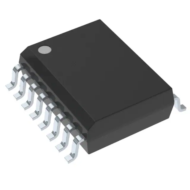
- Part No.:
- S25FL129P0XMFI003
- Manufacturer:
- Cypress Semiconductor Corp
- Category:
- Memory
- Package:
- 16-SOIC (0.295", 7.50mm Width)
- Datasheet:
-
 S25FL129P0XMFI003.pdf
- Description:
- IC FLASH 128MBIT SPI/QUAD 16SOIC
- Quantity:
- Payment:

- Shipping:

Inventory:1,450
Please send an inquiry. Send us your inquiry, and we will respond immediately.
Product details
Overview
S25FL129P0XMFI003 from Cypress Semiconductor is a 128-Mbit (16 MB), single-supply 2.7–3.6 V serial NOR Flash memory with uniform 64 KB sectors and dual/quad I/O support, delivering up to 40 MB/s effective read bandwidth via Quad I/O FAST_READ. It features 100,000 program/erase cycles per sector, 20-year data retention, and integrated OTP (128-bit secure ID + 490-byte user space). Used in industrial control firmware storage and boot code execution for microcontrollers requiring SPI-compatible nonvolatile memory.
For engineers reviewing the S25FL129P0XMFI003 datasheet, S25FL129P0XMFI003 pinout, S25FL129P0XMFI003 application, or S25FL129P0XMFI003 equivalent, key selection criteria include quad I/O timing compliance, 64 KB sub-sector erase granularity, W#/ACC-accelerated programming, and SOIC-16/WSON-8/BGA-24 package compatibility with legacy Spansion/Cypress footprint designs.
Technical Context
The S25FL129P implements a SPI-compatible serial interface with five extended command sets: DOR, QOR, DIOR, QIOR, and QPP - enabling dual/quad input/output operation at up to 80 MHz clock rate. Its architecture supports mixed sectoring: 256 × 64 KB sectors, with top/bottom parameter blocks subdivided into thirty-two 4 KB sub-sectors each.
Internal voltage regulation enables full 2.7–3.6 V operation without external high-voltage supplies, except for accelerated programming which requires 8.5–9.5 V applied to W#/ACC. The device integrates CFI-compliant identification registers, status/configuration registers with BP2–BP0 block protection, and dedicated OTP memory accessible via OTPR/OTPP commands.
Key Specifications
| Parameter | Value and Actual Design Meaning |
|---|---|
| Memory Density | 128 Mbit (16 MB) - sufficient for full MCU boot image + configuration data in space-constrained embedded systems |
| Supply Voltage | 2.7 V to 3.6 V - single-rail compatibility with 3.3 V system rails and brown-out tolerant operation down to 2.7 V |
| Read Throughput | 40 MB/s (Quad I/O FAST_READ @ 80 MHz) - enables sub-400 ms full-image reads for fast boot recovery |
| Program/Erase Endurance | 100,000 cycles per sector - supports field firmware updates over 10+ years in industrial logging applications |
| Data Retention | 20 years typical - ensures long-term reliability of calibration data and security keys without refresh |
| OTP Capacity | 128-bit secure ID + 490-byte user OTP - allows factory-programmed unique device identity and immutable feature licensing flags |
| Erase Granularity | 4 KB sub-sectors (top/bottom 64 KB blocks), 64 KB sectors, 256 KB sectors - enables fine-grained firmware patching without bulk erase latency |
Pinout & Package
Package: 16-pin SOIC (300-mil body width), RoHS-compliant, industry-standard pinout compatible with legacy Spansion S25FL series.
| Pin/Terminal | Circuit Role | Design Meaning |
|---|---|---|
| CS# | Chip Select | Active-low enable for SPI transaction; must fall before first command byte; controls standby-to-active power state transition |
| SCK | Serial Clock | Master-generated clock; rising edge latches SI data, falling edge triggers SO output; max 104 MHz for FAST_READ |
| SI / IO0 | Serial Input / I/O0 | Primary command/address/data input; functions as bidirectional I/O0 in Dual/Quad modes; shares pin with legacy SI |
| SO / IO1 | Serial Output / I/O1 | Primary data output; functions as bidirectional I/O1 in Dual/Quad modes; enables simultaneous read/write in QIOR/QPP |
| W# / ACC / IO2 | Write Protect / Acceleration / I/O2 | Low = write protection; 8.5–9.5 V = accelerated programming; functions as I/O2 in Quad modes for 4-line data transfer |
| HOLD# / IO3 | Hold / I/O3 | Pauses ongoing SPI transfer without deselecting chip; functions as I/O3 in Quad modes; critical for interrupt-safe firmware updates |
| VCC | Power Supply | 2.7–3.6 V main supply; powers internal charge pumps for erase/program; no external HV required except for ACC mode |
| GND | Ground | Reference for all I/O and internal logic; must be low-impedance connection to minimize noise on high-speed Quad I/O lines |
Key Features
| Feature | Design Value |
|---|---|
| Dual/Quad I/O Read Modes | Enables 2×/4× throughput vs standard SPI by using SO, W#/ACC, and HOLD# as active data lines - reduces boot time without changing controller hardware |
| Sub-sector Erase (4 KB) | Allows firmware patching of individual functional modules without erasing adjacent configuration or calibration data - essential for OTA update safety |
| W#/ACC Accelerated Programming | Reduces page program time from ~1.5 ms to <500 µs when 9 V applied - cuts total firmware update duration by >60% in high-volume manufacturing |
| CFI Compliance | Permits automatic detection and configuration by host bootloader via standardized JEDEC query commands - eliminates hard-coded flash parameters in firmware |
| OTP Security Area | Factory- or customer-lockable 128-bit ID + 490-byte region prevents cloning and enables cryptographic key binding to physical hardware |
Applications
| Industrial PLC Firmware Storage | Medical Device Boot Code Execution |
|---|---|
|
Use Scenario: Storing firmware images and runtime configuration for programmable logic controllers operating in harsh EMI environments with wide temperature swings. IC Role / Device Role / Timing Role: Nonvolatile boot memory interfaced directly to ARM Cortex-M7 MCU via Quad SPI; provides deterministic <100 µs access to reset vector and interrupt table. Use Value: 4 KB sub-sector erase enables field updates to motion-control algorithms without corrupting safety-critical I/O mapping tables stored in adjacent sectors. |
Use Scenario: Holding certified bootloader and encrypted application firmware for FDA-class II diagnostic imaging equipment requiring traceable firmware revisions. IC Role / Device Role / Timing Role: Secure boot source verified by hardware crypto engine; OTP area stores immutable device serial number and regulatory certification hash. Use Value: CFI compliance allows same bootloader binary to auto-configure for S25FL129P or successor S25FL128S - simplifies BOM management across product generations. |
| Automotive ADAS Camera Module | Smart Energy Meter Calibration Data |
|
Use Scenario: Storing camera ISP firmware and lens distortion correction profiles in automotive surround-view systems requiring AEC-Q100 Grade 2 qualification. IC Role / Device Role / Timing Role: SPI-connected NOR Flash providing <500 ns random access to pixel pipeline configuration registers during sensor initialization. Use Value: 20-year data retention ensures calibration data remains valid over full vehicle lifetime without battery-backed SRAM or periodic refresh. |
Use Scenario: Archiving metrology-grade calibration coefficients and tamper-evident usage logs in ANSI C12.20-certified smart electricity meters deployed in utility substations. IC Role / Device Role / Timing Role: Write-once-read-many storage for factory-calibrated ADC gain/offset values; OTP locks coefficients against unauthorized modification. Use Value: 100,000-cycle endurance supports daily firmware patches and monthly log rotation over 10+ years of field operation. |
Equivalent & Alternatives
The following parts are listed as comparable options for similar serial NOR flash memory applications.
| Alternative Part | Technical Difference | Application Difference | Selection Advice |
|---|---|---|---|
| S25FL128SAGMFI000 | Successor device; identical 128 Mbit density, 2.7–3.6 V, SOIC-16 package; adds 133 MHz Quad I/O, enhanced ECC, and improved deep power-down current (1 µA vs 3 µA) | Supports higher-speed boot in next-gen controllers; backward-compatible pinout but requires updated timing parameters in driver code | Select for new designs requiring longer lifecycle support and lower active/standby power - Cypress confirms full migration path including software register mapping |
| MX25L12833FZNI-10G | 128 Mbit, 2.7–3.6 V, SOIC-16; supports 104 MHz Quad I/O but lacks W#/ACC acceleration and OTP security area; only 64 KB sector erase (no 4 KB sub-sectors) | Suitable for cost-sensitive consumer applications where firmware update granularity and secure ID are not required | Choose when budget constraints outweigh need for sub-sector erase or hardware-enforced device identity - verify absence of OTP dependency in existing firmware |
Compared with S25FL129P0XMFI003, the S25FL128S offers measurable improvements in speed and power efficiency while maintaining pin and command compatibility, whereas the MX25L12833F sacrifices sub-sector flexibility and security features for lower unit cost in non-critical applications.
Availability
S25FL129P0XMFI003 is available at Aetrix Electronics and suitable for industrial PLC firmware storage, medical device boot code execution, and automotive ADAS camera module applications requiring stable component supply and long-term obsolescence management.
Supply support for S25FL129P0XMFI003 includes scheduled delivery planning, volume procurement assistance, BOM continuity management, traceable sourcing, and lifecycle availability coordination for OEM customers, industrial embedded developers, connected-device designers, and electronics production programs.
Manufacturer
Cypress Semiconductor, founded in 1982 and now part of Infineon Technologies, delivers high-performance embedded solutions including PSoC, microcontrollers, analog ICs, and reliable NOR/NAND flash memory for automotive, industrial, and consumer systems.
The S25FL129P belongs to Cypress's Spansion-branded serial NOR Flash product line, engineered specifically for robust firmware storage and secure boot in mission-critical embedded systems demanding long data retention and field-upgrade capability.
FAQ
Is S25FL129P0XMFI003 still recommended for new designs?
No. Cypress explicitly states this part is not recommended for new or current designs. The factory-recommended migration path is S25FL128S, which offers higher performance, lower power, and continued production support. S25FL129P remains available for legacy design support and repair, but no new design-in should occur.
What is the function of the W#/ACC pin beyond write protection?
The W#/ACC pin serves three roles: (1) write protection when pulled low, (2) acceleration trigger when 8.5–9.5 V is applied to reduce page program time by >60%, and (3) I/O2 in Quad I/O modes for 4-line data transfer. It is not a dedicated high-voltage pin - voltage must be externally generated and gated only during programming sequences.
Does S25FL129P0XMFI003 support Quad SPI mode out-of-the-box?
Yes, but requires configuration. The device defaults to standard SPI mode after power-up. Quad I/O operation must be enabled by setting QUAD bit (bit 6) in the Configuration Register using the WRR command. Once set, QIOR and QPP commands become active, and SI/SO/W#/HOLD# operate as bidirectional data lines.
How is the 4 KB sub-sector erase implemented physically?
The 4 KB sub-sector erase applies only to the two parameter blocks (top or bottom 64 KB sectors), each subdivided into thirty-two 4 KB units. This is implemented via internal address decoding and segmented erase transistors - no external hardware changes are needed. The P4E command (20h) targets these sub-sectors exclusively; standard SE (D8h) erases full 64 KB or 256 KB sectors.
S25FL129P0XMFI003 Specifications
- Product attributes
- Attribute value
- Manufacturer:
- Cypress Semiconductor Corp
- Series:
- FL-P
- Package/Case:
- 16-SOIC (0.295", 7.50mm Width)
- Packaging:
- Tape & Reel (TR)
- Product Status:
- Obsolete
- Programmable:
- Not Verified
- Memory Type:
- Non-Volatile
- Memory Format:
- FLASH
- Technology:
- FLASH - NOR
- Memory Size:
- 128Mbit
- Memory Organization:
- 16M x 8
- Memory Interface:
- SPI - Quad I/O
- Clock Frequency:
- 104 MHz
- Write Cycle Time - Word, Page:
- 5µs, 3ms
- Access Time:
- -
- Voltage - Supply:
- 2.7V ~ 3.6V
- Operating Temperature:
- -40°C ~ 85°C (TA)
- Grade:
- -
- Qualification:
- -
- Mounting Type:
- Surface Mount
- Supplier Device Package:
- 16-SOIC
S25FL129P0XMFI003 FAQ
1.How can I place an order for S25FL129P0XMFI003 through Aetrix?
Please submit a Request for Quotation (RFQ) for S25FL129P0XMFI003 on Aetrix. Our sales agent will provide a competitive quotation and guide you through the order confirmation once you accept the terms.
2.Are the price and stock information for S25FL129P0XMFI003 reliable?
The price and inventory of S25FL129P0XMFI003 are updated periodically and may fluctuate due to market conditions. Stock and pricing data are typically refreshed every 24 hours. Quotation validity for S25FL129P0XMFI003 is usually 5 days.
3.What payment methods are accepted for S25FL129P0XMFI003?
We accept Wire Transfer, PayPal, Credit Card, Western Union, MoneyGram, and Escrow for S25FL129P0XMFI003 transactions.
Note: Certain payment methods may incur a processing fee.
4.How is shipping managed for S25FL129P0XMFI003?
S25FL129P0XMFI003 orders can be shipped via leading logistics carriers, including DHL, UPS, FedEx, TNT, or Registered Mail.
Once your S25FL129P0XMFI003 order is processed, you will receive an email with the shipment details and tracking number.
Note: Tracking information may take up to 24 hours to appear. Express delivery typically takes 3–5 business days.
5.How can I obtain technical support or documentation for S25FL129P0XMFI003?
For technical support, including S25FL129P0XMFI003 datasheets, pinout diagrams, or application guidance, please contact our engineering support team. They can provide detailed documentation and assistance for your S25FL129P0XMFI003 requirements.
6.How does Aetrix verify that S25FL129P0XMFI003 is sourced from the original manufacturer or authorized distributors?
All S25FL129P0XMFI003 products on Aetrix are procured from qualified distributors and authorized channels. Our dedicated quality assurance team conducts strict verification, including traceability checks and, if necessary, third-party testing. This ensures that S25FL129P0XMFI003 meets industry standards.
7.What is the process for return or replacement of S25FL129P0XMFI003?
All S25FL129P0XMFI003 units undergo pre-shipment inspection (PSI). If there is an issue with S25FL129P0XMFI003, returns or replacements are accepted under the following conditions:
1.Quantity discrepancies, incorrect items, or visible external defects (such as breakage or corrosion), acknowledged by Aetrix.
2.The issue is reported within 90 days of delivery.
3.The S25FL129P0XMFI003 part is unused and in its original packaging.
Return procedure for S25FL129P0XMFI003:
1.Submit a request within 90 days.
2.Obtain a Return Material Authorization (RMA) from Aetrix.
S25FL129P0XMFI003 Tags

-
M24C02-WMN6TP
STMicroelectronics

-
AT24C02C-XHM-T
Microchip Technology

-
AT21CS01-STUM10-T
Microchip Technology

-
AT24C02C-SSHM-T
Microchip Technology

-
24LC01BT-I/OT
Microchip Technology

-
M24C02-FMC6TG
STMicroelectronics
-
AT24CS02-SSHM-T
Microchip Technology

-
93LC46BT-I/OT
Microchip Technology
-
AT24C04C-SSHM-T
Microchip Technology

-
24LC01BT-I/SN
Microchip Technology
-
24AA02UIDT-I/OT
Microchip Technology

-
AT24C08C-STUM-T
Microchip Technology
Tech Hub

Hall effect sensor guide covering working principle, linear and digital sensors, Arduino circuits, current sensing, speed detection, automotive applications, A3144 examples, signal filtering and datash…

Product Change Notification guide for electronic components, covering PCN meaning, PCN vs PDN/EOL, common change types, risk levels, form-fit-function review, engineering validation, BOM control, LTB/L…

A practical guide to blend door actuators, covering HVAC function, symptoms, location, AC and heater issues, reset and calibration, replacement cost, electrical diagnosis, compatibility checks, and rep…

Engineering guide to Raspberry Pi alternatives, covering chip-level differences, Orange Pi, ROCK, Jetson, Banana Pi, NanoPi, Compute Module, Pico, GPIO, camera, HAT compatibility, and replacement risks…

Engineering guide to dynamic load response testing for high-current buck converters, covering load step setup, slew rate, Vcore undershoot, overshoot, recovery time, probe location, output capacitors a…

Engineering guide to output capacitor selection for ASIC Vcore rails, covering bulk capacitors, polymer capacitors, MLCC decoupling, DC bias, ESR, ESL, placement, transient response and substitution ri…

Engineering guide to high-current ASIC Vcore rails, covering 12-phase buck architecture, PMBus control, dynamic load testing, output capacitor networks, smart power stage selection, thermal design and …

Voltage regulator guide covering linear, LDO, 7805, Zener, adjustable, buck, VRM and alternator regulators, with design checks, testing methods, troubleshooting and datasheet-based selection.

Amplifier guide covering voltage, current and power amplification, gain, feedback, amplifier classes, audio and RF applications, op-amp circuits, transimpedance amplifiers, datasheet selection and trou…

Machine vision system guide covering components, inspection workflow, camera and lens selection, FOV, pixel resolution, motion blur, strobe lighting, bandwidth, 2D/3D vision, integration, troubleshooti…


