
 My Inquiry
 My Account


Cypress Semiconductor Corp S70FL01GSDPMFV010
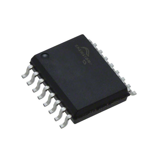
- Part No.:
- S70FL01GSDPMFV010
- Manufacturer:
- Cypress Semiconductor Corp
- Category:
- Memory
- Package:
- 16-SOIC (0.295", 7.50mm Width)
- Datasheet:
-
 S70FL01GSDPMFV010.pdf
- Description:
- IC FLASH 1GBIT SPI/QUAD 16SOIC
- Quantity:
- Payment:

- Shipping:

Inventory:7,923
Please send an inquiry. Send us your inquiry, and we will respond immediately.
Product details
Overview
S70FL01GSDPMFV010 from Infineon is a 1 Gbit (128 Mbyte) dual-die SPI flash memory with Multi-I/O interface, 3.0 V core supply, uniform 256-kbyte sectors, and support for Quad DDR read commands. It implements two stacked S25FL512S dies with independent CS1# and CS2# control, enabling discrete die addressing in industrial and automotive systems requiring high-density nonvolatile storage.
For engineers reviewing the S70FL01GSDPMFV010 datasheet, S70FL01GSDPMFV010 pinout, S70FL01GSDPMFV010 application, or S70FL01GSDPMFV010 equivalent, key selection criteria include dual-die address management, sector erase independence per die, OTP array size, AEC-Q100 Grade 2 qualification, and SOIC-16 vs. BGA-24 package compatibility.
Technical Context
The S70FL01GSDPMFV010 integrates two independent 512 Mbit FL-S flash dies sharing a common SPI bus but controlled via separate chip select lines (CS1# and CS2#). Each die maintains its own status register, configuration register, bank address register, and block protection logic.
It supports extended 32-bit addressing, AutoBoot from preselected addresses, Common Flash Interface (CFI) data, and simultaneous die operation only in sequential access mode-not true interleaved reads. VIO is RFU and not supported; I/O voltage range is 1.65–3.6 V, while core operates at 2.7–3.6 V.
Key Specifications
| Parameter | Value and Actual Design Meaning |
|---|---|
| Memory density | 1 Gbit (128 Mbyte), implemented as dual 512 Mbit dies |
| Interface | SPI Multi-I/O with support for Normal/Fast/Dual/Quad/DDR read modes |
| Programming speed | 1.5 Mbytes/s using 512-byte page buffer and Quad-input programming |
| Erase granularity | Uniform 256-kbyte sectors; bulk erase requires separate command per die |
| Endurance & retention | 100,000 program-erase cycles; 20-year data retention at ≤85°C |
| Security features | 2048-byte OTP array; hardware/software block protection; advanced sector protection (ASP) |
| Operating temperature | AEC-Q100 Grade 2 (−40°C to +105°C); Industrial Plus grade also supported |
Pinout & Package
Package: 16-lead SOIC (300 mils), Pb-free, with VIO pin marked RFU (not functional).
| Pin/Terminal | Circuit Role | Design Meaning |
|---|---|---|
| CS1# | Chip Select 1 | Selects first 512 Mbit die; enables independent command execution on Die 1 |
| CS2# | Chip Select 2 | Selects second 512 Mbit die; required for full 1 Gbit addressing |
| SI/IO0 | Serial Input / IO0 | Single-bit input or Quad I/O line 0; supports standard and multi-I/O protocols |
| SO/IO1 | Serial Output / IO1 | Single-bit output or Quad I/O line 1; used in Dual/Quad read/write operations |
| WP#/IO2 | Write Protect / IO2 | Hardware write protection in single/dual mode; IO2 in Quad mode; internal pull-up |
| HOLD#/IO3 | Hold / IO3 | Pauses ongoing serial transfer; IO3 in Quad-I/O mode; internal pull-up |
| SCK | Serial Clock | Drives SPI timing; supports both SDR and DDR clocking modes |
| RESET# | Hardware Reset | Asynchronous reset to standby state; internal pull-up; optional connection |
| VCC | Core Supply | 2.7–3.6 V core power; powers flash array and control logic |
| VSS | Ground | Reference return path for all signals and supplies |
Key Features
| Feature | Design Value |
|---|---|
| Dual-die architecture | Two independent S25FL512S dies with separate CS#, status registers, and erase domains |
| AutoBoot functionality | Executes Normal or Quad read automatically at power-up/reset from user-configurable address |
| Extended 32-bit addressing | Enables full 1 Gbit linear address space without bank switching overhead |
| Common Flash Interface (CFI) | Provides standardized configuration metadata for host firmware auto-detection and initialization |
| OTP security array | 2048-byte one-time-programmable region for keys, calibration data, or secure boot code |
Applications
| Automotive ADAS ECU | Industrial PLC Firmware Storage |
|---|---|
Use Scenario: Storing boot firmware and real-time sensor calibration tables in radar processing units. IC Role / Device Role / Timing Role: Nonvolatile code and configuration storage with AEC-Q100 Grade 2 qualification and 105°C operation. Use Value: Enables fail-safe boot under thermal stress; OTP array secures calibration parameters against field overwrite. | Use Scenario: Holding programmable logic controller (PLC) runtime firmware and I/O mapping tables. IC Role / Device Role / Timing Role: High-reliability SPI flash for deterministic firmware load during cold start and watchdog recovery. Use Value: Uniform 256-kbyte sectors allow atomic firmware updates; dual-die structure isolates boot loader from application image. |
| Medical Imaging Boot Loader | Telecom Base Station Configuration |
Use Scenario: Hosting secure boot loader and FPGA bitstream in portable ultrasound devices. IC Role / Device Role / Timing Role: Trusted storage for cryptographic verification of boot images before execution. Use Value: 20-year data retention ensures long-term calibration validity; ASP and block protection prevent accidental corruption. | Use Scenario: Storing radio configuration profiles and protocol stack parameters in 5G remote radio units. IC Role / Device Role / Timing Role: High-speed Quad DDR read capability reduces boot latency in time-critical baseband initialization. Use Value: 1.5 Mbytes/s programming speed accelerates field firmware upgrades; CFI support simplifies multi-vendor toolchain integration. |
Equivalent & Alternatives
The following parts are listed as comparable options for similar SPI flash memory applications.
| Alternative Part | Technical Difference | Application Difference | Selection Advice |
|---|---|---|---|
| S25FL128SAGMFV001 | Single-die 128 Mbyte device; no CS2#; no dual-die coordination overhead | Limited to 128 Mbyte; unsuitable for >128 Mbyte firmware or dual-image storage | Select when system requires simpler address management and lower density suffices |
| S70FL01GSAGMFB010 | BGA-24 (ZSA024) package; same dual-die architecture and feature set | Requires PCB redesign for 8×6 mm BGA footprint; better thermal performance in compact layouts | Select for space-constrained designs where SOIC-16 is mechanically incompatible |
Compared with S25FL128SAGMFV001, the S70FL01GSDPMFV010 delivers 8× higher density with die-select flexibility but adds complexity in sector erase and status register synchronization; versus S70FL01GSAGMFB010, it offers identical functionality in a through-hole SOIC-16 package for legacy board compatibility.
Availability
S70FL01GSDPMFV010 is available at Aetrix Electronics and suitable for automotive ADAS ECUs, industrial PLCs, medical imaging systems, and telecom base stations requiring stable component supply across extended temperature ranges and long product lifecycles.
Supply support for S70FL01GSDPMFV010 includes scheduled delivery planning, volume procurement assistance, BOM continuity management, traceable sourcing, and lifecycle availability coordination for OEM customers, industrial embedded developers, connected-device designers, and electronics production programs.
Manufacturer
Infineon Technologies is a German semiconductor manufacturer specializing in power management, automotive microcontrollers, and nonvolatile memory solutions for mission-critical applications.
The FL-S family targets high-reliability embedded systems needing SPI flash with enhanced security, extended temperature operation, and scalable density-designed specifically for automotive, industrial, and medical platforms demanding AEC-Q100 compliance and long-term data integrity.
FAQ
What is the function of CS1# and CS2# on the S70FL01GSDPMFV010?
CS1# and CS2# are independent chip select inputs that activate the first and second 512 Mbit flash dies respectively. Each die operates autonomously: commands issued while CS1# is asserted affect only Die 1, and those with CS2# active target Die 2. This enables discrete addressing and avoids cross-die interference during programming or erase.
Does the S70FL01GSDPMFV010 support true interleaved reads across both dies?
No. Sequential reads crossing the boundary between Die 1 and Die 2 are not supported. To read across the full 1 Gbit address space, the host must issue separate read commands-first using CS1# for addresses 0x00000000–0x07FFFFFF, then CS2# for 0x08000000–0x0FFFFFFF-with explicit address management.
Is the VIO pin functional on this part?
No. The VIO pin is marked RFU (Reserved for Future Use) and is not supported in the S70FL01GSDPMFV010. I/O voltage is derived solely from VCC (2.7–3.6 V), and the VIO/RFU pin must be left unconnected or tied to VSS per datasheet guidance; it has no electrical function.
How does the OTP array differ from standard flash sectors?
The 2048-byte OTP array is physically isolated and programmed once using dedicated commands. Unlike regular sectors, it cannot be erased or rewritten after programming. It is intended for immutable data such as cryptographic keys, device-specific calibration values, or secure boot signatures-ensuring tamper-resistant storage independent of firmware updates.
S70FL01GSDPMFV010 Specifications
- Product attributes
- Attribute value
- Manufacturer:
- Cypress Semiconductor Corp
- Series:
- FL-S
- Package/Case:
- 16-SOIC (0.295", 7.50mm Width)
- Packaging:
- Tray
- Product Status:
- Active
- Programmable:
- Not Verified
- Memory Type:
- Non-Volatile
- Memory Format:
- FLASH
- Technology:
- FLASH - NOR
- Memory Size:
- 1Gbit
- Memory Organization:
- 128M x 8
- Memory Interface:
- SPI - Quad I/O
- Clock Frequency:
- 66 MHz
- Write Cycle Time - Word, Page:
- -
- Access Time:
- -
- Voltage - Supply:
- 2.7V ~ 3.6V
- Operating Temperature:
- -40°C ~ 105°C (TA)
- Grade:
- -
- Qualification:
- -
- Mounting Type:
- Surface Mount
- Supplier Device Package:
- 16-SOIC
S70FL01GSDPMFV010 FAQ
1.How can I place an order for S70FL01GSDPMFV010 through Aetrix?
Please submit a Request for Quotation (RFQ) for S70FL01GSDPMFV010 on Aetrix. Our sales agent will provide a competitive quotation and guide you through the order confirmation once you accept the terms.
2.Are the price and stock information for S70FL01GSDPMFV010 reliable?
The price and inventory of S70FL01GSDPMFV010 are updated periodically and may fluctuate due to market conditions. Stock and pricing data are typically refreshed every 24 hours. Quotation validity for S70FL01GSDPMFV010 is usually 5 days.
3.What payment methods are accepted for S70FL01GSDPMFV010?
We accept Wire Transfer, PayPal, Credit Card, Western Union, MoneyGram, and Escrow for S70FL01GSDPMFV010 transactions.
Note: Certain payment methods may incur a processing fee.
4.How is shipping managed for S70FL01GSDPMFV010?
S70FL01GSDPMFV010 orders can be shipped via leading logistics carriers, including DHL, UPS, FedEx, TNT, or Registered Mail.
Once your S70FL01GSDPMFV010 order is processed, you will receive an email with the shipment details and tracking number.
Note: Tracking information may take up to 24 hours to appear. Express delivery typically takes 3–5 business days.
5.How can I obtain technical support or documentation for S70FL01GSDPMFV010?
For technical support, including S70FL01GSDPMFV010 datasheets, pinout diagrams, or application guidance, please contact our engineering support team. They can provide detailed documentation and assistance for your S70FL01GSDPMFV010 requirements.
6.How does Aetrix verify that S70FL01GSDPMFV010 is sourced from the original manufacturer or authorized distributors?
All S70FL01GSDPMFV010 products on Aetrix are procured from qualified distributors and authorized channels. Our dedicated quality assurance team conducts strict verification, including traceability checks and, if necessary, third-party testing. This ensures that S70FL01GSDPMFV010 meets industry standards.
7.What is the process for return or replacement of S70FL01GSDPMFV010?
All S70FL01GSDPMFV010 units undergo pre-shipment inspection (PSI). If there is an issue with S70FL01GSDPMFV010, returns or replacements are accepted under the following conditions:
1.Quantity discrepancies, incorrect items, or visible external defects (such as breakage or corrosion), acknowledged by Aetrix.
2.The issue is reported within 90 days of delivery.
3.The S70FL01GSDPMFV010 part is unused and in its original packaging.
Return procedure for S70FL01GSDPMFV010:
1.Submit a request within 90 days.
2.Obtain a Return Material Authorization (RMA) from Aetrix.
S70FL01GSDPMFV010 Tags

-
M24C02-WMN6TP
STMicroelectronics

-
AT24C02C-XHM-T
Microchip Technology

-
AT21CS01-STUM10-T
Microchip Technology

-
AT24C02C-SSHM-T
Microchip Technology

-
24LC01BT-I/OT
Microchip Technology

-
M24C02-FMC6TG
STMicroelectronics
-
AT24CS02-SSHM-T
Microchip Technology

-
93LC46BT-I/OT
Microchip Technology
-
AT24C04C-SSHM-T
Microchip Technology

-
24LC01BT-I/SN
Microchip Technology
-
24AA02UIDT-I/OT
Microchip Technology

-
AT24C08C-STUM-T
Microchip Technology
Tech Hub

Hall effect sensor guide covering working principle, linear and digital sensors, Arduino circuits, current sensing, speed detection, automotive applications, A3144 examples, signal filtering and datash…

Product Change Notification guide for electronic components, covering PCN meaning, PCN vs PDN/EOL, common change types, risk levels, form-fit-function review, engineering validation, BOM control, LTB/L…

A practical guide to blend door actuators, covering HVAC function, symptoms, location, AC and heater issues, reset and calibration, replacement cost, electrical diagnosis, compatibility checks, and rep…

Engineering guide to Raspberry Pi alternatives, covering chip-level differences, Orange Pi, ROCK, Jetson, Banana Pi, NanoPi, Compute Module, Pico, GPIO, camera, HAT compatibility, and replacement risks…

Engineering guide to dynamic load response testing for high-current buck converters, covering load step setup, slew rate, Vcore undershoot, overshoot, recovery time, probe location, output capacitors a…

Engineering guide to output capacitor selection for ASIC Vcore rails, covering bulk capacitors, polymer capacitors, MLCC decoupling, DC bias, ESR, ESL, placement, transient response and substitution ri…

Engineering guide to high-current ASIC Vcore rails, covering 12-phase buck architecture, PMBus control, dynamic load testing, output capacitor networks, smart power stage selection, thermal design and …

Voltage regulator guide covering linear, LDO, 7805, Zener, adjustable, buck, VRM and alternator regulators, with design checks, testing methods, troubleshooting and datasheet-based selection.

Amplifier guide covering voltage, current and power amplification, gain, feedback, amplifier classes, audio and RF applications, op-amp circuits, transimpedance amplifiers, datasheet selection and trou…

Machine vision system guide covering components, inspection workflow, camera and lens selection, FOV, pixel resolution, motion blur, strobe lighting, bandwidth, 2D/3D vision, integration, troubleshooti…


