
 My Inquiry
 My Account


Infineon Technologies TT310N26KOFHPSA1
- Part No.:
- TT310N26KOFHPSA1
- Manufacturer:
- Infineon Technologies
- Category:
- SCRs - Modules
- Package:
- Module
- Datasheet:
-
 TT310N26KOFHPSA1.pdf
- Description:
- SCR MODULE 2.6KV 700A MODULE
- Quantity:
- Payment:

- Shipping:

Inventory:2,713
Please send an inquiry. Send us your inquiry, and we will respond immediately.
Product details
Overview
TT310N26KOFHPSA1 from Infineon Technologies is a phase-control thyristor module rated for 2600 V repetitive peak off-state voltage (VDRM/VRRM), 310 A average on-state current (ITAVM) at TC = 85°C, and 700 A RMS on-state current (ITRMSM). It features dual thyristor arms in press-pack construction with AlN ceramic isolation, designed for high-power AC line commutated rectification and motor speed control in industrial medium-voltage drives.
For engineers reviewing the TT310N26KOFHPSA1 datasheet, TT310N26KOFHPSA1 pinout, TT310N26KOFHPSA1 application, or TT310N26KOFHPSA1 equivalent, key selection criteria include verified gate trigger current (IGT ≤ 250 mA), critical dv/dt rating (1000 V/µs), junction-to-case thermal resistance (0.0373 °C/W per arm), and surge current capability (9000 A, tP = 10 ms).
Technical Context
This device implements a dual-arm, reverse-blocking thyristor configuration optimized for B2 (two-pulse) and B6 (six-pulse) bridge topologies. Its press-pack Si-pellet design with mechanical clamping ensures low contact resistance (rT = 0.86 mΩ) and stable thermal performance under high di/dt (120 A/µs) and dv/dt stress.
Thermal management relies on direct copper baseplate mounting with specified case-to-heatsink resistance (RthCH ≤ 0.02 °C/W per arm). The module supports natural and forced cooling, with transient thermal impedance data provided for sinusoidal and rectangular conduction angles (0°–180°) to enable accurate loss and temperature modeling.
Key Specifications
| Parameter | Value and Actual Design Meaning |
|---|---|
| VDRM/VRRM | 2600 V - Maximum repetitive blocking voltage per thyristor arm, enabling use in 2.3 kV AC line systems with safety margin. |
| ITAVM @ TC = 85°C | 310 A - Continuous DC or average forward current per arm, defining steady-state power handling in rectifier bridges. |
| ITRMSM | 700 A - RMS on-state current rating, used to calculate conduction losses under real-world AC waveforms. |
| ITSM (tP = 10 ms) | 9000 A - Non-repetitive surge current at maximum junction temperature, supporting short-circuit withstand in drive inverters. |
| (dv/dt)cr | 1000 V/µs - Minimum required rate-of-rise of off-state voltage before false triggering, critical for snubberless operation. |
| RthJC (per arm, DC) | 0.0373 °C/W - Junction-to-case thermal resistance, directly determining maximum allowable power dissipation at given case temperature. |
| vT max @ iT = 1300 A | 2.22 V - Maximum on-state voltage drop, used to compute conduction losses (P = vT × iT) in thermal design. |
Pinout & Package
TT310N26KOFHPSA1 is housed in a press-pack module with isolated copper baseplate and two electrically independent thyristor arms. Mechanical terminals are M2 (12 Nm torque) for main anode/cathode connections and DIN 46244 A (2.8 × 0.8 mm) for gate control leads. Internal isolation uses aluminum nitride (AlN) ceramic.
| Pin/Terminal | Circuit Role | Design Meaning |
|---|---|---|
| A1 / K1 | Anode/Cathode Arm 1 | Main power terminals for first thyristor arm; rated for full ITAVM and VDRM; requires torque-controlled M2 fastening. |
| A2 / K2 | Anode/Cathode Arm 2 | Main power terminals for second thyristor arm; fully isolated from Arm 1; enables dual-arm B2/B6 bridge configurations. |
| G1 / K1 | Gate 1 / Cathode 1 | Low-energy gate trigger input for Arm 1; requires IGT ≤ 250 mA and VGT ≤ 1.5 V to ensure reliable turn-on. |
| G2 / K2 | Gate 2 / Cathode 2 | Independent gate input for Arm 2; galvanically isolated from G1/K1; supports asynchronous or synchronized firing schemes. |
Key Features
| Feature | Design Value |
|---|---|
| Press-pack Si-pellet construction | Eliminates wire bonds and solder layers, delivering stable RthJC and high di/dt immunity (120 A/µs) over lifetime. |
| AlN ceramic internal isolation | Provides 3.6 kV insulation test voltage (1 sec) and 19 mm creepage distance, meeting IEC 60747-6 for industrial safety. |
| Rated for B2 and B6 bridge topologies | Validated current derating curves support both two-pulse and six-pulse rectification up to 1200 A output in forced-cooled systems. |
| Gate non-trigger voltage (VGD) | ≤ 0.2 V at 0.5 VDRM, ensuring noise immunity against false turn-on during high dv/dt transients. |
| Transient thermal impedance model | Supplied analytical ZthJC coefficients (7-term Foster network) for precise dynamic thermal simulation in SPICE or MATLAB. |
Applications
| Industrial AC Motor Drives | Medium-Voltage Rectifier Systems |
|---|---|
Use Scenario: Speed-controlled induction motors in steel mill rolling stands operating from 3.3 kV AC supply. IC Role / Device Role / Timing Role: Thyristor arm in B6 six-pulse phase-controlled rectifier converting AC to regulated DC bus for DC drive converter stage. Use Value: 2600 V VDRM and 9000 A ITSM enable direct connection to 3.3 kV grid with single-stage conversion, reducing system complexity and transformer count. | Use Scenario: Electrolysis power supply for aluminum smelting requiring 50 kA DC at 600 V. IC Role / Device Role / Timing Role: Parallel-connected thyristor module in multi-pulse rectifier bank, sharing load via matched RthJC and vT characteristics. Use Value: 0.0373 °C/W RthJC (DC) and 0.86 mΩ rT minimize thermal imbalance and conduction loss across parallel strings, improving efficiency and reliability. |
| High-Power UPS Input Stages | DC Arc Furnace Controllers |
Use Scenario: Regenerative input rectifier in 2 MW double-conversion UPS feeding critical data center loads. IC Role / Device Role / Timing Role: Bidirectional B6 bridge thyristor module enabling controlled regeneration during utility overvoltage events. Use Value: 300 µs tq (turn-off time) and 1000 V/µs (dv/dt)cr support safe commutation into inductive UPS input filters without external snubbers. | Use Scenario: Electrode current control in 150-ton DC arc furnace with 60 kA electrode current and rapid load transients. IC Role / Device Role / Timing Role: Phase-angle controlled thyristor module regulating electrode power by adjusting conduction angle in B2 topology. Use Value: 120 A/µs (di/dt)cr and 1500 mA latching current (IL) ensure robust turn-on under high-inductance furnace secondary circuits. |
Equivalent & Alternatives
The following parts are listed as comparable options for similar phase-control thyristor module applications.
| Alternative Part | Technical Difference | Application Difference | Selection Advice |
|---|---|---|---|
| TT330N22KOFHPSA1 | Lower VDRM/VRRM (2200 V), higher ITAVM (330 A), same package and gate specs. | Suitable for 1.7 kV AC systems; requires additional series stacking for 2.3 kV+ applications. | Select when system voltage is ≤ 2.0 kV and higher average current is prioritized over blocking voltage headroom. |
| TT122N26KOFHPSA1 | Same VDRM/VRRM (2600 V), lower ITAVM (122 A), reduced ITRMSM (280 A), smaller thermal resistance (0.029 °C/W). | Targeted at lower-power B2 bridges or single-arm auxiliary converters where footprint and cost are constrained. | Choose for space-constrained designs needing identical voltage rating but <200 A average load, with tighter thermal budget. |
Compared with TT310N26KOFHPSA1, TT330N22KOFHPSA1 trades 400 V blocking margin for +20 A average current, while TT122N26KOFHPSA1 retains full 2600 V rating in a thermally superior but lower-current package-enabling scalable design across 122–310 A power tiers within identical mechanical interface.
Availability
TT310N26KOFHPSA1 is available at Aetrix Electronics and suitable for industrial AC motor drives, medium-voltage rectifier systems, and high-power UPS input stages requiring stable component supply and long-lifecycle support.
Supply support for TT310N26KOFHPSA1 includes scheduled delivery planning, volume procurement assistance, BOM continuity management, traceable sourcing, and lifecycle availability coordination for OEM customers, industrial embedded developers, connected-device designers, and electronics production programs.
Manufacturer
Infineon Technologies is a German semiconductor manufacturer specializing in power semiconductors, microcontrollers, and sensor solutions for industrial, automotive, and energy markets.
This part belongs to Infineon's "Netz-Thyristor-Modul" product line, engineered specifically for high-reliability, high-current phase-controlled rectification in industrial power conversion systems operating up to 125°C junction temperature.
FAQ
What is the maximum junction temperature and how does it affect derating?
The maximum junction temperature (Tvj max) is 125°C. Derating curves in the datasheet define allowable ITAVM versus case temperature (TC) for sinusoidal and rectangular conduction angles. At TC = 85°C, ITAVM = 310 A; above this, current must be linearly reduced to maintain Tvj ≤ 125°C using RthJC = 0.0373 °C/W.
Does TT310N26KOFHPSA1 require external snubbers in B6 bridge operation?
Snubbers are not mandatory due to its high (dv/dt)cr of 1000 V/µs and validated tq = 300 µs at full load. However, RC snubbers are recommended for systems with stray inductance > 1 µH or when operating near VDRM limits to suppress voltage overshoot during commutation.
How is gate drive isolation implemented for dual-arm operation?
Each arm has fully isolated gate terminals (G1/K1 and G2/K2) referenced to its respective cathode. Gate drive circuits must provide independent, floating supplies referenced to each cathode potential. No shared gate reference is permitted; common-mode voltage between arms may exceed 1000 V during commutation.
What mechanical mounting torque values are specified for main and gate terminals?
Main power terminals (A1/K1, A2/K2) require M2 screws tightened to 12 Nm ±10%. Gate terminals conform to DIN 46244 A (2.8 × 0.8 mm) and must be secured with appropriate crimp or screw terminals-no torque specification is given for gate leads, but mechanical retention must prevent vibration-induced disconnection under 50 m/s² vibration per DIN EN 60068-2-6.
TT310N26KOFHPSA1 Specifications
- Product attributes
- Attribute value
- Manufacturer:
- Infineon Technologies
- Series:
- -
- Package/Case:
- Module
- Packaging:
- Bulk
- Product Status:
- Obsolete
- Structure:
- Series Connection - All SCRs
- Number of SCRs, Diodes:
- 2 SCRs
- Voltage - Off State:
- 2.6 kV
- Current - On State (It (AV)) (Max):
- 446 A
- Current - On State (It (RMS)) (Max):
- 700 A
- Voltage - Gate Trigger (Vgt) (Max):
- 1.5 V
- Current - Gate Trigger (Igt) (Max):
- 250 mA
- Current - Non Rep. Surge 50, 60Hz (Itsm):
- 10000A @ 50Hz
- Current - Hold (Ih) (Max):
- 300 mA
- Operating Temperature:
- -40°C ~ 125°C
- Grade:
- -
- Qualification:
- -
- Mounting Type:
- Chassis Mount
TT310N26KOFHPSA1 FAQ
1.How can I place an order for TT310N26KOFHPSA1 through Aetrix?
Please submit a Request for Quotation (RFQ) for TT310N26KOFHPSA1 on Aetrix. Our sales agent will provide a competitive quotation and guide you through the order confirmation once you accept the terms.
2.Are the price and stock information for TT310N26KOFHPSA1 reliable?
The price and inventory of TT310N26KOFHPSA1 are updated periodically and may fluctuate due to market conditions. Stock and pricing data are typically refreshed every 24 hours. Quotation validity for TT310N26KOFHPSA1 is usually 5 days.
3.What payment methods are accepted for TT310N26KOFHPSA1?
We accept Wire Transfer, PayPal, Credit Card, Western Union, MoneyGram, and Escrow for TT310N26KOFHPSA1 transactions.
Note: Certain payment methods may incur a processing fee.
4.How is shipping managed for TT310N26KOFHPSA1?
TT310N26KOFHPSA1 orders can be shipped via leading logistics carriers, including DHL, UPS, FedEx, TNT, or Registered Mail.
Once your TT310N26KOFHPSA1 order is processed, you will receive an email with the shipment details and tracking number.
Note: Tracking information may take up to 24 hours to appear. Express delivery typically takes 3–5 business days.
5.How can I obtain technical support or documentation for TT310N26KOFHPSA1?
For technical support, including TT310N26KOFHPSA1 datasheets, pinout diagrams, or application guidance, please contact our engineering support team. They can provide detailed documentation and assistance for your TT310N26KOFHPSA1 requirements.
6.How does Aetrix verify that TT310N26KOFHPSA1 is sourced from the original manufacturer or authorized distributors?
All TT310N26KOFHPSA1 products on Aetrix are procured from qualified distributors and authorized channels. Our dedicated quality assurance team conducts strict verification, including traceability checks and, if necessary, third-party testing. This ensures that TT310N26KOFHPSA1 meets industry standards.
7.What is the process for return or replacement of TT310N26KOFHPSA1?
All TT310N26KOFHPSA1 units undergo pre-shipment inspection (PSI). If there is an issue with TT310N26KOFHPSA1, returns or replacements are accepted under the following conditions:
1.Quantity discrepancies, incorrect items, or visible external defects (such as breakage or corrosion), acknowledged by Aetrix.
2.The issue is reported within 90 days of delivery.
3.The TT310N26KOFHPSA1 part is unused and in its original packaging.
Return procedure for TT310N26KOFHPSA1:
1.Submit a request within 90 days.
2.Obtain a Return Material Authorization (RMA) from Aetrix.
TT310N26KOFHPSA1 Tags
-
MCC95-16IO1B
IXYS
-
TT190N16SOFHPSA2
Infineon Technologies
-
MCC162-16IO1
IXYS
-
B612F-2T
Sensata-Crydom
-
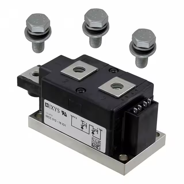
MCC312-16IO1
IXYS
-
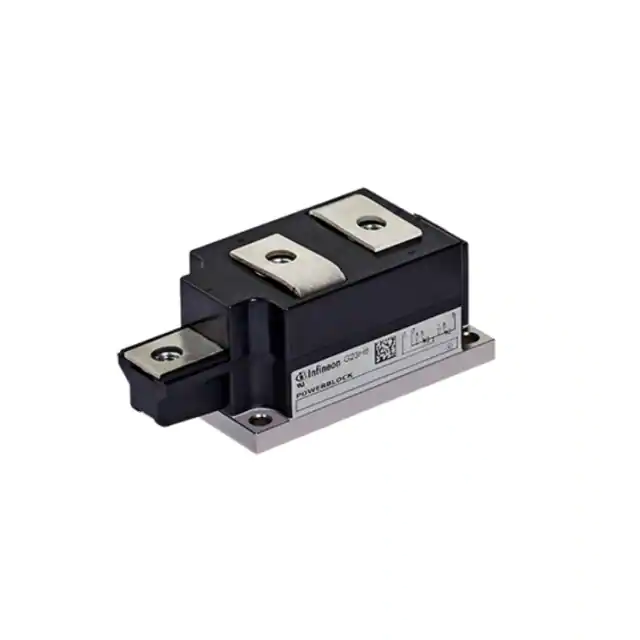
TT250N16KOFHPSA1
Infineon Technologies
-
CLA60PD1200NA
IXYS
-
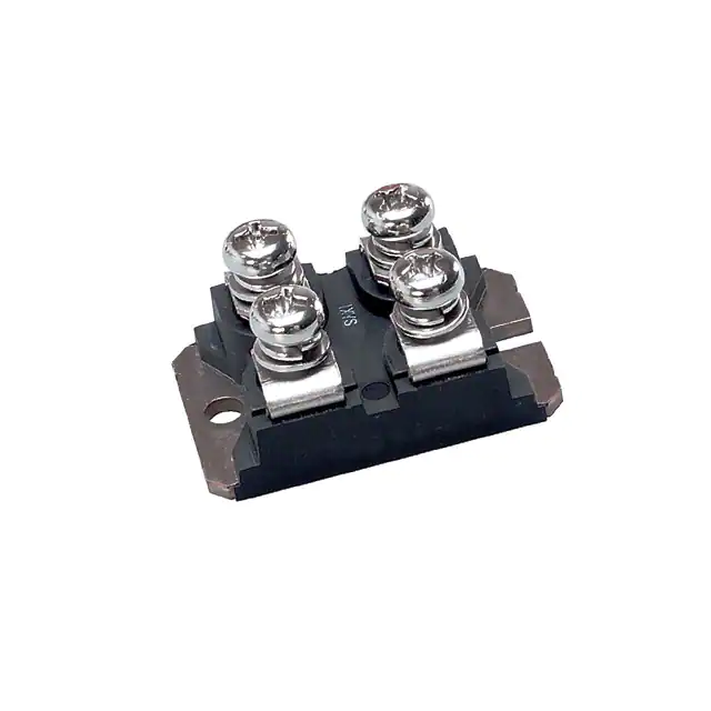
MCC56-16IO1B
IXYS
-
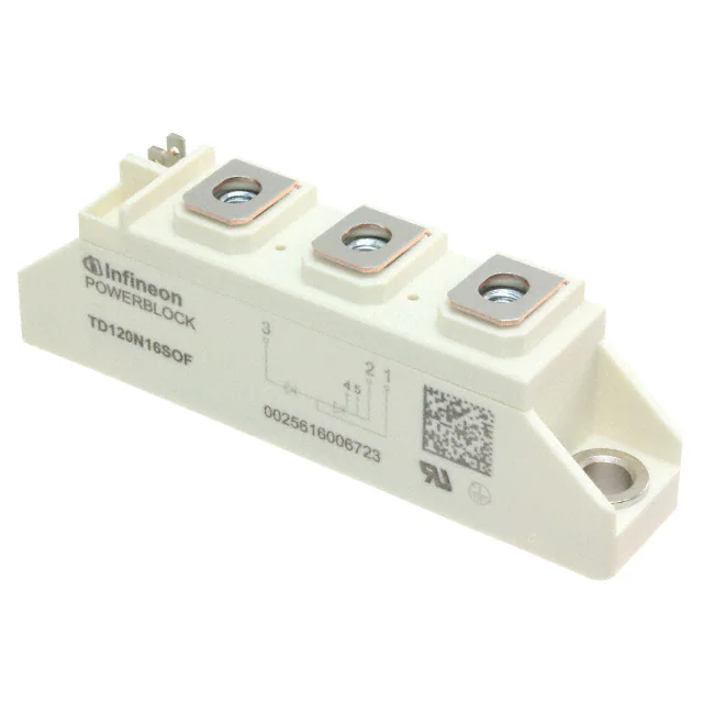
TD120N16SOFHPSA1
Infineon Technologies
-
MCC95-12IO1B
IXYS
-
MCMA140P1600TA
IXYS
-
B512F-2
Sensata-Crydom
Tech Hub

18650 battery guide covering lithium-ion cell basics, 3.6V/3.7V voltage, 4.2V charging, mAh and Wh capacity, protected cells, chargers, BMS, series-parallel packs, holders, welding and sourcing checks.…

Hall effect sensor guide covering working principle, linear and digital sensors, Arduino circuits, current sensing, speed detection, automotive applications, A3144 examples, signal filtering and datash…

Product Change Notification guide for electronic components, covering PCN meaning, PCN vs PDN/EOL, common change types, risk levels, form-fit-function review, engineering validation, BOM control, LTB/L…

A practical guide to blend door actuators, covering HVAC function, symptoms, location, AC and heater issues, reset and calibration, replacement cost, electrical diagnosis, compatibility checks, and rep…

Engineering guide to Raspberry Pi alternatives, covering chip-level differences, Orange Pi, ROCK, Jetson, Banana Pi, NanoPi, Compute Module, Pico, GPIO, camera, HAT compatibility, and replacement risks…

Engineering guide to dynamic load response testing for high-current buck converters, covering load step setup, slew rate, Vcore undershoot, overshoot, recovery time, probe location, output capacitors a…

Engineering guide to output capacitor selection for ASIC Vcore rails, covering bulk capacitors, polymer capacitors, MLCC decoupling, DC bias, ESR, ESL, placement, transient response and substitution ri…

Engineering guide to high-current ASIC Vcore rails, covering 12-phase buck architecture, PMBus control, dynamic load testing, output capacitor networks, smart power stage selection, thermal design and …

Voltage regulator guide covering linear, LDO, 7805, Zener, adjustable, buck, VRM and alternator regulators, with design checks, testing methods, troubleshooting and datasheet-based selection.

Amplifier guide covering voltage, current and power amplification, gain, feedback, amplifier classes, audio and RF applications, op-amp circuits, transimpedance amplifiers, datasheet selection and trou…


