
 My Inquiry
 My Account


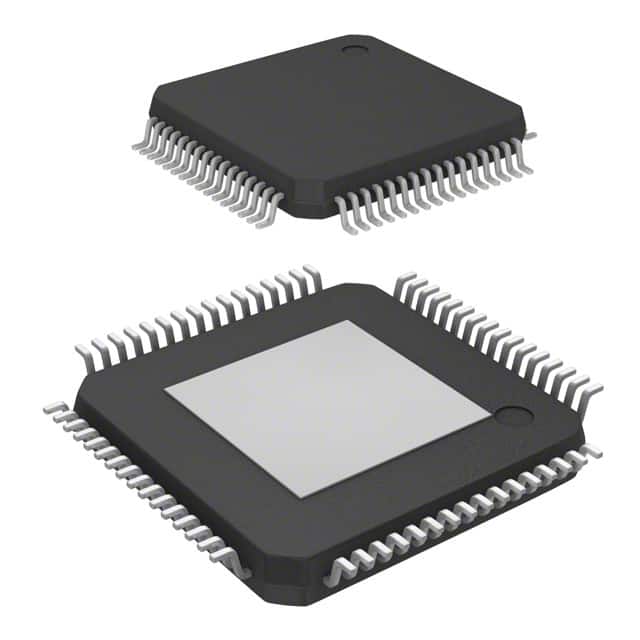
Infineon Technologies XMC1402F064X0128AAXUMA1
- Part No.:
- XMC1402F064X0128AAXUMA1
- Manufacturer:
- Infineon Technologies
- Category:
- Microcontrollers
- Package:
- 64-LQFP Exposed Pad
- Datasheet:
-
 XMC1402F064X0128AAXUMA1.pdf
- Description:
- IC MCU 32BIT 128KB FLASH 64LQFP
- Quantity:
- Payment:

- Shipping:

Inventory:1,308
Please send an inquiry. Send us your inquiry, and we will respond immediately.
Product details
Overview
XMC1402F064X0128AAXUMA1 from Infineon Technologies is an ARM® Cortex®-M0 32-bit microcontroller optimized for industrial real-time control, featuring 128 KB Flash, 16 KB SRAM with parity, and a 48 MHz CPU clock. It integrates dual 12-bit ADCs (up to 1.1 MS/s), two CCU8 timer units for complementary PWM generation, and MultiCAN+ with two nodes and 32 message objects - deployed in motor drive inverters and digital power supplies.
For engineers reviewing the XMC1402F064X0128AAXUMA1 datasheet, XMC1402F064X0128AAXUMA1 pinout, XMC1402F064X0128AAXUMA1 application, or XMC1402F064X0128AAXUMA1 equivalent, key selection considerations include its 96 MHz CCU8 timer base, 1.8–5.5 V supply range, 48-pin LQFP package, and support for single-pin bootloader and secure SBSL.
Technical Context
The device implements a deterministic real-time architecture centered on dual CCU8 modules (each with four 16-bit channels) capable of generating synchronized, phase-shifted, and dead-time-controlled PWM signals for three-phase motor control and resonant LLC converters. Its analog subsystem includes two independent VADC kernels with 12-bit resolution, sample-and-hold stages, and 0–5.5 V input range - enabling direct sensing of high-side current shunts without external signal conditioning.
Communication is handled via two USIC modules (four total channels), configurable as UART, SPI (single/dual/quad), IIC, IIS, or LIN - with hardware-accelerated protocol handling and up to 12 Mb/s data rates. The integrated MultiCAN+ controller supports full-CAN and Basic-CAN modes at up to 1 MBaud, with dedicated message object RAM and hardware filtering for robust fieldbus integration.
Key Specifications
| Parameter | Value and Actual Design Meaning |
|---|---|
| CPU Core | ARM Cortex-M0 @ 48 MHz; delivers 0.84 DMIPS/MHz (Dhrystone 2.1), suitable for deterministic motor control loops ≤20 µs. |
| Flash Memory | 128 KB with ECC protection; enables safe firmware updates and runtime code integrity verification in safety-critical drives. |
| SRAM | 16 KB with parity checking; supports fault-tolerant variable storage for real-time control state and PID coefficients. |
| ADC Performance | 2 × 12-bit VADC kernels, 1.1 MS/s aggregate sampling rate, 0–5.5 V input range - eliminates need for external level-shifting in 24 V industrial sensor interfaces. |
| PWM Timing Resolution | CCU8 timers run at 96 MHz base clock; achieves 10.4 ns timing granularity for precise gate driver dead-time insertion and phase alignment. |
| Operating Voltage | 1.8 V to 5.5 V single-supply operation; allows direct interfacing with 3.3 V logic, 5 V analog sensors, and 24 V industrial I/O without level translators. |
| Temperature Range | -40 °C to +105 °C ambient; qualified for under-hood motor control and factory-floor power conversion environments. |
Pinout & Package
This device is housed in a 64-pin LQFP package (12 mm × 12 mm, 0.5 mm pitch), with exposed thermal pad for enhanced heat dissipation in high-power density motor control PCB layouts.
| Pin/Terminal | Circuit Role | Design Meaning |
|---|---|---|
| VDDP / VSSP | Core Power / Ground | Dedicated 1.8 V supply pins for CPU and digital logic; decoupling required within 10 mm for stable 48 MHz operation. |
| VDDA / VSSA | Analog Power / Ground | Separate 5.0 V analog domain supply; isolates noise-sensitive ADC and comparator circuits from digital switching transients. |
| P0.0–P0.15 | General-purpose I/O | Up to 50 mA sink capability per pin; supports direct LED driving and high-current GPIO loads without external buffers. |
| CCU8x.OUTy | PWM Output | Hardware-generated complementary PWM outputs with programmable dead time (1–255 ns steps); routed to external gate drivers. |
| ADC0.IN0–ADC0.IN11 | Analog Input | Dedicated analog input channels with internal sample-and-hold; supports simultaneous sampling across multiple phases in PMSM FOC. |
| CAN0.TX / CAN0.RX | CAN Bus Interface | Differential CAN physical layer interface compliant with ISO 11898-2; supports 1 MBaud bit rate with built-in bus arbitration and error handling. |
Key Features
| Feature | Design Value |
|---|---|
| Dual CCU8 Timer Units | Each provides four 16-bit channels with center-aligned PWM, flexible trigger sources, and hardware dead-time insertion - essential for synchronous rectification and multi-phase inverter control. |
| MultiCAN+ Controller | Two independent CAN nodes with 32 message objects, hardware acceptance filtering, and FIFO buffering - enables distributed motor control networks with minimal CPU overhead. |
| Integrated LEDTS Module | Supports up to 24 capacitive touch pads and drives 144 LEDs via BCCU; used for HMI panels in industrial HMIs without external touch controllers. |
| Secure Bootloader (SBSL) | Optional factory-programmed secure bootstrap loader supporting cryptographic signature verification - ensures only authenticated firmware executes on power-up. |
| MATH Coprocessor | Hardware CORDIC engine for 24-bit trigonometric functions and 32-bit integer division - accelerates field-oriented control (FOC) computations by >10× vs. software-only implementation. |
Applications
| Brushless DC Motor Drive | Digital Power Supply Control |
|---|---|
|
Use Scenario: Closed-loop commutation and torque regulation for 3-phase BLDC motors in HVAC blowers and industrial pumps. IC Role / Device Role / Timing Role: Real-time execution of FOC algorithm, generation of six-channel complementary PWM with <100 ns dead-time accuracy, and ADC-synchronized current sampling. Use Value: Enables >95% efficiency and <5% torque ripple using on-chip CCU8 and VADC - eliminating external PWM generators and analog front-end ICs. |
Use Scenario: Adaptive voltage regulation in telecom rectifiers and server PSUs with dynamic load transient response. IC Role / Device Role / Timing Role: High-speed ADC sampling (1.1 MS/s) of output voltage/current, PID loop execution at 200 kHz, and USIC-driven PMBus communication. Use Value: Achieves ±0.5% output regulation and <100 µs load-step recovery using integrated analog peripherals and deterministic interrupt latency. |
| Industrial HMI Panel | LED Lighting Control System |
|
Use Scenario: Touch-enabled operator interface with status indicators and parameter adjustment for PLC-connected machinery. IC Role / Device Role / Timing Role: Capacitive touch sensing (LEDTS), LED dimming control (BCCU), and CAN-based host communication (MultiCAN+). Use Value: Integrates touch, lighting, and fieldbus into one chip - reducing BOM count by 4 ICs and simplifying EMC layout for CE-compliant panels. |
Use Scenario: Multi-channel color-mixing and thermal derating for architectural LED fixtures with DALI or DMX interfaces. IC Role / Device Role / Timing Role: BCCU-managed brightness/color control across 144 LEDs, temperature-compensated dimming via on-die TSE, and USIC-based DALI transceiver. Use Value: Maintains CCT stability ±100K over 0–85°C ambient using integrated temperature sensor and closed-loop PWM feedback - no external thermal management IC needed. |
Equivalent & Alternatives
The following parts are listed as comparable options for similar industrial microcontroller applications.
| Alternative Part | Technical Difference | Application Difference | Selection Advice |
|---|---|---|---|
| XMC1402F064X0064AAXUMA1 | 64 KB Flash (vs. 128 KB); identical peripherals, package, and timing specs. | Suitable for simpler motor control firmware with <64 KB code footprint; lacks space for dual-bank OTA updates. | Select when firmware size is confirmed ≤56 KB and field upgrade via bootloader is not required. |
| XMC1404F064X0128AAXUMA1 | Adds second MultiCAN+ node (2×2 nodes/64 MOs); same Flash/SRAM/peripherals otherwise. | Required for daisy-chained multi-axis motion systems needing isolated CAN domains (e.g., CNC tool changers). | Choose only if dual independent CAN buses are mandatory - adds cost and routing complexity without benefit for single-drive use cases. |
Compared with XMC1402F064X0064AAXUMA1, this part enables secure dual-bank firmware updates and larger control algorithms; versus XMC1404F064X0128AAXUMA1, it reduces CAN routing overhead and bill-of-materials cost where single-bus topology suffices.
Availability
XMC1402F064X0128AAXUMA1 is available at Aetrix Electronics and suitable for industrial motor drives, digital power supplies, and LED lighting control systems requiring stable component supply across extended product lifecycles.
Supply support for XMC1402F064X0128AAXUMA1 includes scheduled delivery planning, volume procurement assistance, BOM continuity management, traceable sourcing, and lifecycle availability coordination for OEM customers, industrial embedded developers, connected-device designers, and electronics production programs.
Manufacturer
Infineon Technologies is a German semiconductor manufacturer specializing in power management, automotive, and industrial control ICs, with leadership in silicon carbide and embedded control solutions.
This device belongs to the XMC1400 AA-Step series - designed specifically for deterministic real-time control in motor drives, digital power conversion, and intelligent lighting, emphasizing hardware-accelerated peripherals and functional safety readiness.
FAQ
What debug interfaces does XMC1402F064X0128AAXUMA1 support?
The device supports ARM Serial Wire Debug (SWD) with four hardware breakpoints and two watchpoints, plus a single-pin debug interface for minimal PCB footprint. It does not support JTAG. SWD operates at up to 24 MHz and is compatible with standard CMSIS-DAP debug probes and Infineon's DASLink tools.
Does this MCU include hardware security features beyond SBSL?
Yes - it integrates a pseudo-random number generator (PRNG) compliant with NIST SP 800-90A, memory protection unit (MPU) with eight regions, and flash lock bits for read/write protection. Secure boot relies on factory-programmed SBSL; user firmware can implement additional layers using MPU and PRNG for key derivation.
Can the on-chip oscillators meet timing requirements for CAN communication?
The internal fast oscillator (FOSC) is rated at ±2% accuracy over temperature and voltage - insufficient for CAN bit timing at 1 MBaud. For full CAN compliance, an external 4–20 MHz crystal must be used with the on-chip PLL to generate a stable system clock; the datasheet specifies 8 MHz ±0.2% crystal for 1 MBaud operation.
How many independent PWM outputs can be generated simultaneously?
Using both CCU8 units (CCU80 and CCU81), the device supports up to eight independent PWM channels with full complementary pair control, dead-time insertion, and synchronization. Each CCU8 provides four 16-bit channels, and all eight can operate concurrently with independent period/duty-cycle registers and event-triggered updates.
XMC1402F064X0128AAXUMA1 Specifications
- Product attributes
- Attribute value
- Manufacturer:
- Infineon Technologies
- Package/Case:
- 64-LQFP Exposed Pad
- Series:
- XMC1000
- Packaging:
- Tape & Reel (TR)
- Product Status:
- Active
- Programmable:
- Not Verified
- Core Processor:
- ARM® Cortex®-M0
- Core Size:
- 32-Bit Single-Core
- Speed:
- 48MHz
- Connectivity:
- I2C, LINbus, SPI, UART/USART
- Peripherals:
- Brown-out Detect/Reset, I2S, POR, PWM, WDT
- Number of I/O:
- 48
- Program Memory Size:
- 128KB (128K x 8)
- Program Memory Type:
- FLASH
- EEPROM Size:
- -
- RAM Size:
- 16K x 8
- Voltage - Supply (Vcc/Vdd):
- 1.8V ~ 5.5V
- Data Converters:
- A/D 12x12b
- Oscillator Type:
- Internal
- Operating Temperature:
- -40°C ~ 105°C (TA)
- Grade:
- -
- Qualification:
- -
- Mounting Type:
- Surface Mount
- Supplier Device Package:
XMC1402F064X0128AAXUMA1 FAQ
1.How can I place an order for XMC1402F064X0128AAXUMA1 through Aetrix?
Please submit a Request for Quotation (RFQ) for XMC1402F064X0128AAXUMA1 on Aetrix. Our sales agent will provide a competitive quotation and guide you through the order confirmation once you accept the terms.
2.Are the price and stock information for XMC1402F064X0128AAXUMA1 reliable?
The price and inventory of XMC1402F064X0128AAXUMA1 are updated periodically and may fluctuate due to market conditions. Stock and pricing data are typically refreshed every 24 hours. Quotation validity for XMC1402F064X0128AAXUMA1 is usually 5 days.
3.What payment methods are accepted for XMC1402F064X0128AAXUMA1?
We accept Wire Transfer, PayPal, Credit Card, Western Union, MoneyGram, and Escrow for XMC1402F064X0128AAXUMA1 transactions.
Note: Certain payment methods may incur a processing fee.
4.How is shipping managed for XMC1402F064X0128AAXUMA1?
XMC1402F064X0128AAXUMA1 orders can be shipped via leading logistics carriers, including DHL, UPS, FedEx, TNT, or Registered Mail.
Once your XMC1402F064X0128AAXUMA1 order is processed, you will receive an email with the shipment details and tracking number.
Note: Tracking information may take up to 24 hours to appear. Express delivery typically takes 3–5 business days.
5.How can I obtain technical support or documentation for XMC1402F064X0128AAXUMA1?
For technical support, including XMC1402F064X0128AAXUMA1 datasheets, pinout diagrams, or application guidance, please contact our engineering support team. They can provide detailed documentation and assistance for your XMC1402F064X0128AAXUMA1 requirements.
6.How does Aetrix verify that XMC1402F064X0128AAXUMA1 is sourced from the original manufacturer or authorized distributors?
All XMC1402F064X0128AAXUMA1 products on Aetrix are procured from qualified distributors and authorized channels. Our dedicated quality assurance team conducts strict verification, including traceability checks and, if necessary, third-party testing. This ensures that XMC1402F064X0128AAXUMA1 meets industry standards.
7.What is the process for return or replacement of XMC1402F064X0128AAXUMA1?
All XMC1402F064X0128AAXUMA1 units undergo pre-shipment inspection (PSI). If there is an issue with XMC1402F064X0128AAXUMA1, returns or replacements are accepted under the following conditions:
1.Quantity discrepancies, incorrect items, or visible external defects (such as breakage or corrosion), acknowledged by Aetrix.
2.The issue is reported within 90 days of delivery.
3.The XMC1402F064X0128AAXUMA1 part is unused and in its original packaging.
Return procedure for XMC1402F064X0128AAXUMA1:
1.Submit a request within 90 days.
2.Obtain a Return Material Authorization (RMA) from Aetrix.
XMC1402F064X0128AAXUMA1 Tags

-
ATTINY4-TSHR
Microchip Technology
-
ATTINY10-TSHR
Microchip Technology
-
ATTINY10-TS8R
Microchip Technology

-
ATTINY202-SSNR
Microchip Technology
-
ATTINY202-SSFR
Microchip Technology
-
ATTINY402-SSNR
Microchip Technology

-
PIC16F15213T-I/MF
Microchip Technology
-
PIC16F15213-E/MF
Microchip Technology

-
PIC10F200T-I/OT
Microchip Technology
-
ATTINY412-SSNR
Microchip Technology
-
PIC10F202T-I/OT
Microchip Technology

-
ATTINY404-SSNR
Microchip Technology
Tech Hub

18650 battery guide covering lithium-ion cell basics, 3.6V/3.7V voltage, 4.2V charging, mAh and Wh capacity, protected cells, chargers, BMS, series-parallel packs, holders, welding and sourcing checks.…

Hall effect sensor guide covering working principle, linear and digital sensors, Arduino circuits, current sensing, speed detection, automotive applications, A3144 examples, signal filtering and datash…

Product Change Notification guide for electronic components, covering PCN meaning, PCN vs PDN/EOL, common change types, risk levels, form-fit-function review, engineering validation, BOM control, LTB/L…

A practical guide to blend door actuators, covering HVAC function, symptoms, location, AC and heater issues, reset and calibration, replacement cost, electrical diagnosis, compatibility checks, and rep…

Engineering guide to Raspberry Pi alternatives, covering chip-level differences, Orange Pi, ROCK, Jetson, Banana Pi, NanoPi, Compute Module, Pico, GPIO, camera, HAT compatibility, and replacement risks…

Engineering guide to dynamic load response testing for high-current buck converters, covering load step setup, slew rate, Vcore undershoot, overshoot, recovery time, probe location, output capacitors a…

Engineering guide to output capacitor selection for ASIC Vcore rails, covering bulk capacitors, polymer capacitors, MLCC decoupling, DC bias, ESR, ESL, placement, transient response and substitution ri…

Engineering guide to high-current ASIC Vcore rails, covering 12-phase buck architecture, PMBus control, dynamic load testing, output capacitor networks, smart power stage selection, thermal design and …

Voltage regulator guide covering linear, LDO, 7805, Zener, adjustable, buck, VRM and alternator regulators, with design checks, testing methods, troubleshooting and datasheet-based selection.

Amplifier guide covering voltage, current and power amplification, gain, feedback, amplifier classes, audio and RF applications, op-amp circuits, transimpedance amplifiers, datasheet selection and trou…


