
 My Inquiry
 My Account


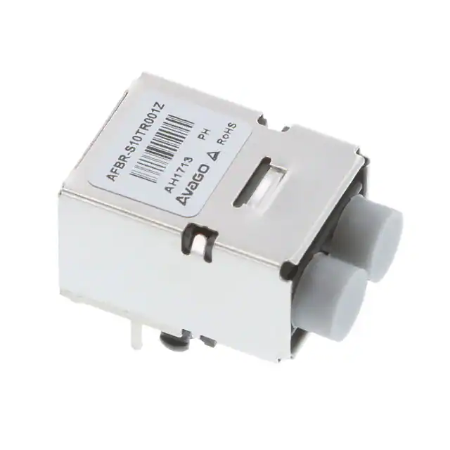
Broadcom Limited AFBR-S10TR001Z
- Part No.:
- AFBR-S10TR001Z
- Manufacturer:
- Broadcom Limited
- Category:
- Fiber Optic Transceiver Modules
- Package:
- Datasheet:
-
 AFBR-S10TR001Z.pdf
- Description:
- TX FIBER OPTIC POF
- Quantity:
- Payment:

- Shipping:

Inventory:2,467
Please send an inquiry. Send us your inquiry, and we will respond immediately.
Product details
Overview
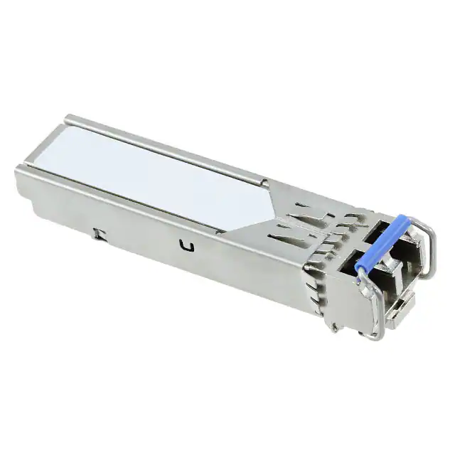
AFBR-S10TR001Z from Broadcom (formerly Avago Technologies) is a compact 650 nm analog optical transceiver for arc flash detection over 1 mm Plastic Optical Fiber (POF), integrating a 650 nm LED transmitter and a photodiode + TIA receiver in one package, operating from -40°C to +85°C with RoHS compliance and Versatile-Link duplex connector.
For engineers reviewing the AFBR-S10TR001Z datasheet, pinout, applications, or equivalent options, key selection considerations include its analog output voltage linearity vs. optical input power (-35 dBm to 0 dBm), 75 V/µs slew rate, 40 ns pulse rise time, ESD robustness (2 kV HBM), and compatibility with simplex Versatile-Link connectors in safety-critical POF sensing systems.
Technical Context
The transmitter uses a directly current-driven 650 nm LED with peak emission between 630–685 nm and spectral width ≤30 nm, delivering up to 2 dBm optical power into 1 mm POF at 30 mA DC drive. Its optical rise/fall times are each ≤100 ns under simple driver conditions.
The receiver integrates a PIN photodiode and linear transimpedance amplifier (TIA) in a single ASIC, producing an analog output voltage proportional to incident optical power across 300–1100 nm range, with responsivity of 30–70 V/mW at 650 nm, 40 ns rise/60 ns fall time, and ±0.5 µs pulse width distortion in linear operation.
Key Specifications
| Parameter | Value and Actual Design Meaning |
|---|---|
| Transmitter Wavelength | 650 nm center (630–685 nm range); optimized for high coupling efficiency into 1 mm POF with NA=0.5. |
| Receiver Responsivity | 30–70 V/mW at 650 nm; enables direct analog voltage readout without external amplification for -35 to 0 dBm optical input. |
| Output Slew Rate | 75 V/µs; supports fast transient optical event capture (e.g., arc flash onset) without signal distortion. |
| Pulse Rise/Fall Time | 40 ns / 60 ns (10–90%); ensures accurate timing fidelity for sub-microsecond optical pulse detection. |
| Operating Temperature | -40°C to +85°C case temperature; validated for industrial arc flash sensor deployment in harsh electrical environments. |
| ESD Robustness | 2000 V HBM on all pins; sustains handling and board-level ESD events common in utility switchgear installations. |
| Optical Connector | Versatile-Link duplex; mechanically keyed, backward-compatible with existing simplex Versatile-Link infrastructure. |
Pinout & Package
The AFBR-S10TR001Z uses a custom surface-mount housing with 8 signal pins, 4 isolated EMI shield solder posts, and 2 un-plated mounting posts. Dimensions: 21.45 × 12.6 × 7.35 mm (L×W×H). Shield posts connect to chassis ground; mounting posts provide mechanical retention.
| Pin/Terminal | Circuit Role | Design Meaning |
|---|---|---|
| 1 (LED_A) | LED Anode | Direct current drive input for 650 nm LED; requires external current-limiting resistor (e.g., 560 Ω). |
| 2 (LED_C) | LED Cathode | Return path for LED drive current; connects to system ground. |
| 3, 5 (GND) | Analog Ground | Dual ground connections reduce noise coupling between transmitter and receiver sections. |
| 4 (VCC) | Receiver Supply | 5 V ±5% supply for TIA and photodiode bias; decoupling required (10 µF + 100 nF). |
| 6 (VOUT) | Analog Output | Linear voltage output (0–4 V) proportional to optical input power; drives 500 Ω load. |
| 7, 8 (N.C.) | No Connect | Unbonded pins; must remain unconnected per design-no internal circuitry attached. |
Key Features
| Feature | Design Value |
|---|---|
| Integrated Self-Test LED | Enables in-system optical path verification without external light source-critical for arc flash sensor functional safety checks. |
| High EMI Robustness | Validated immunity to 15 V/m RF field (8 MHz–1 GHz); maintains signal integrity in electrically noisy switchgear cabinets. |
| Compact RJ-45 Form Factor | 21.45 mm length matches standard Ethernet jack footprint-enables drop-in integration into existing panel-mount cutouts. |
| Class 1 Laser Safety | Complies with EN 60825-1:2007; no user-accessible hazardous radiation-permits use in unshielded industrial enclosures. |
| RoHS & UL Recognized | Lead-free construction and UL File E173874 certification support global regulatory acceptance for safety-critical infrastructure. |
Applications
| Arc Flash Detection | Switchgear Monitoring |
|---|---|
Use Scenario: Real-time detection of ultraviolet/visible light bursts during high-energy electrical arcing inside medium-voltage switchgear cabinets. IC Role / Device Role / Timing Role: Optical transceiver converting arc light intensity into analog voltage signal for microcontroller ADC sampling at ≥100 kHz. Use Value: Enables <100 µs response latency from arc initiation to trip signal generation, meeting IEEE C37.20.7 arc-flash mitigation requirements. | Use Scenario: Continuous optical monitoring of busbar compartments for incipient fault development via ambient light change analysis. IC Role / Device Role / Timing Role: Analog front-end providing linear voltage output proportional to POF-coupled light intensity for trend-based anomaly detection. Use Value: Supports predictive maintenance algorithms using stable 40–60 ns pulse fidelity and -35 to 0 dBm dynamic range over full temperature range. |
| Transformer Protection | Generator Circuit Breaker Sensing |
Use Scenario: Mounting inside oil-immersed transformer tanks to detect internal arcing through fiber-optic feedthroughs. IC Role / Device Role / Timing Role: Hermetically sealed optical interface converting localized arc photons into voltage for remote relay logic. Use Value: Delivers Class 1 eye safety and -40°C to +85°C operation without thermal drift compensation-reducing calibration overhead. | Use Scenario: Integration into generator circuit breaker trip units to sense arc faults during high-current interruption events. IC Role / Device Role / Timing Role: Fast-response analog transceiver feeding dedicated protection ASIC with calibrated optical amplitude data. Use Value: Provides 75 V/µs slew rate and 2 kV HBM ESD rating to survive electromagnetic transients near high-current contacts. |
Equivalent & Alternatives
The following parts are listed as comparable options for similar optical transceiver applications.
| Alternative Part | Technical Difference | Application Difference | Selection Advice |
|---|---|---|---|
| AFBR-S11TR001Z | Same package and pinout; higher transmitter output (+2 dBm vs. +2 dBm typ), identical receiver specs. | Identical arc flash use cases; preferred when margin for fiber loss or aging is required. | Select AFBR-S11TR001Z for extended POF runs (>5 m) or dirty-fiber environments where higher launch power improves SNR. |
| HFD2010 | Discrete LED+TIA solution in SOIC-8; no integrated Versatile-Link connector; requires external optics alignment. | Suitable for PCB-integrated designs but lacks plug-and-play POF interface; no built-in self-test LED. | Choose HFD2010 only when custom optical path design and cost optimization outweigh need for rapid deployment and safety certification. |
Compared with AFBR-S10TR001Z, AFBR-S11TR001Z offers identical form, fit, and function with higher optical output margin, while HFD2010 requires full optical subsystem engineering but provides greater flexibility in wavelength and gain tuning.
Availability
AFBR-S10TR001Z is available at Aetrix Electronics and suitable for arc flash detection, switchgear monitoring, and transformer protection requiring stable component supply, long-term lifecycle support, and RoHS-compliant optical sensing solutions.
Supply support for AFBR-S10TR001Z includes scheduled delivery planning, volume procurement assistance, BOM continuity management, traceable sourcing, and lifecycle availability coordination for OEM customers, industrial embedded developers, connected-device designers, and electronics production programs.
Manufacturer
Broadcom Inc. (formerly Avago Technologies) is a global semiconductor leader specializing in wired and wireless communications, enterprise storage, and industrial optoelectronics.
The AFBR-S10TR001Z belongs to Broadcom's Versatile-Link optical transceiver product line, engineered specifically for safety-critical, high-reliability POF-based sensing in electrical utility and industrial power systems.
FAQ
What is the maximum optical input power the AFBR-S10TR001Z receiver can handle without saturation?
The AFBR-S10TR001Z receiver operates linearly up to approximately 0 dBm optical input power, beyond which overdrive effects occur. Pulse width distortion exceeds ±0.5 µs above -10 dBm, and maximum output voltage is capped at 4 V. For sustained linear operation, optical input should be kept ≤ -5 dBm; the device tolerates short pulses up to 0 dBm with measurable but bounded distortion. Always refer to Figure 7 and Figure 8 in the AFBR-S10TR001Z datasheet for logarithmic and linear transfer curves.
Can the AFBR-S10TR001Z be used with multimode glass fiber instead of POF?
No-the AFBR-S10TR001Z is optically optimized for 1 mm Plastic Optical Fiber (POF) with numerical aperture 0.5. Its LED emitter and receiver lensing are designed for large-core, low-cost POF coupling; using it with 50/125 µm or 62.5/125 µm glass fiber results in >20 dB coupling loss and unreliable signal levels. The AFBR-S10TR001Z datasheet explicitly specifies POF compatibility and does not characterize performance with glass fiber.
Does the AFBR-S10TR001Z require external components for basic operation?
Yes-the AFBR-S10TR001Z requires at minimum: (1) a current-limiting resistor (e.g., 560 Ω) on LED_A to set drive current, (2) 10 µF + 100 nF bypass capacitors on VCC, and (3) proper grounding of both GND pins and shield posts to chassis. Figure 4 in the AFBR-S10TR001Z datasheet shows the recommended application circuit. No external amplification is needed for the VOUT signal within its specified load and voltage range.
Is the AFBR-S10TR001Z compliant with IEC 61000-4-3 for radiated immunity?
Yes-the AFBR-S10TR001Z has been tested per IEC 61000-4-3 and demonstrates no measurable functional degradation when exposed to a 15 V/m radiated field swept from 8 MHz to 1 GHz, provided it is mounted on a circuit board without a chassis enclosure. This immunity level is documented in the Regulatory Compliance Table of the AFBR-S10TR001Z datasheet and supports deployment in electrically noisy substations and industrial control panels.
How is the AFBR-S10TR001Z's self-test capability implemented?
The AFBR-S10TR001Z implements self-test via its integrated LED: driving LED_A/LED_C with appropriate current illuminates the internal optical path, allowing the receiver section to generate a known VOUT voltage. This verifies end-to-end functionality-including fiber continuity, connector mating, and analog signal chain integrity-without external equipment. The test is performed at system power-up or on-demand, and the resulting voltage is compared against expected range (e.g., ~2.5 V at 30 mA drive) to confirm health of the AFBR-S10TR001Z optical link.
AFBR-S10TR001Z Specifications
- Product attributes
- Attribute value
- Manufacturer:
- Broadcom Limited
- Series:
- -
- Packaging:
- Bulk
- Product Status:
- Active
- Data Rate:
- -
- Wavelength:
- 650nm
- Applications:
- -
- Voltage - Supply:
- 5V
- Connector Type:
- Versatile-Link
- Mounting Type:
- Surface Mount
AFBR-S10TR001Z FAQ
1.How can I place an order for AFBR-S10TR001Z through Aetrix?
Please submit a Request for Quotation (RFQ) for AFBR-S10TR001Z on Aetrix. Our sales agent will provide a competitive quotation and guide you through the order confirmation once you accept the terms.
2.Are the price and stock information for AFBR-S10TR001Z reliable?
The price and inventory of AFBR-S10TR001Z are updated periodically and may fluctuate due to market conditions. Stock and pricing data are typically refreshed every 24 hours. Quotation validity for AFBR-S10TR001Z is usually 5 days.
3.What payment methods are accepted for AFBR-S10TR001Z?
We accept Wire Transfer, PayPal, Credit Card, Western Union, MoneyGram, and Escrow for AFBR-S10TR001Z transactions.
Note: Certain payment methods may incur a processing fee.
4.How is shipping managed for AFBR-S10TR001Z?
AFBR-S10TR001Z orders can be shipped via leading logistics carriers, including DHL, UPS, FedEx, TNT, or Registered Mail.
Once your AFBR-S10TR001Z order is processed, you will receive an email with the shipment details and tracking number.
Note: Tracking information may take up to 24 hours to appear. Express delivery typically takes 3–5 business days.
5.How can I obtain technical support or documentation for AFBR-S10TR001Z?
For technical support, including AFBR-S10TR001Z datasheets, pinout diagrams, or application guidance, please contact our engineering support team. They can provide detailed documentation and assistance for your AFBR-S10TR001Z requirements.
6.How does Aetrix verify that AFBR-S10TR001Z is sourced from the original manufacturer or authorized distributors?
All AFBR-S10TR001Z products on Aetrix are procured from qualified distributors and authorized channels. Our dedicated quality assurance team conducts strict verification, including traceability checks and, if necessary, third-party testing. This ensures that AFBR-S10TR001Z meets industry standards.
7.What is the process for return or replacement of AFBR-S10TR001Z?
All AFBR-S10TR001Z units undergo pre-shipment inspection (PSI). If there is an issue with AFBR-S10TR001Z, returns or replacements are accepted under the following conditions:
1.Quantity discrepancies, incorrect items, or visible external defects (such as breakage or corrosion), acknowledged by Aetrix.
2.The issue is reported within 90 days of delivery.
3.The AFBR-S10TR001Z part is unused and in its original packaging.
Return procedure for AFBR-S10TR001Z:
1.Submit a request within 90 days.
2.Obtain a Return Material Authorization (RMA) from Aetrix.
AFBR-S10TR001Z Tags
-
AFBR-5972EZ
Broadcom Limited
-
AFBR-5972BZ
Broadcom Limited
-
FTLF8519P3BNL
Coherent
-
AFBR-5803Z
Broadcom Limited
-
AFBR-5803TZ
Broadcom Limited
-
FTLF8519P3BTL
Coherent
-
AFBR-5803ATZ
Broadcom Limited
-
AFBR-5803ATQZ
Broadcom Limited
-
FTLX8574D3BCV
Coherent
-
FTLF8526P3BNL
Coherent
-
FTLF8519F2GCL
Coherent
-
FTLF1318P3BTL
Coherent
Tech Hub

Comparator circuit design covering voltage thresholds, input limits, open-collector outputs, LM393 wiring, op-amp differences, hysteresis, timing, window detection and practical fault diagnosis.
Schmitt triggers use separate rising and falling thresholds to stabilize slow or noisy signals. This guide covers hysteresis, 74HC14 and 74HCT14 selection, comparator calculations, RC oscillators and p…

Counterfeit components can hide behind convincing markings and passing basic function tests. This engineering reference covers source traceability, external inspection, X-ray, XRF, electrical testing, …

A practical engineering and sourcing framework covering lifecycle verification, lifetime-buy calculations, replacement qualification, supplier checks and counterfeit-risk controls.

TTL and CMOS logic families differ in thresholds, loading, output drive, power and timing. This engineering guide compares 74HC and 74HCT, calculates noise margins and checks 3.3 V/5 V compatibility.

A practical engineering guide to 3.3V and 5V logic compatibility, input thresholds, resistor dividers, translator ICs, MOSFET level shifting, I2C pull-ups, timing limits and power-sequencing risks.

The 74HC595 uses push-pull logic outputs, while the TPIC6B595 uses 50 V open-drain DMOS sinks for higher-power loads. This guide compares timing, current limits, 3.3 V interfacing, load wiring, thermal…

The 74HC595 converts serial data into eight stable parallel outputs. This guide covers pin functions, shift and storage timing, OE and MR behavior, drive-current limits, cascading, voltage compatibilit…

A technical comparison of level-sensitive latches and edge-triggered flip-flops, covering timing windows, setup and hold limits, master–slave operation, time borrowing, race-through, HDL inference and…

A D latch stores one bit while Enable controls when data can pass. This reference covers gate-level operation, truth tables, transparency, setup and hold timing, LE versus OE, common ICs and practical …


