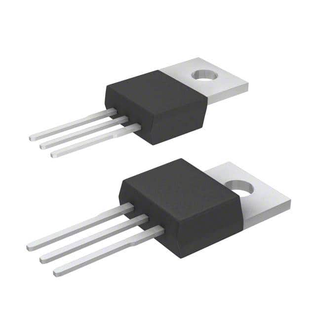
Diodes Incorporated AP1117T25L-U
- Part No.:
- AP1117T25L-U
- Manufacturer:
- Diodes Incorporated
- Package:
- TO-220-3
- Datasheet:
-
AP1117T25L-U.pdf
- Description:
- IC REG LDO 1.0A 2.5V TO220-3
- Quantity:
- Payment:

- Shipping:

Inventory:514
Please send an inquiry. Send us your inquiry, and we will respond immediately.
Product details
Overview
AP1117T25L-U from Diodes Incorporated is a 1A low-dropout linear regulator with fixed 2.5V output, SOT223 package, 1.4V max dropout at full load, ±2% output voltage accuracy, and integrated thermal shutdown. It delivers stable 2.5V supply for logic circuits, USB peripherals, and embedded microcontroller I/O rails in industrial and commercial systems.
For engineers reviewing the AP1117T25L-U datasheet, AP1117T25L-U pinout, AP1117T25L-U application, or AP1117T25L-U equivalent, key selection criteria include dropout voltage under 1A load, thermal resistance (θJA = 107°C/W), minimum required output capacitance (4.7µF ceramic), and fixed-output configuration eliminating external feedback resistors.
Technical Context
The AP1117T25L-U implements a PNP-based LDO architecture with internal reference (1.25V), error amplifier, and pass transistor. Its fixed 2.5V output is trimmed at wafer test, eliminating external resistor networks and reducing layout sensitivity to trace parasitics.
It features fast transient response due to optimized internal compensation, supports input voltages from 4.0V to 18V, and maintains regulation down to 1.3V headroom (VIN ≥ VOUT + 1.3V). Thermal shutdown activates at ~150°C junction temperature, with automatic recovery upon cooling.
Key Specifications
| Parameter | Value and Actual Design Meaning |
|---|---|
| Output Voltage | Fixed 2.500V ±2% (2.45–2.55V) at 10mA, ensuring compatibility with 2.5V logic families and ADC reference inputs. |
| Max Dropout Voltage | 1.4V at 1A load (ΔV = VIN – VOUT), enabling operation from 3.9V input while sustaining 2.5V output. |
| Output Current | 1A continuous (with adequate PCB copper heatsinking), sufficient for powering multiple ICs on a local rail. |
| Line Regulation | 0.2% over VIN range (4.8V–12V), limiting output drift to ±5mV across input variation. |
| Load Regulation | 20–25mV from 0–1A load, maintaining tight voltage control during dynamic current changes. |
| Thermal Resistance θJA | 107°C/W (SOT223 on 2oz FR-4, 5mm×5mm pad), requiring derating above 85°C ambient for full 1A operation. |
| Ripple Rejection | 60–70dB at 180Hz, suppressing low-frequency noise from switching pre-regulators or noisy DC sources. |
Pinout & Package
SOT223-3 package with exposed thermal tab electrically connected to VOUT; requires soldered thermal pad for rated power dissipation. Pin 1 (Adj/GND) is grounded for fixed-mode operation; Pin 2 (VOUT) supplies regulated 2.5V; Pin 3 (VIN) accepts 4.0–18V input.
| Pin/Terminal | Circuit Role | Design Meaning |
|---|---|---|
| 1 (Adj/GND) | Ground reference terminal | Internally tied to GND in fixed-output variants; must be connected to system ground to complete regulation loop. |
| 2 (VOUT) | Regulated output node | Delivers 2.5V; tab is electrically connected to this pin-PCB thermal pad must be grounded to system GND plane. |
| 3 (VIN) | Unregulated input supply | Accepts 4.0–18V; requires ≥4.7µF low-ESR capacitor (≤0.5Ω) placed within 10mm for stability. |
Key Features
| Feature | Design Value |
|---|---|
| Fixed 2.5V output | Eliminates external resistor divider, reducing BOM count, layout area, and voltage-setting errors. |
| 1.4V max dropout @ 1A | Enables use with low-headroom sources (e.g., 3.3V buck converter + LDO post-regulation) without sacrificing output stability. |
| Built-in thermal shutdown | Protects against sustained overload or poor heatsinking by disabling output above ~150°C junction temperature. |
| Stable with MLCC capacitors | Supports 4.7µF X7R ceramic output caps (not Y5V), simplifying decoupling and reducing board space vs. tantalum/aluminum. |
| Lead-free & Halogen-free | RoHS-compliant (Pb-free, Br/Sb <900ppm), meeting environmental requirements for industrial and consumer deployments. |
Applications
| USB Peripheral Power | Microcontroller I/O Rail |
|---|---|
Use Scenario: Powering USB 2.0 hubs, HID devices, or serial adapters requiring clean 2.5V for PHY or level-shifting circuitry. IC Role / Device Role / Timing Role: Primary 2.5V LDO supplying VDD_IO of USB transceivers and interface buffers. Use Value: Low dropout ensures regulation from 3.3V upstream rail; 70dB ripple rejection prevents USB packet errors from switching noise. |
Use Scenario: Providing dedicated 2.5V supply to GPIO banks, ADC reference inputs, or analog comparators in MCU-based edge nodes. IC Role / Device Role / Timing Role: Local point-of-load regulator isolating sensitive analog/digital I/O from main system rail noise. Use Value: Tight load regulation (±25mV) maintains ADC accuracy across 0–1A load swings; fast transient response prevents brownout during burst I/O activity. |
| VGA Card Logic Supply | Industrial Sensor Interface |
Use Scenario: Delivering stable 2.5V to video DACs, timing controllers, or memory buffers on legacy VGA graphics cards. IC Role / Device Role / Timing Role: Fixed-output LDO replacing adjustable regulators to simplify design and improve yield in high-volume add-in cards. Use Value: Factory-trimmed 2.5V eliminates calibration steps; SOT223 thermal pad enables conduction cooling in confined card slots. |
Use Scenario: Powering 2.5V-output analog sensors (e.g., pressure transducers, RTD interfaces) in factory automation PLC modules. IC Role / Device Role / Timing Role: Precision local regulator ensuring sensor excitation and signal chain bias remain within spec across temperature (-40°C to +85°C). Use Value: ±0.5% temperature stability and low thermal drift preserve sensor accuracy; industrial-grade temp range (-40°C to +125°C) matches sensor operating envelope. |
Equivalent & Alternatives
The following parts are listed as comparable options for similar fixed-output LDO applications.
| Alternative Part | Technical Difference | Application Difference | Selection Advice |
|---|---|---|---|
| AP1117T33L-U | Fixed 3.3V output; identical dropout, thermal, and package specs. | Used where host SoC or peripheral requires 3.3V I/O-not compatible with 2.5V logic interfaces. | Select only if target voltage matches system rail; no electrical redesign needed beyond input/output cap verification. |
| TLV1117-25CDCYR | TI part with 1.2V dropout (vs. 1.4V), higher PSRR (75dB), but 800mA max current and different pinout (VOUT/VIN/GND). | Requires PCB layout change; suitable for space-constrained designs needing lower dropout or higher noise immunity. | Choose when >200mA headroom is available and thermal margin allows lower θJA; verify pin compatibility before layout reuse. |
Compared with AP1117T25L-U, AP1117T33L-U offers identical performance at 3.3V but cannot replace 2.5V rails, while TLV1117-25CDCYR provides better dropout and PSRR but demands layout revision and derates to 800mA-making AP1117T25L-U optimal for cost-sensitive, volume 2.5V LDO applications with proven thermal design.
Availability
AP1117T25L-U is available at Aetrix Electronics and suitable for USB peripheral power, microcontroller I/O rails, VGA card logic supplies, and industrial sensor interfaces requiring stable component supply and long-term manufacturability.
Supply support for AP1117T25L-U includes scheduled delivery planning, volume procurement assistance, BOM continuity management, traceable sourcing, and lifecycle availability coordination for OEM customers, industrial embedded developers, connected-device designers, and electronics production programs.
Manufacturer
Diodes Incorporated is a global manufacturer of discrete semiconductors and analog ICs, specializing in high-reliability power management, signal integrity, and protection solutions for industrial, computing, and consumer markets.
The AP1117 series targets cost-effective, thermally robust LDO regulation for legacy and new designs where simplicity, fixed output, and wide input range are prioritized over ultra-low quiescent current or programmability.
FAQ
What is the minimum input voltage required for AP1117T25L-U to regulate at full 1A load?
The AP1117T25L-U requires VIN ≥ VOUT + 1.4V = 3.9V to maintain regulation at 1A load, per guaranteed maximum dropout voltage. At lower input voltages, output drops below 2.5V or regulation fails entirely. Input must also stay within absolute max rating of 18V.
Can AP1117T25L-U be used with ceramic output capacitors?
Yes-AP1117T25L-U is explicitly qualified for stability with 4.7µF X7R ceramic capacitors (ESR ≤ 0.5Ω). Y5V dielectrics are prohibited due to capacitance loss at bias/temperature; aluminum electrolytics require ≥47µF and benefit from parallel 1µF MLCC.
Is AP1117T25L-U pin-compatible with other 1117-family regulators?
Yes-AP1117T25L-U uses standard SOT223-3 pinout (VIN-VOUT-GND), matching industry 1117 regulators including LM1117, TLV1117, and AZ1117. However, thermal performance and dropout specs differ; verify θJA and load transient behavior in final layout.
Does AP1117T25L-U support operation below 0°C?
Yes-the AP1117I variant (industrial grade) supports -40°C to +125°C junction temperature. For sub-zero operation, Diodes recommends 22µF input/output capacitors (per Note 11) and verifying thermal design to prevent cold-temperature ESR rise from destabilizing regulation.
AP1117T25L-U Specifications
- Product attributes
- Attribute value
- Manufacturer:
- Diodes Incorporated
- Series:
- -
- Package/Case:
- TO-220-3
- Packaging:
- Tube
- Product Status:
- Active
- Output Configuration:
- Positive
- Output Type:
- Fixed
- Number of Regulators:
- 1
- Voltage - Input (Max):
- 18V
- Voltage - Output (Min/Fixed):
- 2.5V
- Voltage - Output (Max):
- -
- Voltage Dropout (Max):
- 1.4V @ 1A
- Current - Output:
- 1A
- Current - Quiescent (Iq):
- 10 mA
- Current - Supply (Max):
- -
- PSRR:
- 60dB (180Hz)
- Control Features:
- -
- Protection Features:
- Over Current, Over Temperature
- Operating Temperature:
- 0°C ~ 125°C (TJ)
- Grade:
- -
- Qualification:
- -
- Mounting Type:
- Through Hole
- Supplier Device Package:
- TO-220-3
AP1117T25L-U FAQ
1.How can I place an order for AP1117T25L-U through Aetrix?
Please submit a Request for Quotation (RFQ) for AP1117T25L-U on Aetrix. Our sales agent will provide a competitive quotation and guide you through the order confirmation once you accept the terms.
2.Are the price and stock information for AP1117T25L-U reliable?
The price and inventory of AP1117T25L-U are updated periodically and may fluctuate due to market conditions. Stock and pricing data are typically refreshed every 24 hours. Quotation validity for AP1117T25L-U is usually 5 days.
3.What payment methods are accepted for AP1117T25L-U?
We accept Wire Transfer, PayPal, Credit Card, Western Union, MoneyGram, and Escrow for AP1117T25L-U transactions.
Note: Certain payment methods may incur a processing fee.
4.How is shipping managed for AP1117T25L-U?
AP1117T25L-U orders can be shipped via leading logistics carriers, including DHL, UPS, FedEx, TNT, or Registered Mail.
Once your AP1117T25L-U order is processed, you will receive an email with the shipment details and tracking number.
Note: Tracking information may take up to 24 hours to appear. Express delivery typically takes 3–5 business days.
5.How can I obtain technical support or documentation for AP1117T25L-U?
For technical support, including AP1117T25L-U datasheets, pinout diagrams, or application guidance, please contact our engineering support team. They can provide detailed documentation and assistance for your AP1117T25L-U requirements.
6.How does Aetrix verify that AP1117T25L-U is sourced from the original manufacturer or authorized distributors?
All AP1117T25L-U products on Aetrix are procured from qualified distributors and authorized channels. Our dedicated quality assurance team conducts strict verification, including traceability checks and, if necessary, third-party testing. This ensures that AP1117T25L-U meets industry standards.
7.What is the process for return or replacement of AP1117T25L-U?
All AP1117T25L-U units undergo pre-shipment inspection (PSI). If there is an issue with AP1117T25L-U, returns or replacements are accepted under the following conditions:
1.Quantity discrepancies, incorrect items, or visible external defects (such as breakage or corrosion), acknowledged by Aetrix.
2.The issue is reported within 90 days of delivery.
3.The AP1117T25L-U part is unused and in its original packaging.
Return procedure for AP1117T25L-U:
1.Submit a request within 90 days.
2.Obtain a Return Material Authorization (RMA) from Aetrix.
AP1117T25L-U Tags

-
MIC5504-1.8YM5-TR
Microchip Technology

-
MIC5504-3.3YM5-TR
Microchip Technology

-
MIC5365-3.0YC5-TR
Microchip Technology

-
MIC5365-1.8YC5-TR
Microchip Technology

-
MIC5365-2.5YC5-TR
Microchip Technology

-
MIC5365-3.3YC5-TR
Microchip Technology

-
MIC5365-3.3YD5-TR
Microchip Technology

-
MIC5317-3.3YM5-TR
Microchip Technology

-
TLV1117LV33DCYR
Texas Instruments

-
MIC5317-3.3YMT-TZ
Microchip Technology

-
MIC5528-3.3YMT-TR
Microchip Technology

-
TLV75801PDRVR
Texas Instruments
Tech Hub

Comparator circuit design covering voltage thresholds, input limits, open-collector outputs, LM393 wiring, op-amp differences, hysteresis, timing, window detection and practical fault diagnosis.
Schmitt triggers use separate rising and falling thresholds to stabilize slow or noisy signals. This guide covers hysteresis, 74HC14 and 74HCT14 selection, comparator calculations, RC oscillators and p…
Counterfeit components can hide behind convincing markings and passing basic function tests. This engineering reference covers source traceability, external inspection, X-ray, XRF, electrical testing, …
A practical engineering and sourcing framework covering lifecycle verification, lifetime-buy calculations, replacement qualification, supplier checks and counterfeit-risk controls.
TTL and CMOS logic families differ in thresholds, loading, output drive, power and timing. This engineering guide compares 74HC and 74HCT, calculates noise margins and checks 3.3 V/5 V compatibility.
A practical engineering guide to 3.3V and 5V logic compatibility, input thresholds, resistor dividers, translator ICs, MOSFET level shifting, I2C pull-ups, timing limits and power-sequencing risks.
The 74HC595 uses push-pull logic outputs, while the TPIC6B595 uses 50 V open-drain DMOS sinks for higher-power loads. This guide compares timing, current limits, 3.3 V interfacing, load wiring, thermal…
The 74HC595 converts serial data into eight stable parallel outputs. This guide covers pin functions, shift and storage timing, OE and MR behavior, drive-current limits, cascading, voltage compatibilit…
A technical comparison of level-sensitive latches and edge-triggered flip-flops, covering timing windows, setup and hold limits, master–slave operation, time borrowing, race-through, HDL inference and…
A D latch stores one bit while Enable controls when data can pass. This reference covers gate-level operation, truth tables, transparency, setup and hold timing, LE versus OE, common ICs and practical …