
 My Inquiry
 My Account


Silicon Labs C8051F321R
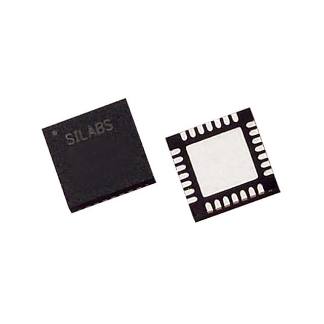
- Part No.:
- C8051F321R
- Manufacturer:
- Silicon Labs
- Category:
- Microcontrollers
- Package:
- 28-VFQFN Exposed Pad
- Datasheet:
-
 C8051F321R.pdf
- Description:
- IC MCU 8BIT 16KB FLASH 28MLP
- Quantity:
- Payment:

- Shipping:

Inventory:4,454
Please send an inquiry. Send us your inquiry, and we will respond immediately.
Product details
Overview
C8051F321R from Silicon Laboratories is a fully integrated 8051-based microcontroller with on-chip Full Speed USB 2.0 controller, 16 kB ISP flash, 2304 B RAM, 10-bit 200 ksps ADC, and precision internal oscillator (0.25% accuracy with clock recovery). It operates from 4.0–5.25 V and supports -40°C to +85°C industrial temperature range in a 28-pin MLP package.
For engineers reviewing the C8051F321R datasheet, C8051F321R pinout, C8051F321R application, or C8051F321R equivalent, key selection considerations include USB clock recovery without external crystal, 5 V-tolerant I/O, on-chip debug via C2 interface, and real-time clock capability using PCA or timer with external clock source.
Technical Context
The C8051F321R implements a pipelined CIP-51 core delivering up to 25 MIPS at 25 MHz, with expanded interrupt handling (16 sources) and memory-mapped peripherals accessed via priority crossbar. Its USB subsystem complies with USB 2.0, supports eight flexible endpoints, and integrates transceiver and 1 kB buffer - eliminating external resistors and crystal for full-speed operation.
Analog functionality includes a 10-bit ADC with up to 17 single-ended or 13 differential inputs, programmable VREF source (external, internal, or VDD), built-in temperature sensor, and two comparators with reset capability. Digital peripherals comprise hardware-enhanced SPI, SMBus, UART, four 16-bit timers, and a 16-bit PCA with five capture/compare modules.
Key Specifications
| Parameter | Value and Actual Design Meaning |
|---|---|
| Core | CIP-51 8051-compatible, pipelined, 25 MIPS @ 25 MHz |
| USB Interface | Full Speed (12 Mbps) & Low Speed (1.5 Mbps); integrated transceiver & clock recovery |
| ADC | 10-bit, 200 ksps max; 17 SE / 13 diff inputs; internal temp sensor & VREF options |
| Memory | 16 kB ISP flash (512-byte sectors); 2304 B RAM (1k + 256 + 1k USB FIFO) |
| I/O | 21 GPIO pins; all 5 V tolerant with high sink current |
| Oscillator | Internal precision oscillator (0.25% accuracy w/ USB clock recovery); supports external crystal/RC/C/clock |
| Package | 28-pin MLP (5 × 5 mm, 0.5 mm pitch), RoHS-compliant |
Pinout & Package
28-pin MLP (5 × 5 mm, 0.5 mm pitch) package with exposed thermal pad; designed for compact USB-enabled embedded applications requiring minimal board area and no external crystal.
| Pin/Terminal | Circuit Role | Design Meaning |
|---|---|---|
| VDD | Power supply | 4.0–5.25 V main supply; powers core, analog, and digital blocks |
| GND | Ground reference | Digital and analog ground common connection point |
| USB+ / USB− | USB differential data lines | Direct connection to USB host/device; no external termination required |
| P0.0–P0.7 | Port 0 I/O | 8-bit bidirectional port; all pins 5 V tolerant; configurable via crossbar |
| P1.0–P1.7 | Port 1 I/O | 8-bit bidirectional port; includes C2CK/C2D debug pins; 5 V tolerant |
| P2.0–P2.4 | Port 2 I/O | 5-bit bidirectional port; supports analog input channels for ADC0 |
| XTAL1 / XTAL2 | External oscillator inputs | Optional crystal/RC connection; not required due to integrated clock recovery |
| VREF | Analog reference input | Selectable ADC reference source: external pin, internal 2.4 V, or VDD |
| TEMP | Temperature sensor output | Internal diode-connected transistor output for on-chip temperature measurement |
Key Features
| Feature | Design Value |
|---|---|
| USB clock recovery | Eliminates need for external crystal or oscillator in USB designs, reducing BOM cost and PCB footprint |
| On-chip debug via C2 interface | Enables non-intrusive in-system debugging with breakpoints, register/memory inspection, and single-stepping - no emulator required |
| Configurable analog multiplexer | Supports up to 17 single-ended or 13 differential ADC inputs with flexible channel routing and window compare detection |
| Real-time clock (RTC) mode | Uses external 32.768 kHz crystal with PCA or Timer to implement low-power RTC without dedicated RTC peripheral |
| 5 V-tolerant I/O | Allows direct interfacing with legacy 5 V logic systems without level-shifting circuitry |
Applications
| USB Human Interface Device (HID) | Industrial Sensor Node |
|---|---|
Use Scenario: Compact HID device such as USB keyboard, mouse, or custom control panel with local processing and USB reporting. IC Role / Device Role / Timing Role: Primary MCU executing HID protocol stack, managing button/encoder inputs, and performing USB enumeration and data transfer. Use Value: Integrated USB controller and clock recovery enable single-chip USB connectivity without external PHY or crystal - reducing component count and layout complexity. | Use Scenario: Remote environmental monitoring node measuring temperature, voltage, or analog sensor outputs and transmitting data over USB. IC Role / Device Role / Timing Role: Signal acquisition MCU with 10-bit ADC, temperature sensor, and USB interface for direct PC connection and firmware updates. Use Value: On-chip 10-bit ADC with programmable VREF and internal temperature sensor allows accurate analog sensing without external signal conditioning components. |
| Programmable Logic Controller (PLC) I/O Module | USB Firmware Upgrade Adapter |
Use Scenario: DIN-rail mounted I/O expansion module converting discrete 5 V signals to USB for host supervision and configuration. IC Role / Device Role / Timing Role: Industrial-grade interface MCU handling opto-isolated inputs/outputs and bridging to USB host via CDC or vendor-specific class. Use Value: 5 V-tolerant I/O and industrial temperature range (-40°C to +85°C) ensure reliable operation in harsh factory environments. | Use Scenario: Field-service tool that reprograms legacy embedded devices via UART or SPI while presenting as a USB mass storage or CDC device to host PC. IC Role / Device Role / Timing Role: USB-to-serial bridge with in-system flash programming capability and secure bootloader support. Use Value: 16 kB ISP flash and robust C2 debug interface allow field-upgradable firmware and secure bootloader implementation without JTAG hardware. |
Equivalent & Alternatives
The following parts are listed as comparable options for similar USB-enabled 8051 microcontroller applications.
| Alternative Part | Technical Difference | Application Difference | Selection Advice |
|---|---|---|---|
| C8051F340 | 32-pin LQFP; 64 kB flash; 4352 B RAM; same USB/ADC/peripheral set; higher memory and I/O count | Preferred for designs needing more flash, RAM, or GPIO; requires larger PCB footprint and external crystal for USB | Select when scaling firmware complexity or I/O requirements beyond C8051F321R capacity |
| CP2102N-A02-GM | Dedicated USB-to-UART bridge IC; no MCU core, flash, or ADC; smaller 24-QFN package; fixed function | Suitable only for simple serial bridging; cannot execute custom firmware or perform analog acquisition | Choose only for pure USB-UART conversion where local processing or analog sensing is unnecessary |
Compared with C8051F321R, C8051F340 offers greater memory and I/O scalability but lacks integrated USB clock recovery, while CP2102N-A02-GM provides lower-cost serial bridging without programmability or analog capability - making C8051F321R optimal for compact, self-contained USB MCU applications requiring mixed-signal integration.
Availability
C8051F321R is available at Aetrix Electronics and suitable for USB HID devices, industrial sensor nodes, PLC I/O modules, and firmware upgrade adapters requiring stable component supply and long-term industrial availability.
Supply support for C8051F321R includes scheduled delivery planning, volume procurement assistance, BOM continuity management, traceable sourcing, and lifecycle availability coordination for OEM customers, industrial embedded developers, connected-device designers, and electronics production programs.
Manufacturer
Silicon Laboratories is a fabless semiconductor company specializing in mixed-signal ICs for timing, wireless, MCU, and sensor applications, with emphasis on integration and system-level optimization.
The C8051F32x family was designed to deliver USB-enabled 8051 performance in minimal footprint, targeting cost-sensitive, space-constrained embedded systems requiring native USB connectivity and analog sensing.
FAQ
Does the C8051F321R require an external crystal for USB operation?
No, the C8051F321R integrates a USB clock recovery circuit that enables Full Speed (12 Mbps) and Low Speed (1.5 Mbps) USB operation without any external crystal or oscillator. This eliminates BOM cost and layout complexity associated with external timing components while maintaining USB specification compliance. The internal oscillator achieves 0.25% accuracy when clock recovery is enabled, ensuring reliable USB communication for the C8051F321R.
What is the maximum sampling rate of the ADC in the C8051F321R?
The C8051F321R features a 10-bit successive-approximation ADC (ADC0) with a maximum throughput of 200 ksps (kilo-samples per second) under optimal conditions - including appropriate VREF stability, input settling time, and conversion mode configuration. This rate applies to single-ended conversions with internal reference and minimal channel switching; actual sustained rate depends on system clock, analog input impedance, and software overhead in the C8051F321R application.
How many I/O pins does the C8051F321R provide, and are they 5 V tolerant?
The C8051F321R provides 21 general-purpose I/O pins (P0.0–P0.7, P1.0–P1.7, P2.0–P2.4, plus P3.0/P3.1 shared with USB) - all configured as 5 V tolerant with high sink current capability. This allows direct interfacing with standard 5 V logic families without external level shifters, simplifying design in mixed-voltage systems and enhancing robustness in industrial environments where the C8051F321R is commonly deployed.
Can the C8051F321R be debugged in-system without an emulator?
Yes, the C8051F321R includes on-chip debug circuitry accessible via the 2-wire C2 interface (C2CK and C2D pins), enabling full-speed, non-intrusive in-system debugging. Engineers can set breakpoints, single-step code, and inspect/modify registers and memory directly on the target hardware - eliminating the need for ICE chips, target pods, or sockets. This capability is fully supported in Simplicity Studio for the C8051F321R.
What packaging options are available for the C8051F321R?
The C8051F321R is exclusively offered in a 28-pin MLP (Micro Lead Frame Package) with 5 × 5 mm body size and 0.5 mm pin pitch, featuring an exposed thermal pad for enhanced power dissipation. This compact, near-chip-scale package supports fine-pitch surface-mount assembly and is optimized for space-constrained USB peripheral designs where the C8051F321R delivers integrated functionality without external components.
C8051F321R Specifications
- Product attributes
- Attribute value
- Manufacturer:
- Silicon Labs
- Package/Case:
- 28-VFQFN Exposed Pad
- Series:
- C8051F32x
- Packaging:
- Tape & Reel (TR)
- Product Status:
- Obsolete
- Programmable:
- Not Verified
- Core Processor:
- 8051
- Core Size:
- 8-Bit
- Speed:
- 25MHz
- Connectivity:
- SMBus (2-Wire/I2C), SPI, UART/USART, USB
- Peripherals:
- Brown-out Detect/Reset, POR, PWM, Temp Sensor, WDT
- Number of I/O:
- 21
- Program Memory Size:
- 16KB (16K x 8)
- Program Memory Type:
- FLASH
- EEPROM Size:
- -
- RAM Size:
- 2.25K x 8
- Voltage - Supply (Vcc/Vdd):
- 2.7V ~ 3.6V
- Data Converters:
- A/D 13x10b
- Oscillator Type:
- Internal
- Operating Temperature:
- -40°C ~ 85°C (TA)
- Grade:
- -
- Qualification:
- -
- Mounting Type:
- Surface Mount
- Supplier Device Package:
C8051F321R FAQ
1.How can I place an order for C8051F321R through Aetrix?
Please submit a Request for Quotation (RFQ) for C8051F321R on Aetrix. Our sales agent will provide a competitive quotation and guide you through the order confirmation once you accept the terms.
2.Are the price and stock information for C8051F321R reliable?
The price and inventory of C8051F321R are updated periodically and may fluctuate due to market conditions. Stock and pricing data are typically refreshed every 24 hours. Quotation validity for C8051F321R is usually 5 days.
3.What payment methods are accepted for C8051F321R?
We accept Wire Transfer, PayPal, Credit Card, Western Union, MoneyGram, and Escrow for C8051F321R transactions.
Note: Certain payment methods may incur a processing fee.
4.How is shipping managed for C8051F321R?
C8051F321R orders can be shipped via leading logistics carriers, including DHL, UPS, FedEx, TNT, or Registered Mail.
Once your C8051F321R order is processed, you will receive an email with the shipment details and tracking number.
Note: Tracking information may take up to 24 hours to appear. Express delivery typically takes 3–5 business days.
5.How can I obtain technical support or documentation for C8051F321R?
For technical support, including C8051F321R datasheets, pinout diagrams, or application guidance, please contact our engineering support team. They can provide detailed documentation and assistance for your C8051F321R requirements.
6.How does Aetrix verify that C8051F321R is sourced from the original manufacturer or authorized distributors?
All C8051F321R products on Aetrix are procured from qualified distributors and authorized channels. Our dedicated quality assurance team conducts strict verification, including traceability checks and, if necessary, third-party testing. This ensures that C8051F321R meets industry standards.
7.What is the process for return or replacement of C8051F321R?
All C8051F321R units undergo pre-shipment inspection (PSI). If there is an issue with C8051F321R, returns or replacements are accepted under the following conditions:
1.Quantity discrepancies, incorrect items, or visible external defects (such as breakage or corrosion), acknowledged by Aetrix.
2.The issue is reported within 90 days of delivery.
3.The C8051F321R part is unused and in its original packaging.
Return procedure for C8051F321R:
1.Submit a request within 90 days.
2.Obtain a Return Material Authorization (RMA) from Aetrix.
C8051F321R Tags

-
ATTINY4-TSHR
Microchip Technology
-
ATTINY10-TSHR
Microchip Technology
-
ATTINY10-TS8R
Microchip Technology

-
ATTINY202-SSNR
Microchip Technology
-
ATTINY202-SSFR
Microchip Technology
-
ATTINY402-SSNR
Microchip Technology

-
PIC16F15213T-I/MF
Microchip Technology
-
PIC16F15213-E/MF
Microchip Technology

-
PIC10F200T-I/OT
Microchip Technology
-
ATTINY412-SSNR
Microchip Technology
-
PIC10F202T-I/OT
Microchip Technology

-
ATTINY404-SSNR
Microchip Technology
Tech Hub

Comparator circuit design covering voltage thresholds, input limits, open-collector outputs, LM393 wiring, op-amp differences, hysteresis, timing, window detection and practical fault diagnosis.
Schmitt triggers use separate rising and falling thresholds to stabilize slow or noisy signals. This guide covers hysteresis, 74HC14 and 74HCT14 selection, comparator calculations, RC oscillators and p…

Counterfeit components can hide behind convincing markings and passing basic function tests. This engineering reference covers source traceability, external inspection, X-ray, XRF, electrical testing, …

A practical engineering and sourcing framework covering lifecycle verification, lifetime-buy calculations, replacement qualification, supplier checks and counterfeit-risk controls.

TTL and CMOS logic families differ in thresholds, loading, output drive, power and timing. This engineering guide compares 74HC and 74HCT, calculates noise margins and checks 3.3 V/5 V compatibility.

A practical engineering guide to 3.3V and 5V logic compatibility, input thresholds, resistor dividers, translator ICs, MOSFET level shifting, I2C pull-ups, timing limits and power-sequencing risks.

The 74HC595 uses push-pull logic outputs, while the TPIC6B595 uses 50 V open-drain DMOS sinks for higher-power loads. This guide compares timing, current limits, 3.3 V interfacing, load wiring, thermal…

The 74HC595 converts serial data into eight stable parallel outputs. This guide covers pin functions, shift and storage timing, OE and MR behavior, drive-current limits, cascading, voltage compatibilit…

A technical comparison of level-sensitive latches and edge-triggered flip-flops, covering timing windows, setup and hold limits, master–slave operation, time borrowing, race-through, HDL inference and…

A D latch stores one bit while Enable controls when data can pass. This reference covers gate-level operation, truth tables, transparency, setup and hold timing, LE versus OE, common ICs and practical …


