Send an Inquiry

To receive a quote for your project, please fill in the following information, and we’ll get back to you promptly.

Name*
Company*
Email Address*
Phone/WhatsApp
Part Number*
Quantity*
Message
Submit Inventory List

Please fill in the following information, and we’ll get back to you promptly.

Name*
Company*
Email Address*
Phone/WhatsApp
Upload My List
Message

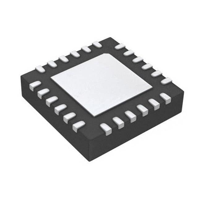
Silicon Labs C8051F557-IMR

Part No.:
C8051F557-IMR
Manufacturer:
Silicon Labs
Category:
Microcontrollers
Package:
24-WFQFN Exposed Pad
Datasheet:
AetrixC8051F557-IMR.pdf
Description:
IC MCU 8BIT 16KB FLASH 24QFN
Quantity:
Payment:
Payment
Shipping:
Shipping

Inventory:4,150

Please send an inquiry. Send us your inquiry, and we will respond immediately.

Part Number
Quantity*
Price
Name*
Company
Email*
Comments

Product details

Overview

C8051F557-IMR from Silicon Laboratories is an automotive-grade, mixed-signal ISP Flash MCU featuring a 50 MHz pipelined 8051 core, 12-bit ADC (200 ksps, 32-channel), CAN 2.0 controller with crystal-less operation, and LIN 2.1 support - deployed in engine control units and battery management systems requiring AEC-Q100 compliance.

For engineers reviewing the C8051F557-IMR datasheet, C8051F557-IMR pinout, C8051F557-IMR application, or C8051F557-IMR equivalent, key selection criteria include crystal-less CAN/LIN timing accuracy (±0.5% internal 24 MHz oscillator), 5 V-tolerant I/O count (18 pins), stop-mode current (1 µA), and QFN-24 package compatibility with automotive thermal and space constraints.

Technical Context

The C8051F557-IMR integrates a CIP-51 8051 core with dual clock domains: a high-accuracy 24 MHz internal oscillator for CAN/LIN synchronization and flexible external clock sources (crystal, RC, capacitor) for system timing. Its analog subsystem includes a single 12-bit ADC with programmable gain, temperature sensor, and two comparators with hysteresis and interrupt/reset capability.

Digital peripherals include hardware UART, SMBus, enhanced SPI, four 16-bit timers, a 16-bit PCA with six capture/compare modules, and a priority crossbar switch routing I/O to on-chip peripherals. All 18 port I/O pins are 5 V tolerant and configurable for analog/digital functions via dedicated SFRs.

Key Specifications

ParameterValue and Actual Design Meaning
CoreHigh-speed pipelined 8051 (CIP-51); executes 70% of instructions in 1–2 clocks → enables deterministic real-time response at 50 MIPS.
Flash Memory16 kB ISP flash in 512-byte sectors → supports field firmware updates without external programmer.
ADC Resolution & Speed12-bit SAR ADC, up to 200 ksps → resolves 0.24 mV per LSB at 2.5 V reference for precision sensor interfacing.
CAN InterfaceCAN 2.0B controller with crystal-less operation using internal 24 MHz ±0.5% oscillator → eliminates external crystal cost and board area in automotive nodes.
Supply & Power1.8–5.25 V operation; 19 mA typical @ 50 MHz, 1 µA stop mode → enables direct connection to 3.3 V or 5 V rails and ultra-low-power sleep states.
Temperature Range–40 °C to +125 °C, AEC-Q100 qualified → certified for under-hood automotive environments including powertrain and chassis modules.
I/O Count & Tolerance18 GPIO, all 5 V tolerant → simplifies interface with legacy 5 V sensors and actuators without level-shifting circuitry.

Pinout & Package

Package: 24-pin QFN (5 mm × 5 mm, 0.5 mm pitch), exposed thermal pad, RoHS-compliant, moisture sensitivity level 3.

Pin/TerminalCircuit RoleDesign Meaning
VDDPower supplyMain digital/analog supply rail (1.8–5.25 V); decoupling required per datasheet layout guidelines.
GNDGround referenceAnalog and digital ground common point; thermal pad must be soldered to PCB ground plane.
P0.0–P0.7Port 0 I/O8-bit bidirectional port; all pins 5 V tolerant and configurable as analog inputs or digital peripherals (UART, SPI, etc.).
P1.0–P1.7Port 1 I/O8-bit bidirectional port; includes CAN TX/RX, LIN TX/RX, and comparator inputs - routed via crossbar to selected peripherals.
P2.0–P2.3Port 2 I/O4-bit bidirectional port; supports ADC inputs, external interrupts, and timer/capture functions.
C2CK / C2DDebug interface2-wire C2 interface for non-intrusive in-system debug and flash programming - requires no emulator or target pod.
XTAL1 / XTAL2External oscillatorOptional crystal or RC input pins; not required for CAN/LIN when using internal 24 MHz oscillator.

Key Features

FeatureDesign Value
Crystal-less CAN/LIN timingInternal 24 MHz oscillator with ±0.5% accuracy over –40 to +125 °C ensures reliable bus communication without external crystal or trimming components.
Configurable analog multiplexer32-channel analog input selection for ADC0 allows dynamic routing of sensor signals (e.g., thermistors, pressure transducers) without external mux ICs.
Hardware-enhanced serial interfacesIndependent UART, SMBus, and enhanced SPI controllers with FIFO-like buffering reduce CPU overhead and improve deterministic latency in multi-node networks.
Low-power stop mode1 µA typical current draw with RAM retention and wake-up on external interrupt or comparator event enables long-duration battery-powered monitoring.
On-chip voltage regulator (REG0)Integrated LDO supplies core logic from VDD; supports stable operation across full input voltage range without external regulator.

Applications

Engine Control Unit (ECU)Battery Management System (BMS)

Use Scenario: Real-time acquisition of crankshaft position, throttle angle, and intake air temperature in gasoline/diesel engine control.

IC Role / Device Role / Timing Role: Central MCU executing closed-loop fuel injection and spark timing algorithms with sub-microsecond interrupt latency.

Use Value: Crystal-less CAN interface reduces BOM cost and improves EMI robustness; 12-bit ADC resolves sensor data with <1% total error over full automotive temperature range.

Use Scenario: Monitoring cell voltage, pack current, and temperature in 12–48 V EV/HEV battery packs.

IC Role / Device Role / Timing Role: Analog front-end processor and CAN gateway aggregating data from multiple analog sensors and relaying to main controller.

Use Value: 5 V-tolerant I/O directly interfaces with isolated ADCs and current shunt amplifiers; AEC-Q100 qualification ensures reliability in safety-critical energy storage applications.

Chassis Control ModuleIndustrial Motor Drive Controller

Use Scenario: ABS/ESC actuator control and wheel speed signal conditioning in vehicle stability systems.

IC Role / Device Role / Timing Role: Real-time PWM generation (via PCA) and analog feedback processing for solenoid valve drivers.

Use Value: Six PCA capture/compare modules enable simultaneous high-resolution PWM (11-bit) and encoder pulse counting - eliminating need for external timing ICs.

Use Scenario: Closed-loop speed/torque control of BLDC motors in factory automation equipment.

IC Role / Device Role / Timing Role: Sensor fusion hub combining Hall-effect encoder inputs, current sense ADC readings, and thermal protection signals.

Use Value: Internal temperature sensor provides on-die thermal monitoring for motor driver IC protection; LIN interface enables low-cost slave node communication in distributed drive architectures.

Equivalent & Alternatives

The following parts are listed as comparable options for similar mixed-signal MCU applications.

Alternative PartTechnical DifferenceApplication DifferenceSelection Advice
C8051F560-IM32-pin QFP/QFN package; 25 GPIO; 32 kB flash; same core/peripherals but higher I/O count and memory.Suitable for designs needing more analog inputs or expanded serial interface routing.Select C8051F560-IM when >18 I/O or >16 kB flash is required; pinout and footprint differ - PCB redesign needed.
SPC560B50L3Power Architecture core; 32-bit; 512 kB flash; integrated CAN FD and Ethernet; no integrated ADC.Targeted at higher-tier automotive ECUs requiring ASIL-B compliance and advanced networking.Choose SPC560B50L3 for next-generation platforms demanding functional safety certification and CAN FD bandwidth - not a drop-in replacement.

Compared with C8051F557-IMR, C8051F560-IM offers greater I/O and memory in a larger package, while SPC560B50L3 delivers higher compute performance and safety features at the cost of increased complexity and external analog signal conditioning requirements.

Availability

C8051F557-IMR is available at Aetrix Electronics and suitable for automotive engine control, battery management, chassis electronics, and industrial motor drive applications requiring stable component supply and AEC-Q100-qualified silicon.

Supply support for C8051F557-IMR includes scheduled delivery planning, volume procurement assistance, BOM continuity management, traceable sourcing, and lifecycle availability coordination for OEM customers, industrial embedded developers, connected-device designers, and electronics production programs.

Manufacturer

Silicon Laboratories is a fabless semiconductor company specializing in mixed-signal ICs for timing, MCU, wireless, and sensor applications, with deep expertise in high-precision oscillators and energy-efficient microcontrollers.

The C8051F55x family targets cost-sensitive, thermally constrained automotive and industrial embedded systems where crystal-less communication, analog integration, and AEC-Q100 reliability are mandatory design requirements.

FAQ

What is the maximum operating frequency and instruction throughput of the C8051F557-IMR?

The C8051F557-IMR operates at up to 50 MHz system clock frequency, delivering 50 MIPS throughput due to its pipelined CIP-51 8051 core architecture. It executes 70% of instructions in just one or two system clocks, enabling deterministic real-time response critical for automotive control loops. This performance is fully supported across the full –40 °C to +125 °C temperature range specified for the C8051F557-IMR.

Does the C8051F557-IMR require an external crystal for CAN or LIN communication?

No, the C8051F557-IMR does not require an external crystal for CAN or LIN communication. It features an internal 24 MHz oscillator with ±0.5% accuracy over –40 °C to +125 °C, explicitly qualified for crystal-less CAN 2.0 and LIN 2.1 operation per the official Silicon Labs datasheet. External crystals remain optional for alternate clock sources but are unnecessary for compliant bus timing in the C8051F557-IMR.

How many analog input channels does the 12-bit ADC support on the C8051F557-IMR?

The C8051F557-IMR's 12-bit ADC (ADC0) supports up to 32 external single-ended analog inputs, selectable via an on-chip analog multiplexer. This capability is fully implemented in the C8051F557-IMR variant and enables flexible sensor interfacing - such as temperature, pressure, or voltage monitoring - without external signal routing components.

What is the stop mode current consumption of the C8051F557-IMR, and what functionality remains active?

The C8051F557-IMR achieves a typical stop mode current of 1 µA while retaining full 2304-byte RAM contents and supporting wake-up via external interrupt, comparator output, or PCA event. This ultra-low-power state is validated across the full automotive temperature range and is a defined operational mode in the C8051F557-IMR datasheet for battery-backed or intermittent-sensing applications.

Is the C8051F557-IMR pin-compatible with other devices in the C8051F55x/56x/57x family?

No, the C8051F557-IMR is not pin-compatible with other variants in the C8051F55x/56x/57x family. It uses a 24-pin QFN package, whereas C8051F56x devices use 32-pin QFP/QFN and C8051F57x devices use 40-pin QFN. Pin assignments, I/O count, and peripheral mapping differ across packages - meaning each variant requires a unique PCB layout. The C8051F557-IMR pinout is documented in Figure 3.4 of its official datasheet.

C8051F557-IMR Specifications

Product attributes
Attribute value
Manufacturer:
Silicon Labs
Package/Case:
24-WFQFN Exposed Pad
Series:
C8051F55x
Packaging:
Tape & Reel (TR)
Product Status:
Obsolete
Programmable:
Not Verified
Core Processor:
8051
Core Size:
8-Bit
Speed:
50MHz
Connectivity:
SMBus (2-Wire/I2C), SPI, UART/USART
Peripherals:
POR, PWM, Temp Sensor, WDT
Number of I/O:
18
Program Memory Size:
16KB (16K x 8)
Program Memory Type:
FLASH
EEPROM Size:
-
RAM Size:
2.25K x 8
Voltage - Supply (Vcc/Vdd):
1.8V ~ 5.25V
Data Converters:
A/D 18x12b
Oscillator Type:
Internal
Operating Temperature:
-40°C ~ 125°C (TA)
Grade:
-
Qualification:
-
Mounting Type:
Surface Mount
Supplier Device Package:

C8051F557-IMR FAQ

1.How can I place an order for C8051F557-IMR through Aetrix?

Please submit a Request for Quotation (RFQ) for C8051F557-IMR on Aetrix. Our sales agent will provide a competitive quotation and guide you through the order confirmation once you accept the terms.

2.Are the price and stock information for C8051F557-IMR reliable?

The price and inventory of C8051F557-IMR are updated periodically and may fluctuate due to market conditions. Stock and pricing data are typically refreshed every 24 hours. Quotation validity for C8051F557-IMR is usually 5 days.

3.What payment methods are accepted for C8051F557-IMR?

We accept Wire Transfer, PayPal, Credit Card, Western Union, MoneyGram, and Escrow for C8051F557-IMR transactions.

Note: Certain payment methods may incur a processing fee.

4.How is shipping managed for C8051F557-IMR?

C8051F557-IMR orders can be shipped via leading logistics carriers, including DHL, UPS, FedEx, TNT, or Registered Mail.

Once your C8051F557-IMR order is processed, you will receive an email with the shipment details and tracking number.

Note: Tracking information may take up to 24 hours to appear. Express delivery typically takes 3–5 business days.

5.How can I obtain technical support or documentation for C8051F557-IMR?

For technical support, including C8051F557-IMR datasheets, pinout diagrams, or application guidance, please contact our engineering support team. They can provide detailed documentation and assistance for your C8051F557-IMR requirements.

6.How does Aetrix verify that C8051F557-IMR is sourced from the original manufacturer or authorized distributors?

All C8051F557-IMR products on Aetrix are procured from qualified distributors and authorized channels. Our dedicated quality assurance team conducts strict verification, including traceability checks and, if necessary, third-party testing. This ensures that C8051F557-IMR meets industry standards.

7.What is the process for return or replacement of C8051F557-IMR?

All C8051F557-IMR units undergo pre-shipment inspection (PSI). If there is an issue with C8051F557-IMR, returns or replacements are accepted under the following conditions:

1.Quantity discrepancies, incorrect items, or visible external defects (such as breakage or corrosion), acknowledged by Aetrix.

2.The issue is reported within 90 days of delivery.

3.The C8051F557-IMR part is unused and in its original packaging.

Return procedure for C8051F557-IMR:

1.Submit a request within 90 days.

2.Obtain a Return Material Authorization (RMA) from Aetrix.

C8051F557-IMR Tags

  • C8051F557-IMR
  • C8051F557-IMR PDF
  • C8051F557-IMR Datasheet
  • C8051F557-IMR Specifications
  • C8051F557-IMR Images
  • Silicon Labs
  • Silicon Labs C8051F557-IMR
  • Buy C8051F557-IMR
  • C8051F557-IMR Price
  • C8051F557-IMR Distributor
  • C8051F557-IMR Supplier
  • C8051F557-IMR Wholesale
Related Products
ATTINY4-TSHR
ATTINY4-TSHR

Microchip Technology

ATTINY10-TSHR
ATTINY10-TSHR

Microchip Technology

ATTINY10-TS8R
ATTINY10-TS8R

Microchip Technology

ATTINY202-SSNR
ATTINY202-SSNR

Microchip Technology

ATTINY202-SSFR
ATTINY202-SSFR

Microchip Technology

ATTINY402-SSNR
ATTINY402-SSNR

Microchip Technology

PIC16F15213T-I/MF
PIC16F15213T-I/MF

Microchip Technology

PIC16F15213-E/MF
PIC16F15213-E/MF

Microchip Technology

PIC10F200T-I/OT
PIC10F200T-I/OT

Microchip Technology

ATTINY412-SSNR
ATTINY412-SSNR

Microchip Technology

PIC10F202T-I/OT
PIC10F202T-I/OT

Microchip Technology

ATTINY404-SSNR
ATTINY404-SSNR

Microchip Technology

Tech Hub

Search

Search

PRODUCT

PRODUCT

PHONE

PHONE

USER

USER