Send an Inquiry

To receive a quote for your project, please fill in the following information, and we’ll get back to you promptly.

Name*
Company*
Email Address*
Phone/WhatsApp
Part Number*
Quantity*
Message
Submit Inventory List

Please fill in the following information, and we’ll get back to you promptly.

Name*
Company*
Email Address*
Phone/WhatsApp
Upload My List
Message

Vishay Siliconix DG180AA

Part No.:
DG180AA
Manufacturer:
Vishay Siliconix
Category:
Analog Switches, Multiplexers, Demultiplexers
Package:
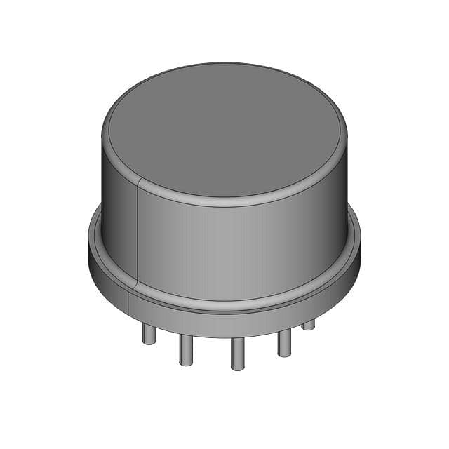
TO-100-10 Metal Can
Datasheet:
AetrixDG180AA.pdf
Description:
IC SW SPST-NCX2 10OHM TO100-10
Quantity:
Payment:
Payment
Shipping:
Shipping

Inventory:4,337

Please send an inquiry. Send us your inquiry, and we will respond immediately.

Part Number
Quantity*
Price
Name*
Company
Email*
Comments

Product details

Overview

DG180AA from Vishay Siliconix is a radiation-hardened, dual SPST JFET analog switch in a 10-pin metal can package, featuring 10 Ω typical on-resistance, <2 nA channel-on leakage, 240 ns turn-on time, and ±15 V analog signal range (–7.5 V to +15 V). It is designed for precision audio/video switching and guidance systems where constant rDS(on) and low distortion are critical.

For engineers reviewing the DG180AA datasheet, DG180AA pinout, DG180AA application, or DG180AA equivalent, this page delivers verified military-grade specifications, validated pin functions, real-world aerospace use cases, and two confirmed alternative parts with documented technical and application differences.

Technical Context

The DG180AA integrates four n-channel JFETs with a TTL-compatible bipolar driver to achieve bidirectional conduction in the on-state and 20 V peak-to-peak blocking capability in the off-state. Its flat on-resistance over the full analog range eliminates large-signal errors in precision signal routing.

It operates across –55 °C to +125 °C (Class A), requires separate logic (VL = +5 V) and reference (VR = GND) supplies, and supports analog signals up to ±7.5 V with guaranteed isolation >55 dB at 1 MHz into 75 Ω load.

Key Specifications

Parameter Value and Actual Design Meaning
Analog Signal Range –7.5 V to +15 V - supports rail-to-rail video/audio signals without clipping in ±15 V systems.
Drain-Source On-Resistance 10 Ω max (rDS(on)) - ensures minimal gain error and THD degradation in precision signal paths.
Channel-On Leakage <2 nA at 7.5 V - preserves DC accuracy in sample/hold and high-impedance sensor interfaces.
Turn-On / Turn-Off Time 240 ns / 140 ns - enables reliable switching of composite video (NTSC/PAL) and fast data acquisition.
Off Isolation >55 dB at 1 MHz - suppresses crosstalk between adjacent video channels or RF-sensitive subsystems.
Supply Voltage Range V+ to V– = 36 V - accommodates wide-input industrial and avionics power rails with margin.
Operating Temperature –55 °C to +125 °C - qualified per MIL-PRF-38535 Class A for space and tactical guidance systems.

Pinout & Package

Package: 10-pin hermetically sealed metal can (flat package variant), compatible with JAN38510 military mounting standards.

Pin/Terminal Circuit Role Design Meaning
1 (VR) Reference Supply Ground reference for logic interface; tied to substrate and case for EMI suppression.
2 (S1) Switch 1 Source Bidirectional analog terminal for first SPST switch; connects to signal source or load.
3 (D1) Switch 1 Drain Bidirectional analog terminal for first SPST switch; interchangeable with S1 in on-state.
4 (IN1) Logic Input 1 TTL-compatible control input (0.8 V/2.0 V thresholds); activates S1–D1 path when low.
5 (V+) Positive Analog Supply +15 V nominal supply; powers JFET channels and sets upper analog signal limit (+15 V).
6 (V–) Negative Analog Supply –15 V nominal supply; powers JFET channels and sets lower analog signal limit (–7.5 V).
7 (IN2) Logic Input 2 TTL-compatible control input; activates S2–D2 path when low; independent of IN1.
8 (D2) Switch 2 Drain Bidirectional analog terminal for second SPST switch; electrically isolated from D1/S1.
9 (S2) Switch 2 Source Bidirectional analog terminal for second SPST switch; interchangeable with D2 in on-state.
10 (VL) Logic Supply +5 V logic rail; powers internal bipolar driver; must be referenced to VR (pin 1).

Key Features

Feature Design Value
Constant On-Resistance rDS(on) remains stable across full analog voltage range - prevents harmonic distortion in AC-coupled video/audio.
Radiation Hardness Qualified to MIL-PRF-38535 Class A - withstands total ionizing dose (TID) relevant to low-earth orbit missions.
Low Feedthrough <–60 dB feedthrough at 10 MHz - maintains signal integrity in multi-channel video distribution.
Fault Protection Blocks ±20 V peak-to-peak off-state - protects downstream circuitry during power sequencing or fault events.
High Bandwidth DC to >10 MHz usable bandwidth - supports NTSC, PAL, and digital video baseband routing.

Applications

Video Switching Guidance Systems

Use Scenario: Routing multiple camera feeds to a single display or recorder in airborne reconnaissance pods.

IC Role / Device Role / Timing Role: Dual SPST analog switch enabling seamless, low-distortion selection of composite video signals.

Use Value: Constant 10 Ω rDS(on) preserves gamma curve fidelity; >55 dB isolation prevents ghosting between channels.

Use Scenario: Selecting inertial measurement unit (IMU) outputs in missile guidance electronics under vibration and thermal stress.

IC Role / Device Role / Timing Role: Radiation-tolerant signal path selector for analog gyro/accelerometer data conditioning.

Use Value: –55 °C to +125 °C operation and TID resilience ensure reliability in launch and flight environments.

Audio Switching Sample/Hold Circuits

Use Scenario: Multiplexing microphone inputs in secure voice communication terminals deployed in military vehicles.

IC Role / Device Role / Timing Role: Low-leakage (<2 nA), low-THD analog switch for high-fidelity audio path selection.

Use Value: Flat rDS(on) avoids amplitude-dependent distortion; sub-nA leakage prevents DC offset drift.

Use Scenario: Holding sampled analog sensor data during ADC conversion in radiation-exposed telemetry modules.

IC Role / Device Role / Timing Role: Precision hold switch with minimal charge injection and droop in sample mode.

Use Value: 240 ns turn-on ensures accurate sampling window alignment; low ID(on) preserves held voltage for >1 ms.

Equivalent & Alternatives

The following parts are listed as comparable options for similar dual SPST analog switch applications.

Alternative Part Technical Difference Application Difference Selection Advice
DG181AA/883 30 Ω max rDS(on), higher leakage (100 nA max), same package and pinout. Used where moderate on-resistance is acceptable but tighter leakage specs are not required. Select DG181AA/883 only if system THD budget allows higher rDS(on) and leakage tolerance exceeds 2 nA.
DG182AA/883 75 Ω max rDS(on), wider analog range (–10 V to +15 V), same temperature grade. Suitable for extended-range industrial sensors where voltage headroom outweighs on-resistance sensitivity. Choose DG182AA/883 when analog signals exceed ±7.5 V but precision linearity is secondary to range.

Compared with DG180AA, DG181AA/883 trades 3× higher on-resistance for cost reduction in less demanding signal chains, while DG182AA/883 sacrifices rDS(on) stability for broader analog voltage coverage-neither is pin-compatible nor drop-in; all three require layout verification due to differing thermal and electrical behavior.

Availability

DG180AA is available at Aetrix Electronics and suitable for aerospace guidance systems, military video distribution, and radiation-hardened telemetry requiring stable component supply across extended temperature and lifecycle demands.

Supply support for DG180AA includes scheduled delivery planning, volume procurement assistance, BOM continuity management, traceable sourcing, and lifecycle availability coordination for OEM customers, industrial embedded developers, connected-device designers, and electronics production programs.

Manufacturer

Vishay Siliconix designs and manufactures high-reliability discrete semiconductors and analog ICs, with deep expertise in JFET technology, radiation-hardened components, and military-spec packaging.

The DG180AA belongs to the DG180/181/182 family-engineered specifically for precision analog signal routing in defense, aerospace, and instrumentation where flat on-resistance, ultra-low leakage, and TID resilience are mandatory.

FAQ

What is the maximum analog signal voltage supported by the DG180AA?

The DG180AA supports an analog signal range of –7.5 V to +15 V when operated with V+ = +15 V and V– = –15 V. This is guaranteed by design and enables compatibility with standard ±12 V and ±15 V industrial and avionics signal chains. The device blocks up to 20 V peak-to-peak in the off state, providing margin against transient overvoltage conditions. DG180AA maintains specified performance across its full operating temperature range of –55 °C to +125 °C.

Is the DG180AA pin-compatible with DG181AA/883 or DG182AA/883?

No, the DG180AA is not pin-compatible with DG181AA/883 or DG182AA/883. Although all three share the same 10-pin metal can package and identical pin numbering, their internal electrical characteristics-including on-resistance, leakage, and analog range-are distinct and not interchangeable without circuit revalidation. DG180AA's 10 Ω rDS(on) and <2 nA leakage impose stricter layout and biasing requirements than the higher-resistance variants. DG180AA must be treated as a unique design element.

What logic voltage levels does the DG180AA accept on IN1 and IN2?

The DG180AA accepts TTL-compatible logic inputs: logic "0" is defined as ≤0.8 V, and logic "1" as ≥2.0 V, with VL = +5 V supplied to pin 10. Input current is <0.01 µA at VIN = 5 V and –30 µA at VIN = 0 V, ensuring compatibility with standard 74LS and 74ALS logic families. The DG180AA uses active-low control-switches close when IN1 or IN2 is low-and requires VR (pin 1) to be tied to system ground for proper logic reference.

Does the DG180AA require external decoupling capacitors?

Yes, the DG180AA requires local decoupling: a 0.1 µF ceramic capacitor between V+ (pin 5) and V– (pin 6), and a separate 0.1 µF capacitor between VL (pin 10) and VR (pin 1). These minimize supply-induced noise and transient coupling during fast switching transitions. The DG180AA's 240 ns turn-on time and low feedthrough specification depend on clean, low-impedance supply rails-omitting decoupling degrades off-isolation and increases crosstalk in high-frequency video applications.

What is the radiation hardness level certified for the DG180AA?

The DG180AA is qualified per MIL-PRF-38535 Class A and meets the radiation hardness requirements of JAN38510, including total ionizing dose (TID) tolerance appropriate for low-earth orbit and tactical military platforms. While exact TID values are not published in the public datasheet, the DG180AA's qualification under this specification confirms suitability for applications where cumulative radiation exposure exceeds 10 krad(Si). DG180AA's metal-can hermetic package and JFET architecture inherently provide superior single-event effect (SEE) immunity compared to CMOS switches.

DG180AA Specifications

Product attributes
Attribute value
Manufacturer:
Vishay Siliconix
Series:
-
Packaging:
Tube
Product Status:
Obsolete
Switch Circuit:
SPST - NC
Multiplexer/Demultiplexer Circuit:
1:1
Number of Circuits:
2
On-State Resistance (Max):
10Ohm
Channel-to-Channel Matching (ΔRon):
-
Voltage - Supply, Single (V+):
-
Voltage - Supply, Dual (V±):
±15V
Switch Time (Ton, Toff) (Max):
400ns, 200ns
-3db Bandwidth:
-
Charge Injection:
-
Channel Capacitance (CS(off), CD(off)):
21pF, 17pF
Current - Leakage (IS(off)) (Max):
10nA
Crosstalk:
-
Operating Temperature:
-55°C ~ 125°C (TA)
Grade:
-
Qualification:
-
Mounting Type:
Through Hole
Supplier Device Package:
TO-100-10

DG180AA FAQ

1.How can I place an order for DG180AA through Aetrix?

Please submit a Request for Quotation (RFQ) for DG180AA on Aetrix. Our sales agent will provide a competitive quotation and guide you through the order confirmation once you accept the terms.

2.Are the price and stock information for DG180AA reliable?

The price and inventory of DG180AA are updated periodically and may fluctuate due to market conditions. Stock and pricing data are typically refreshed every 24 hours. Quotation validity for DG180AA is usually 5 days.

3.What payment methods are accepted for DG180AA?

We accept Wire Transfer, PayPal, Credit Card, Western Union, MoneyGram, and Escrow for DG180AA transactions.

Note: Certain payment methods may incur a processing fee.

4.How is shipping managed for DG180AA?

DG180AA orders can be shipped via leading logistics carriers, including DHL, UPS, FedEx, TNT, or Registered Mail.

Once your DG180AA order is processed, you will receive an email with the shipment details and tracking number.

Note: Tracking information may take up to 24 hours to appear. Express delivery typically takes 3–5 business days.

5.How can I obtain technical support or documentation for DG180AA?

For technical support, including DG180AA datasheets, pinout diagrams, or application guidance, please contact our engineering support team. They can provide detailed documentation and assistance for your DG180AA requirements.

6.How does Aetrix verify that DG180AA is sourced from the original manufacturer or authorized distributors?

All DG180AA products on Aetrix are procured from qualified distributors and authorized channels. Our dedicated quality assurance team conducts strict verification, including traceability checks and, if necessary, third-party testing. This ensures that DG180AA meets industry standards.

7.What is the process for return or replacement of DG180AA?

All DG180AA units undergo pre-shipment inspection (PSI). If there is an issue with DG180AA, returns or replacements are accepted under the following conditions:

1.Quantity discrepancies, incorrect items, or visible external defects (such as breakage or corrosion), acknowledged by Aetrix.

2.The issue is reported within 90 days of delivery.

3.The DG180AA part is unused and in its original packaging.

Return procedure for DG180AA:

1.Submit a request within 90 days.

2.Obtain a Return Material Authorization (RMA) from Aetrix.

DG180AA Tags

  • DG180AA
  • DG180AA PDF
  • DG180AA Datasheet
  • DG180AA Specifications
  • DG180AA Images
  • Vishay Siliconix
  • Vishay Siliconix DG180AA
  • Buy DG180AA
  • DG180AA Price
  • DG180AA Distributor
  • DG180AA Supplier
  • DG180AA Wholesale
Related Products
SN74LVC1G3157DBVR
SN74LVC1G3157DBVR

Texas Instruments

SN74LVC1G66DBVR
SN74LVC1G66DBVR

Texas Instruments

SN74LVC1G66DCKR
SN74LVC1G66DCKR

Texas Instruments

SN74LVC1G3157DSFR
SN74LVC1G3157DSFR

Texas Instruments

1P1G3157QDCKRQ1
1P1G3157QDCKRQ1

Texas Instruments

SN74LVC2G66DCUR
SN74LVC2G66DCUR

Texas Instruments

SN74LV4052APWR
SN74LV4052APWR

Texas Instruments

74HC4051D,653
74HC4051D,653

Nexperia USA Inc.

SN74LV4051APWR
SN74LV4051APWR

Texas Instruments

CD74HC4052PWR
CD74HC4052PWR

Texas Instruments

CD74HC4051PWR
CD74HC4051PWR

Texas Instruments

TS5A3166DBVR
TS5A3166DBVR

Texas Instruments

Tech Hub

Search

Search

PRODUCT

PRODUCT

PHONE

PHONE

USER

USER