Send an Inquiry

To receive a quote for your project, please fill in the following information, and we’ll get back to you promptly.

Name*
Company*
Email Address*
Phone/WhatsApp
Part Number*
Quantity*
Message
Submit Inventory List

Please fill in the following information, and we’ll get back to you promptly.

Name*
Company*
Email Address*
Phone/WhatsApp
Upload My List
Message

Vishay Siliconix DG643DY-E3

Part No.:
DG643DY-E3
Manufacturer:
Vishay Siliconix
Category:
Analog Switches, Multiplexers, Demultiplexers
Package:
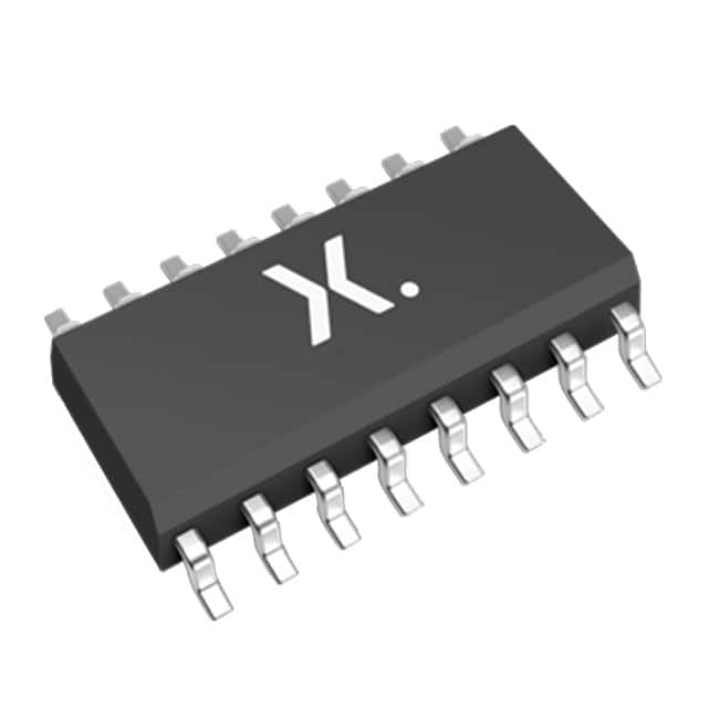
16-SOIC (0.154", 3.90mm Width)
Datasheet:
AetrixDG643DY-E3.pdf
Description:
IC SWITCH SPDT X 2 15OHM 16SOIC
Quantity:
Payment:
Payment
Shipping:
Shipping

Inventory:4,007

Please send an inquiry. Send us your inquiry, and we will respond immediately.

Part Number
Quantity*
Price
Name*
Company
Email*
Comments

Product details

Overview

DG643DY-E3 from Vishay Siliconix is a dual SPDT analog switch IC designed for high-fidelity video and RF signal routing in bidirectional wideband applications. It delivers 500 MHz bandwidth, 5 Ω typical RDS(on) (per channel), -87 dB crosstalk at 5 MHz, and operates from ±3 V to ±15 V dual supplies or single +15 V supply with V- grounded - enabling RGB switching and satellite receiver front-end signal selection.

For engineers reviewing the DG643DY-E3 datasheet, DG643DY-E3 pinout, DG643DY-E3 application, or DG643DY-E3 equivalent, key selection criteria include verified dual SPDT topology, SOIC-16 package compatibility, guaranteed -40 °C to +85 °C operation, low 40 pF off-state capacitance per channel, and TTL-compatible digital control with 50 ns tON.

Technical Context

The DG643DY-E3 implements two independent SPDT switches fabricated on Vishay's proprietary D/CMOS process, supporting true bidirectional analog signal flow with matched on-resistance (<1 Ω RDS(on) match) and negligible nonlinearity. Each switch handles ±5 V ac signals when biased with V+ = +12 V and V- = -5 V.

It integrates on-chip voltage regulation for stable TTL logic compatibility across full supply range, uses epitaxial isolation to prevent latchup, and features symmetrical source/drain terminals - eliminating channel polarity constraints in PCB layout and enabling flexible signal path routing in video multiplexers and programmable filters.

Key Specifications

Parameter Value and Actual Design Meaning
Switch Type Dual SPDT - provides two independent single-pole double-throw channels for signal routing redundancy or parallel path selection.
Bandwidth 500 MHz - supports full HD video (1080p60), UWB RF, and fast digital signal switching without attenuation roll-off.
RDS(on) 8 Ω max (typ. 5 Ω) - ensures low insertion loss <0.1 dB in 75 Ω video systems and minimal voltage drop under 75 mA continuous load.
Crosstalk -87 dB at 5 MHz - prevents interference between active and inactive channels in multi-source RGB or radar IF routing.
tON/tOFF 70 ns / 50 ns max - enables sub-100 ns channel switching for ATE test sequencing and real-time video source arbitration.
Supply Range V+ = -0.3 to +21 V, V- = -19 to +0.3 V - allows single-supply (V- = GND) or split-rail (-3 V/+15 V) operation for system-level power architecture flexibility.
Leakage Current <100 nA off-state - maintains signal integrity in high-impedance sensor interfaces and precision DC-coupled video paths.

Pinout & Package

Package: 16-pin narrow SOIC (MS-012), 3.9 mm × 9.9 mm body, 1.27 mm pitch, RoHS-compliant, moisture sensitivity level 1.

Pin/Terminal Circuit Role Design Meaning
1, 2, 3, 4 Source terminals (S1–S4) Bidirectional analog inputs/outputs; interchangeable with drains; support ±14 Vp-p signal swing when off.
5, 6, 13, 14 Drain terminals (D1–D4) Bidirectional analog inputs/outputs; electrically identical to sources; enable symmetric PCB trace routing.
7, 15 GND Analog/digital ground reference; must be star-connected and decoupled with 10 µF tantalum + 0.1 µF ceramic per supply rail.
8 V- Negative supply input; substrate connection; requires low-impedance decoupling to minimize noise coupling into analog channels.
16 V+ Positive supply input; powers internal regulator and switch core; accepts up to +21 V for extended dynamic range.
9, 10 Control inputs (IN1, IN2) TTL-compatible logic inputs (0.8 V/2.4 V thresholds); drive both SPDT switches simultaneously with shared enable logic.

Key Features

Feature Design Value
True bidirectional signal path Identical RDS(on), Coff, and leakage performance regardless of signal direction - eliminates routing constraints in differential or AC-coupled video designs.
On-chip TTL voltage regulator Maintains logic threshold stability across full V+/V- supply range (±3 V to ±15 V), removing need for external level shifters in mixed-voltage systems.
Epitaxial latchup protection Guarantees immunity to destructive latchup under transient overvoltage or ESD events - critical for field-deployed radar and satellite receivers.
Low charge injection (−19 pC) Minimizes voltage glitch on sampled-hold nodes and CCD output lines, preserving DC accuracy in precision imaging front-ends.
Matched channel timing ΔtON/ΔtOFF < 5 ns between dual SPDT channels - ensures synchronous switching in balanced IF signal paths and phase-coherent filter banks.

Applications

RGB Video Multiplexer Satellite IF Signal Selector

Use Scenario: Routing three independent RGB video streams from graphics processors to a single display controller with seamless source switching.

IC Role / Device Role / Timing Role: Dual SPDT configuration selects red/blue pair (CH1) and green sync (CH2) simultaneously; 50 ns switching avoids visible tearing during mode transitions.

Use Value: 5 Ω RDS(on) and 40 pF Coff preserve rise time <700 ps in 75 Ω systems, maintaining 1080p60 color fidelity without external equalization.

Use Scenario: Selecting between two L-band IF outputs (950–2150 MHz) from satellite LNBFs before downconversion in a multi-LNB receiver.

IC Role / Device Role / Timing Role: Acts as low-loss RF switch front-end; 500 MHz bandwidth covers full L-band with <0.2 dB insertion loss at 2 GHz.

Use Value: -87 dB crosstalk prevents adjacent-channel interference during blind-scan tuning; ±14 Vp-p blocking supports unregulated LNBF output transients.

ATE Channel Router Programmable Low-Pass Filter

Use Scenario: Reconfiguring test signal paths between DUT ports and measurement instruments in automated semiconductor testers.

IC Role / Device Role / Timing Role: Dual SPDT enables 2:1 signal arbitration per channel; TTL control synchronizes with tester clock edges for deterministic timing.

Use Value: 75 mA continuous current rating supports driving 50 Ω loads directly; fast 70 ns tON reduces test cycle time by >12% vs. mechanical relays.

Use Scenario: Dynamically selecting capacitor values in an active Sallen-Key low-pass filter to adjust cutoff frequency (e.g., 1 MHz ↔ 10 MHz) in software-defined radios.

IC Role / Device Role / Timing Role: Switches between discrete capacitor banks (C1/C2) using DG643DY-E3's dual SPDT; maintains signal continuity during reconfiguration.

Use Value: Low 19 pF Con minimizes parasitic capacitance impact on filter Q-factor; matched RDS(on) ensures consistent pole placement across configurations.

Equivalent & Alternatives

The following parts are listed as comparable options for similar dual SPDT analog switch applications.

Alternative Part Technical Difference Application Difference Selection Advice
MAX4683ESE+ Higher RDS(on) (12 Ω typ), lower bandwidth (350 MHz), single 2.7–5.5 V supply only. Limited to low-voltage portable video; cannot support ±15 V or 75 Ω RF routing. Select when board space is constrained (16-pin SOIC same footprint) and supply is strictly 3.3 V.
ADG732BRUZ 32-channel CMOS mux, 4 Ω RDS(on), but only 210 MHz bandwidth and no negative supply support. Suitable for baseband multiplexing, not RF/video; lacks ±V capability for bipolar signal handling. Choose for high-channel-count data acquisition where bandwidth ≤200 MHz suffices and split-rail operation is unnecessary.

Compared with MAX4683ESE+ and ADG732BRUZ, DG643DY-E3 uniquely combines 500 MHz bandwidth, ±15 V dual-supply operation, and dual SPDT topology in a standard SOIC-16 - making it irreplaceable for RF front-ends and broadcast-grade video routing where signal integrity and voltage range are non-negotiable.

Availability

DG643DY-E3 is available at Aetrix Electronics and suitable for RGB video multiplexing, satellite IF signal selection, ATE channel routing, programmable filter design, and radar/FLIR system signal conditioning requiring stable component supply across industrial temperature ranges.

Supply support for DG643DY-E3 includes scheduled delivery planning, volume procurement assistance, BOM continuity management, traceable sourcing, and lifecycle availability coordination for OEM customers, industrial embedded developers, connected-device designers, and electronics production programs.

Manufacturer

Vishay Siliconix is a global leader in discrete semiconductors and passive components, specializing in high-reliability analog switching, power MOSFETs, and precision resistors for demanding industrial and aerospace applications.

The DG643DY-E3 belongs to Vishay's DG64x family of wideband video switches, engineered specifically for high-fidelity analog signal routing in broadcast, defense, and test equipment where bandwidth, crosstalk, and supply flexibility are critical.

FAQ

What is the maximum analog signal voltage range supported by DG643DY-E3?

DG643DY-E3 supports analog signals from V− − 0.3 V to V+ + 14 Vp-p when off, and up to V− to V+ when on. With V+ = +15 V and V− = −3 V, it handles ±5 Vp-p signals - sufficient for standard RGB video and L-band satellite IF signals. Exceeding these limits risks clamping by internal diodes or damage.

Does DG643DY-E3 require external decoupling capacitors, and if so, what values are recommended?

Yes, DG643DY-E3 requires dedicated decoupling on both V+ and V− pins. Vishay specifies 10 µF tantalum bead plus 0.1 µF ceramic per supply rail, mounted within 2 mm of the respective pins. This is mandatory to maintain 500 MHz bandwidth and prevent supply-induced crosstalk - insufficient decoupling degrades off-isolation by up to 20 dB.

Can DG643DY-E3 operate from a single positive supply, and how does that affect its analog signal range?

Yes, DG643DY-E3 supports single-supply operation with V− tied to GND and V+ = +15 V. In this mode, the analog signal range is limited to 0 V to V+ − 0.3 V (i.e., 0–14.7 V). Negative signal excursions are blocked, making it suitable for unipolar video or DC-coupled sensor interfaces but not bipolar RF or AC-coupled baseband.

What is the guaranteed operating temperature range for DG643DY-E3, and is automotive qualification available?

DG643DY-E3 is specified for −40 °C to +85 °C ambient operation, with all electrical parameters guaranteed across this range. It is not AEC-Q200 qualified; Vishay offers no automotive-grade variant of the DG643 family. For automotive use, designers must perform full system-level validation including thermal derating and EMC testing.

How does the DG643DY-E3 pinout differ from DG641DY and DG642DY, and can they share the same PCB footprint?

No - DG643DY-E3 uses a 16-pin SOIC package with dual SPDT pinout (S1/S2/D1/D2 and S3/S4/D3/D4), while DG641DY is also 16-pin but quad SPST, and DG642DY is 8-pin SOIC for single SPDT. Pin assignments and counts differ fundamentally; no shared footprint exists. Layout reuse requires separate land patterns for each device.

DG643DY-E3 Specifications

Product attributes
Attribute value
Manufacturer:
Vishay Siliconix
Series:
-
Packaging:
Tube
Product Status:
Obsolete
Switch Circuit:
SPDT
Multiplexer/Demultiplexer Circuit:
2:1
Number of Circuits:
2
On-State Resistance (Max):
15Ohm
Channel-to-Channel Matching (ΔRon):
1Ohm
Voltage - Supply, Single (V+):
3V ~ 15V
Voltage - Supply, Dual (V±):
±3V ~ 15V
Switch Time (Ton, Toff) (Max):
70ns, 50ns
-3db Bandwidth:
500MHz
Charge Injection:
19pC
Channel Capacitance (CS(off), CD(off)):
12pF, 12pF
Current - Leakage (IS(off)) (Max):
10nA
Crosstalk:
-87dB @ 5MHz
Operating Temperature:
-40°C ~ 85°C (TA)
Grade:
-
Qualification:
-
Mounting Type:
Surface Mount
Supplier Device Package:
16-SOIC

DG643DY-E3 FAQ

1.How can I place an order for DG643DY-E3 through Aetrix?

Please submit a Request for Quotation (RFQ) for DG643DY-E3 on Aetrix. Our sales agent will provide a competitive quotation and guide you through the order confirmation once you accept the terms.

2.Are the price and stock information for DG643DY-E3 reliable?

The price and inventory of DG643DY-E3 are updated periodically and may fluctuate due to market conditions. Stock and pricing data are typically refreshed every 24 hours. Quotation validity for DG643DY-E3 is usually 5 days.

3.What payment methods are accepted for DG643DY-E3?

We accept Wire Transfer, PayPal, Credit Card, Western Union, MoneyGram, and Escrow for DG643DY-E3 transactions.

Note: Certain payment methods may incur a processing fee.

4.How is shipping managed for DG643DY-E3?

DG643DY-E3 orders can be shipped via leading logistics carriers, including DHL, UPS, FedEx, TNT, or Registered Mail.

Once your DG643DY-E3 order is processed, you will receive an email with the shipment details and tracking number.

Note: Tracking information may take up to 24 hours to appear. Express delivery typically takes 3–5 business days.

5.How can I obtain technical support or documentation for DG643DY-E3?

For technical support, including DG643DY-E3 datasheets, pinout diagrams, or application guidance, please contact our engineering support team. They can provide detailed documentation and assistance for your DG643DY-E3 requirements.

6.How does Aetrix verify that DG643DY-E3 is sourced from the original manufacturer or authorized distributors?

All DG643DY-E3 products on Aetrix are procured from qualified distributors and authorized channels. Our dedicated quality assurance team conducts strict verification, including traceability checks and, if necessary, third-party testing. This ensures that DG643DY-E3 meets industry standards.

7.What is the process for return or replacement of DG643DY-E3?

All DG643DY-E3 units undergo pre-shipment inspection (PSI). If there is an issue with DG643DY-E3, returns or replacements are accepted under the following conditions:

1.Quantity discrepancies, incorrect items, or visible external defects (such as breakage or corrosion), acknowledged by Aetrix.

2.The issue is reported within 90 days of delivery.

3.The DG643DY-E3 part is unused and in its original packaging.

Return procedure for DG643DY-E3:

1.Submit a request within 90 days.

2.Obtain a Return Material Authorization (RMA) from Aetrix.

DG643DY-E3 Tags

  • DG643DY-E3
  • DG643DY-E3 PDF
  • DG643DY-E3 Datasheet
  • DG643DY-E3 Specifications
  • DG643DY-E3 Images
  • Vishay Siliconix
  • Vishay Siliconix DG643DY-E3
  • Buy DG643DY-E3
  • DG643DY-E3 Price
  • DG643DY-E3 Distributor
  • DG643DY-E3 Supplier
  • DG643DY-E3 Wholesale
Related Products
SN74LVC1G3157DBVR
SN74LVC1G3157DBVR

Texas Instruments

SN74LVC1G66DBVR
SN74LVC1G66DBVR

Texas Instruments

SN74LVC1G66DCKR
SN74LVC1G66DCKR

Texas Instruments

SN74LVC1G3157DSFR
SN74LVC1G3157DSFR

Texas Instruments

1P1G3157QDCKRQ1
1P1G3157QDCKRQ1

Texas Instruments

SN74LVC2G66DCUR
SN74LVC2G66DCUR

Texas Instruments

SN74LV4052APWR
SN74LV4052APWR

Texas Instruments

74HC4051D,653
74HC4051D,653

Nexperia USA Inc.

SN74LV4051APWR
SN74LV4051APWR

Texas Instruments

CD74HC4052PWR
CD74HC4052PWR

Texas Instruments

CD74HC4051PWR
CD74HC4051PWR

Texas Instruments

TS5A3166DBVR
TS5A3166DBVR

Texas Instruments

Tech Hub

Search

Search

PRODUCT

PRODUCT

PHONE

PHONE

USER

USER