
 My Inquiry
 My Account


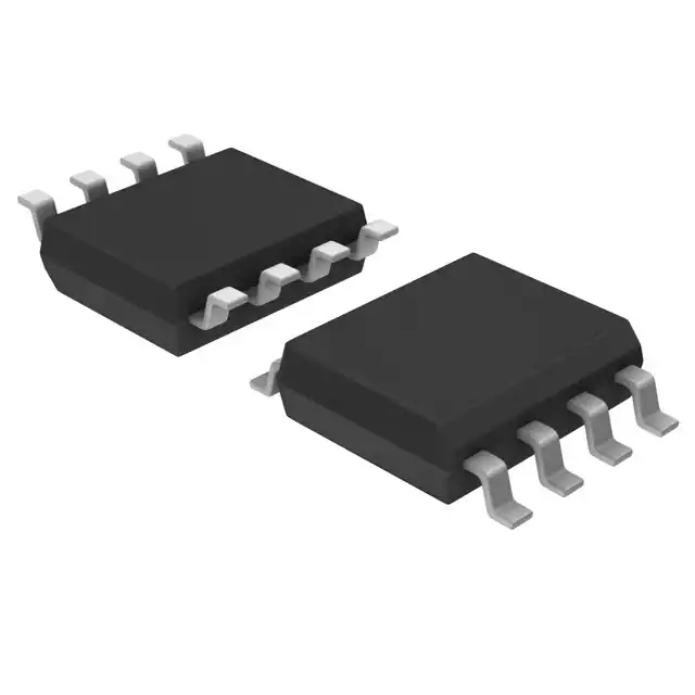
Analog Devices Inc./Maxim Integrated DS1075Z-60N
- Part No.:
- DS1075Z-60N
- Manufacturer:
- Analog Devices Inc./Maxim Integrated
- Category:
- Oscillators
- Package:
- 8-SOIC (0.154", 3.90mm Width)
- Datasheet:
-
 DS1075Z-60N.pdf
- Description:
- ECONOSCILL/DIV 60MHZ IND 8-SOIC
- Quantity:
- Payment:

- Shipping:

Inventory:420
Please send an inquiry. Send us your inquiry, and we will respond immediately.
Product details
Overview
DS1075Z-60N from Maxim Integrated is a programmable fixed-frequency oscillator IC generating dual outputs with user-configurable prescaler (÷1, ÷2, ÷4) and 9-bit divider (÷2 to ÷513), delivering precise 60 MHz maximum output from internal oscillator or external clock/crystal reference, operating on single 5V supply with 0.5% initial tolerance and 1% variation over temperature and voltage, used in embedded timing control and clock distribution systems.
For engineers reviewing the DS1075Z-60N datasheet, DS1075Z-60N pinout, DS1075Z-60N application, or DS1075Z-60N equivalent, this page provides verified functional identity, confirmed package mapping (150-mil SOIC), validated pin roles including synchronous OE gating and PDN/SELX dual-mode control, and real-world selection guidance against comparable programmable oscillators.
Technical Context
The DS1075Z-60N implements a master oscillator followed by a user-programmable prescaler and a 9-bit nonvolatile divider, with register values stored in EEPROM for field reprogramming. Its architecture supports three reference sources-internal oscillator, external clock, or crystal-and enables glitch-free switching between them via SELX mode or power-down via PDN mode.
It features synchronous output enable (OE) that holds OUT low at next high-to-low transition without pulse truncation, and a reference output (OUT0) buffered from the reference select mux, unaffected by OE but disabled during power-down. The IN/OUT pin serves as serial programming interface during power-up with pull-up, then becomes the primary oscillator output.
Key Specifications
| Parameter | Value and Actual Design Meaning |
|---|---|
| Max Output Frequency | 60.000 MHz - factory-configured maximum output frequency for DS1075Z-60N variant |
| Output Tolerance | ±0.5% - initial accuracy at 25°C, enabling stable timing without calibration |
| Freq. Variation | ±1% - guaranteed stability across full 0°C to 70°C operating temperature and 4.75–5.25V supply range |
| Supply Voltage | 4.75–5.25 V - single 5V rail operation compatible with standard TTL/CMOS logic domains |
| Power-Down Current | 0.8 µA - ultra-low quiescent current in PDN mode, critical for battery-backed or low-power standby systems |
| Programmable Divider Range | ÷2 to ÷513 - 9-bit N register allows fine-grained frequency synthesis down to 29.3 kHz minimum output |
| Prescaler Options | ÷1, ÷2, ÷4 - selectable M prescaler bypasses or scales master clock before N-divider stage |
Pinout & Package
DS1075Z-60N is housed in an industry-standard 8-pin 150-mil SOIC package (JEDEC MS-012), with 1.27 mm pitch, surface-mount compatible footprint, and thermal characteristics suitable for industrial ambient conditions (0°C to 70°C).
| Pin/Terminal | Circuit Role | Design Meaning |
|---|---|---|
| 1: IN/OUT | Serial Programming Input / Oscillator Output | Configurable bidirectional pin: accepts 1-Wire™ programming data on power-up with pull-up; becomes primary output (OUT) in operation mode |
| 2: OUT0 | Reference Clock Output | Buffered output of selected reference (INTCLK or EXTCLK), independent of OE, disabled only in power-down |
| 3: VCC | Positive Supply | Single 5V supply input; powers all internal circuitry including oscillator, dividers, and output buffers |
| 4: GND | Ground Reference | Common return path for supply and signal integrity; must be low-impedance for jitter-sensitive clock applications |
| 5: OSCIN | External Clock Input | Accepts up to 50 MHz external clock signal; used when crystal or internal oscillator is not selected |
| 6: PDN/SELX | Power-Down or Reference Select Control | User-configurable function: active-low PDN (power-down) or level-triggered SELX (internal/external reference switch) |
| 7: XTAL | Crystal Terminal | Connects to one side of external crystal (other side to OSCIN); left open if crystal not used |
| 8: OE | Synchronous Output Enable | Active-high control: enables free-running output; low forces OUT low at next high-to-low transition without pulse truncation |
Key Features
| Feature | Design Value |
|---|---|
| Dual fixed-frequency outputs | Provides both main clock (OUT) and reference buffer (OUT0) for system-level timing verification and clock tree redundancy |
| User-programmable nonvolatile registers | Enables field reconfiguration of prescaler/divider values without hardware change-ideal for design iteration and BOM consolidation |
| Synchronous output gating | OE control guarantees deterministic edge alignment and eliminates metastability-induced glitches during enable/disable transitions |
| Glitch-free reference switching | SELX mode uses enabling sequencer to switch between internal/external clocks with sub-cycle phase predictability |
| No external components required | Self-contained oscillator core eliminates need for load capacitors, resistors, or external PLL components-reduces board area and bill-of-materials |
Applications
| Microcontroller Clock Source | Industrial PLC Timing Module |
|---|---|
Use Scenario: Providing precise, stable clock to ARM Cortex-M or 8051-based microcontrollers in factory automation controllers. IC Role / Device Role / Timing Role: Primary system clock generator with programmable frequency scaling to match MCU core/peripheral requirements. Use Value: Eliminates need for multiple crystal options; single DS1075Z-60N supports multiple MCU variants via field programming of N-divider. | Use Scenario: Synchronizing I/O scan cycles and communication interfaces (RS-485, CAN) in programmable logic controllers. IC Role / Device Role / Timing Role: Central timing reference distributing synchronized clocks to CPU, ADC sampling, and serial interface modules. Use Value: ±1% frequency stability over temperature ensures deterministic scan timing across 0–70°C industrial environment. |
| Test Equipment Clock Generator | Legacy System Clock Upgrade |
Use Scenario: Generating variable test frequencies (e.g., 10 MHz, 25 MHz, 50 MHz) in automated test fixtures for digital IC validation. IC Role / Device Role / Timing Role: Programmable frequency source replacing fixed crystals or discrete oscillator circuits. Use Value: On-site reprogramming via evaluation board (DS1075K) enables rapid test setup changes without PCB respin. | Use Scenario: Replacing obsolete crystal oscillators in aging medical or telecom equipment where layout space is constrained. IC Role / Device Role / Timing Role: Drop-in-compatible timing upgrade using same 8-pin SOIC footprint and 5V supply. Use Value: Maintains original 60 MHz clock while adding power-down and output enable-extending product lifecycle without redesign. |
Equivalent & Alternatives
The following parts are listed as comparable options for similar programmable oscillator applications.
| Alternative Part | Technical Difference | Application Difference | Selection Advice |
|---|---|---|---|
| DS1077Z-60+ | Higher drive strength (10 mA vs. 4 mA), improved jitter (50 ps typ.), but no OUT0 reference output | Lacks dual-output capability; unsuitable where buffered reference monitoring is required | Choose DS1077Z-60+ only when higher output current or lower jitter is prioritized over reference output availability |
| Si5351A-B-GM | 3-output, I²C-programmable, wider frequency range (8 kHz–200 MHz), but requires external crystal and 3.3V supply | Not pin-compatible; needs level-shifting and additional passive components for 5V systems | Select Si5351A-B-GM only for multi-output, fine-resolution synthesis in new 3.3V designs-not for drop-in replacement |
Compared with DS1075Z-60N, DS1077Z-60+ offers superior electrical performance but sacrifices the diagnostic OUT0 output, while Si5351A-B-GM delivers greater flexibility at the cost of increased design complexity and incompatibility with existing 5V/8-pin SOIC layouts.
Availability
DS1075Z-60N is available at Aetrix Electronics and suitable for industrial control systems, test instrumentation, and legacy electronics upgrades requiring stable component supply, long-term obsolescence mitigation, and field-programmable timing flexibility.
Supply support for DS1075Z-60N includes scheduled delivery planning, volume procurement assistance, BOM continuity management, traceable sourcing, and lifecycle availability coordination for OEM customers, industrial embedded developers, connected-device designers, and electronics production programs.
Manufacturer
Maxim Integrated (now part of Analog Devices) is a semiconductor company specializing in precision analog, mixed-signal, and power management ICs for industrial, communications, and computing applications.
The DS1075Z-60N belongs to Maxim's EconOscillator/Divider family-designed to replace discrete crystal oscillators with integrated, field-programmable clock sources that reduce component count and simplify timing architecture in cost-sensitive embedded systems.
FAQ
What is the factory default configuration of the DS1075Z-60N?
The DS1075Z-60N ships with DIV = 000000000 (÷2), MUX = 00110100, EN0 = 1 (OUT0 disabled), PDN = 1 (PDN mode enabled), MSEL = 1 (prescaler bypassed), and E/I = 0 (internal oscillator selected). This yields a default output frequency of 30 MHz (60 MHz ÷ 2) with power-down functionality active and no reference output enabled.
Can the DS1075Z-60N operate with a 3.3V supply?
No, the DS1075Z-60N is specified only for 4.75–5.25V operation per its DC electrical characteristics. It lacks 3.3V logic compatibility, and applying 3.3V will result in undefined behavior or failure to oscillate. For 3.3V systems, consider alternatives like the Si5351A-B-GM, but note it requires layout and supply changes.
How does the synchronous OE function prevent output pulse truncation in the DS1075Z-60N?
The DS1075Z-60N uses an enabling sequencer that samples OE with the prescaler output (MCLK) and gates the divider output. When OE goes low, OUT is held low immediately if already low, or at the next high-to-low transition if high-ensuring no partial pulses. This deterministic behavior eliminates timing hazards in synchronous digital systems relying on clean clock edges.
Is the DS1075Z-60N pin-compatible with other DS1075 variants like DS1075Z-80N or DS1075Z-100N?
Yes, all DS1075Z-xN variants share identical 8-pin SOIC packaging, pinout, and register architecture. The suffix denotes maximum rated output frequency (60 MHz, 80 MHz, 100 MHz), but electrical pin functions, programming interface, and AC/DC specifications (except max fOUT and ICC) are fully interchangeable-enabling one PCB layout to support multiple speed grades.
What is the minimum output frequency achievable with the DS1075Z-60N?
The DS1075Z-60N supports a minimum output frequency of 29.3 kHz, achieved when using the internal 60 MHz oscillator with maximum prescaler (÷4) and maximum divider (÷513): 60 MHz ÷ 4 ÷ 513 ≈ 29.24 kHz. This meets the guaranteed specification under all operating conditions per the datasheet's AC Electrical Characteristics table.
DS1075Z-60N Specifications
- Product attributes
- Attribute value
- Manufacturer:
- Analog Devices Inc./Maxim Integrated
- Series:
- EconOscillator™
- Package/Case:
- 8-SOIC (0.154", 3.90mm Width)
- Packaging:
- Tube
- Product Status:
- Obsolete
- Base Resonator:
- -
- Type:
- -
- Frequency:
- 60 MHz
- Function:
- -
- Output:
- -
- Voltage - Supply:
- -
- Frequency Stability:
- -
- Absolute Pull Range (APR):
- -
- Operating Temperature:
- -
- Spread Spectrum Bandwidth:
- -
- Current - Supply (Max):
- -
- Ratings:
- -
- Mounting Type:
- Surface Mount
- Supplier Device Package:
- 8-SOIC
- Size / Dimension:
- -
- Height - Seated (Max):
- -
DS1075Z-60N FAQ
1.How can I place an order for DS1075Z-60N through Aetrix?
Please submit a Request for Quotation (RFQ) for DS1075Z-60N on Aetrix. Our sales agent will provide a competitive quotation and guide you through the order confirmation once you accept the terms.
2.Are the price and stock information for DS1075Z-60N reliable?
The price and inventory of DS1075Z-60N are updated periodically and may fluctuate due to market conditions. Stock and pricing data are typically refreshed every 24 hours. Quotation validity for DS1075Z-60N is usually 5 days.
3.What payment methods are accepted for DS1075Z-60N?
We accept Wire Transfer, PayPal, Credit Card, Western Union, MoneyGram, and Escrow for DS1075Z-60N transactions.
Note: Certain payment methods may incur a processing fee.
4.How is shipping managed for DS1075Z-60N?
DS1075Z-60N orders can be shipped via leading logistics carriers, including DHL, UPS, FedEx, TNT, or Registered Mail.
Once your DS1075Z-60N order is processed, you will receive an email with the shipment details and tracking number.
Note: Tracking information may take up to 24 hours to appear. Express delivery typically takes 3–5 business days.
5.How can I obtain technical support or documentation for DS1075Z-60N?
For technical support, including DS1075Z-60N datasheets, pinout diagrams, or application guidance, please contact our engineering support team. They can provide detailed documentation and assistance for your DS1075Z-60N requirements.
6.How does Aetrix verify that DS1075Z-60N is sourced from the original manufacturer or authorized distributors?
All DS1075Z-60N products on Aetrix are procured from qualified distributors and authorized channels. Our dedicated quality assurance team conducts strict verification, including traceability checks and, if necessary, third-party testing. This ensures that DS1075Z-60N meets industry standards.
7.What is the process for return or replacement of DS1075Z-60N?
All DS1075Z-60N units undergo pre-shipment inspection (PSI). If there is an issue with DS1075Z-60N, returns or replacements are accepted under the following conditions:
1.Quantity discrepancies, incorrect items, or visible external defects (such as breakage or corrosion), acknowledged by Aetrix.
2.The issue is reported within 90 days of delivery.
3.The DS1075Z-60N part is unused and in its original packaging.
Return procedure for DS1075Z-60N:
1.Submit a request within 90 days.
2.Obtain a Return Material Authorization (RMA) from Aetrix.
DS1075Z-60N Tags
-
ECS-2333-160-BN-TR
ECS Inc.
-
ECS-2333-240-BN-TR
ECS Inc.
-
KC2016Z25.0000C1KX00
KYOCERA AVX
-0.035-Thick.jpg)
-
ECS-2033-250-BN
ECS Inc.
-
O 25,0-JO32-B-1V3-1-T1-LF
Jauch Quartz
-
SIT1533AI-H4-DCC-32.768E
SiTime
-
ECS-2333-500-BN-TR
ECS Inc.
-
COM1305-50.000-EXT-T-TR
Raltron Electronics
-
SG-210STF 24.0000ML0
EPSON
-
ECS-3225MV-320-CN-TR
ECS Inc.
-
ECS-2033-240-BN
ECS Inc.
-
ECS-2333-120-BN-TR
ECS Inc.
Tech Hub

Comparator circuit design covering voltage thresholds, input limits, open-collector outputs, LM393 wiring, op-amp differences, hysteresis, timing, window detection and practical fault diagnosis.
Schmitt triggers use separate rising and falling thresholds to stabilize slow or noisy signals. This guide covers hysteresis, 74HC14 and 74HCT14 selection, comparator calculations, RC oscillators and p…

Counterfeit components can hide behind convincing markings and passing basic function tests. This engineering reference covers source traceability, external inspection, X-ray, XRF, electrical testing, …

A practical engineering and sourcing framework covering lifecycle verification, lifetime-buy calculations, replacement qualification, supplier checks and counterfeit-risk controls.

TTL and CMOS logic families differ in thresholds, loading, output drive, power and timing. This engineering guide compares 74HC and 74HCT, calculates noise margins and checks 3.3 V/5 V compatibility.

A practical engineering guide to 3.3V and 5V logic compatibility, input thresholds, resistor dividers, translator ICs, MOSFET level shifting, I2C pull-ups, timing limits and power-sequencing risks.

The 74HC595 uses push-pull logic outputs, while the TPIC6B595 uses 50 V open-drain DMOS sinks for higher-power loads. This guide compares timing, current limits, 3.3 V interfacing, load wiring, thermal…

The 74HC595 converts serial data into eight stable parallel outputs. This guide covers pin functions, shift and storage timing, OE and MR behavior, drive-current limits, cascading, voltage compatibilit…

A technical comparison of level-sensitive latches and edge-triggered flip-flops, covering timing windows, setup and hold limits, master–slave operation, time borrowing, race-through, HDL inference and…

A D latch stores one bit while Enable controls when data can pass. This reference covers gate-level operation, truth tables, transparency, setup and hold timing, LE versus OE, common ICs and practical …


