
 My Inquiry
 My Account


Infineon Technologies ESD1P0RFSH6327XTSA1
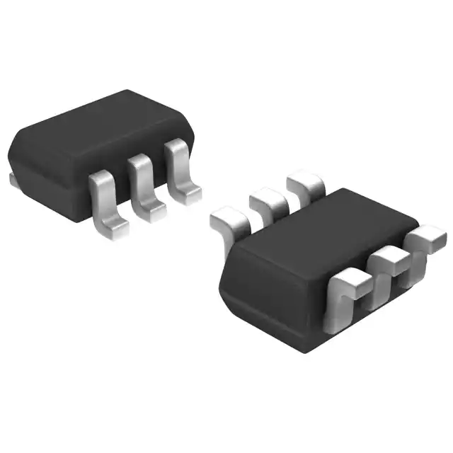
- Part No.:
- ESD1P0RFSH6327XTSA1
- Manufacturer:
- Infineon Technologies
- Category:
- TVS Diodes
- Package:
- 6-VSSOP, SC-88, SOT-363
- Datasheet:
-
 ESD1P0RFSH6327XTSA1.pdf
- Description:
- TVS DIODE 70VWM 15VC SOT363-6
- Quantity:
- Payment:

- Shipping:

Inventory:6,338
Please send an inquiry. Send us your inquiry, and we will respond immediately.
Product details
Overview
ESD1P0RFSH6327XTSA1 from Infineon Technologies is a one-line transient protection device designed for ESD, EFT, surge, and transient suppression in exposed electronic interfaces. The device belongs to the ESD1P0RFS protection family and is selected where working voltage, capacitance, clamping behavior, package footprint, and protected-line count must match the target circuit.
As an configuration of the ESD1P0RFS family, ESD1P0RFSH6327XTSA1 combines 1.0 pF-class RF protection family; working-voltage rating should be verified from the exact family datasheet working-voltage class, 1.0 pF RF-class capacitance, IEC61000-4-2 system-level ESD protection class, and a 6-VSSOP, SC-88, SOT-363 package. For engineers reviewing the ESD1P0RFSH6327XTSA1 datasheet, ESD1P0RFSH6327XTSA1 pinout, ESD1P0RFSH6327XTSA1 application, or ESD1P0RFSH6327XTSA1 equivalent, this device is commonly relevant to RF, audio, keypad, and compact mobile interface protection, connector-side protection, compact embedded boards, and system-level immunity design.
Technical Context
In a board-level protection design, ESD1P0RFSH6327XTSA1 should be placed close to the connector, exposed signal entry point, RF feed, control line, or supply node that may receive an ESD or surge event. Short routing is important because trace inductance can raise the residual voltage seen by the protected IC during fast IEC discharge pulses.
The transient structure, 1.0 pF-class RF protection family; working-voltage rating should be verified from the exact family datasheet working-voltage class, and 1.0 pF RF-class capacitance determine where the device can be used without excessive signal loading or unwanted clipping during normal operation.
Key Specifications
| Parameter | Value and Actual Design Meaning |
|---|---|
| Device Type | One-line transient protection device for line-level ESD and transient suppression. |
| Protection Function | One-line transient clamping behavior matched to the ESD1P0RFS family. |
| Working Voltage | 1.0 pF-class RF protection family; working-voltage rating should be verified from the exact family datasheet, defining the normal voltage range that should not trigger the protection structure. |
| Line Capacitance | 1.0 pF RF-class capacitance, important for RF, high-speed, audio, touchscreen, sensor, control, or power-line loading. |
| ESD Rating | IEC61000-4-2 system-level ESD protection class, supporting system-level ESD robustness when the PCB layout provides a short discharge path. |
| EFT Rating | EFT immunity should be verified against the exact device family rating, relevant to cable-connected and industrial environments where fast electrical transients may occur. |
| Surge / Peak Pulse Rating | surge or peak-pulse capability should be checked against the exact pulse waveform requirement, defining the short-duration pulse capability for non-repetitive transient events. |
| Reverse Leakage | low reverse leakage suitable for protected signal lines, supporting low-current or high-impedance protected signal paths. |
| Package | 6-VSSOP, SC-88, SOT-363 package, selected for placement close to connectors or protected IC pins. |
| Packing | Tape & Reel (TR) for SMT assembly and procurement handling. |
| Lifecycle / Design Status | verify latest Infineon lifecycle status before new production use. |
Pinout & Package
The ESD1P0RFSH6327XTSA1 pinout should be reviewed as a protection-device connection rather than a functional logic pinout. The relevant connections are the protected line terminal, reference or ground terminal where present, and any additional line terminals used by multi-line array versions.
For PCB design, ESD1P0RFSH6327XTSA1 should be placed ahead of the sensitive IC and close to the transient entry point. Land pattern, package orientation, solder mask, stencil opening, and inspection process should follow the manufacturer package drawing for the 6-VSSOP, SC-88, SOT-363 package.
| Pin / Function | PCB Design and Circuit Role |
|---|---|
| Protected Line Pin(s) | Connect to the exposed signal, data, RF, supply, or interface line protected by ESD1P0RFSH6327XTSA1. |
| Ground / Reference Pin | Connect directly to the local ground or reference return where the package configuration provides a dedicated return pin. |
| Bi-Directional Connection | For bi-directional options, the diode structure clamps positive and negative ESD stress around the protected line. |
| Uni-Directional Connection | For uni-directional options, orientation and return path must match the datasheet schematic and system polarity. |
| Package Footprint | 6-VSSOP, SC-88, SOT-363 footprint should be verified against the Infineon package drawing before PCB release. |
| Connector-Side Placement | Place the device close to the connector or transient entry point with short traces and low loop inductance. |
Key Features
- One-line transient protection for ESD and transient protection use.
- Working-voltage class: 1.0 pF-class RF protection family; working-voltage rating should be verified from the exact family datasheet.
- Line-capacitance class: 1.0 pF RF-class capacitance.
- ESD robustness: IEC61000-4-2 system-level ESD protection class.
- EFT capability: EFT immunity should be verified against the exact device family rating.
- Surge or peak-pulse capability: surge or peak-pulse capability should be checked against the exact pulse waveform requirement.
- 6-VSSOP, SC-88, SOT-363 package supports close placement at exposed interfaces.
- Tape & Reel (TR) supports SMT manufacturing flow.
- RoHS, lead-free, halogen-free, MSL, and lifecycle status should be verified from the exact documentation.
Applications
| RF Antenna Protection | Mobile Device Interfaces |
|---|---|
Use Scenario: LTE, WLAN, Bluetooth, GNSS, and compact radio antenna paths exposed to ESD during handling or connector use. IC Role: ESD1P0RFSH6327XTSA1 clamps discharge events while adding low capacitance to the RF path. Use Value: Helps protect RF front-end circuits without excessive detuning or insertion impact. | Use Scenario: Smartphones, tablets, wearables, camera modules, and wireless accessories with dense PCB layouts. IC Role: The protection diode is placed close to the exposed node or connector. Use Value: Supports compact protection placement in space-limited portable products. |
| High-Speed Low-Capacitance Lines | Industrial Wireless Modules |
Use Scenario: Signal paths where capacitance must remain lower than general-purpose TVS devices. IC Role: ESD1P0RFSH6327XTSA1 provides transient suppression with a capacitance class matched to high-speed or RF routing. Use Value: Maintains signal quality while improving board-level ESD robustness. | Use Scenario: IoT radio modules, sensor gateways, and connected embedded products using external or board antennas. IC Role: The device provides local ESD protection at the antenna or exposed RF input. Use Value: Improves field reliability for wireless embedded hardware. |
Equivalent & Alternatives
When evaluating ESD1P0RFSH6327XTSA1 equivalent devices, engineers should compare working voltage, direction type, capacitance, ESD rating, EFT and surge capability, clamping voltage, dynamic resistance, package footprint, packing, and lifecycle status.
| Alternative Part | Technical Difference | Application Difference | Selection Advice |
|---|---|---|---|
| ESD1P0RFS | Related Infineon protection-device family or package option with different voltage, capacitance, package, or lifecycle details. | Used when the target circuit needs similar ESD protection but can accept the electrical and footprint differences. | Verify VRWM, capacitance, clamping voltage, surge rating, polarity, package land pattern, and approved-source status before substitution. |
| ESD103-B1-02ELS | Related Infineon protection-device family or package option with different voltage, capacitance, package, or lifecycle details. | Used when the target circuit needs similar ESD protection but can accept the electrical and footprint differences. | Verify VRWM, capacitance, clamping voltage, surge rating, polarity, package land pattern, and approved-source status before substitution. |
| ESD105-B1-02EL | Related Infineon protection-device family or package option with different voltage, capacitance, package, or lifecycle details. | Used when the target circuit needs similar ESD protection but can accept the electrical and footprint differences. | Verify VRWM, capacitance, clamping voltage, surge rating, polarity, package land pattern, and approved-source status before substitution. |
| ESD112-B1-02EL | Related Infineon protection-device family or package option with different voltage, capacitance, package, or lifecycle details. | Used when the target circuit needs similar ESD protection but can accept the electrical and footprint differences. | Verify VRWM, capacitance, clamping voltage, surge rating, polarity, package land pattern, and approved-source status before substitution. |
Compared with a generic TVS diode, ESD1P0RFSH6327XTSA1 should be selected by protected-line voltage, capacitance budget, residual clamping voltage, package land pattern, and system-level validation result rather than by package size alone.
Quality
ESD1P0RFSH6327XTSA1 should be sourced as original Infineon Technologies components through traceable and controlled supply channels. Quality verification may include reel-label inspection, package inspection, top-mark review, date-code review, solderability evaluation, and incoming sampling based on production risk.
Because small ESD and TVS devices are often placed at external interfaces, correct storage, ESD-safe handling, MSL control, land-pattern accuracy, and traceability are important for stable assembly yield and reliable field protection.
Availability
ESD1P0RFSH6327XTSA1 available at Aetrix Electronics and suitable for RF, audio, keypad, and compact mobile interface protection, connector-side transient suppression, compact embedded boards, and line-level ESD protection designs requiring traceable component supply.
Supply support may include scheduled delivery planning, tape-and-reel sourcing, BOM continuity assistance, replacement review, and long-term availability support for OEM manufacturers, EMS providers, repair facilities, and embedded hardware developers.
For production deployment, confirming package code, working voltage, capacitance, clamping voltage, ESD rating, lifecycle status, and approved substitute options helps reduce procurement risk and improve manufacturing stability.
Manufacturer
Infineon Technologies supplies semiconductor products including discrete protection devices, power semiconductors, microcontrollers, sensors, security ICs, and system-level components for industrial, automotive, communication, computing, and consumer electronics applications.
The ESD1P0RFS family is part of the manufacturer protection-device portfolio for line-level ESD and transient suppression. ESD1P0RFSH6327XTSA1 is positioned for applications where voltage, capacitance, clamping behavior, and package footprint must match the target PCB.
FAQ
What is ESD1P0RFSH6327XTSA1 used for?
ESD1P0RFSH6327XTSA1 is used for ESD, EFT, surge, and transient protection of exposed signal, RF, interface, or supply lines where compact PCB placement and controlled clamping behavior are required.
Where can I find the ESD1P0RFSH6327XTSA1 datasheet download?
The ESD1P0RFSH6327XTSA1 datasheet or datasheet is available through manufacturer resources for the ESD1P0RFS device family and includes electrical ratings, package data, and ordering information.
What should be considered in ESD1P0RFSH6327XTSA1 pinout design?
Pinout design should focus on device polarity, package orientation, protected-line routing, reference return inductance, and placement close to the connector or transient entry point.
Is ESD1P0RFSH6327XTSA1 suitable for high-speed or RF lines?
It may be suitable when the capacitance and clamping behavior match the signal bandwidth, insertion-loss, interface-voltage, and system-level protection requirements.
What matters most when selecting a ESD1P0RFSH6327XTSA1 equivalent?
Equivalent selection should compare working voltage, capacitance, ESD rating, clamping voltage, dynamic resistance, package footprint, lifecycle status, and validation results.
ESD1P0RFSH6327XTSA1 Specifications
- Product attributes
- Attribute value
- Manufacturer:
- Infineon Technologies
- Package/Case:
- 6-VSSOP, SC-88, SOT-363
- Series:
- -
- Packaging:
- Tape & Reel (TR)
- Product Status:
- Obsolete
- Type:
- Steering (Rail to Rail)
- Unidirectional Channels:
- 2
- Bidirectional Channels:
- -
- Voltage - Reverse Standoff (Typ):
- 70V (Max)
- Voltage - Breakdown (Min):
- -
- Voltage - Clamping (Max) @ Ipp:
- 15V
- Current - Peak Pulse (10/1000µs):
- 10A (8/20µs)
- Power - Peak Pulse:
- -
- Power Line Protection:
- No
- Applications:
- Ethernet, HDMI, RF Antenna
- Capacitance @ Frequency:
- 1pF @ 1MHz
- Operating Temperature:
- -55°C ~ 150°C (TJ)
- Grade:
- -
- Qualification:
- -
- Mounting Type:
- Surface Mount
- Supplier Device Package:
- PG-SOT363-PO
ESD1P0RFSH6327XTSA1 FAQ
1.How can I place an order for ESD1P0RFSH6327XTSA1 through Aetrix?
Please submit a Request for Quotation (RFQ) for ESD1P0RFSH6327XTSA1 on Aetrix. Our sales agent will provide a competitive quotation and guide you through the order confirmation once you accept the terms.
2.Are the price and stock information for ESD1P0RFSH6327XTSA1 reliable?
The price and inventory of ESD1P0RFSH6327XTSA1 are updated periodically and may fluctuate due to market conditions. Stock and pricing data are typically refreshed every 24 hours. Quotation validity for ESD1P0RFSH6327XTSA1 is usually 5 days.
3.What payment methods are accepted for ESD1P0RFSH6327XTSA1?
We accept Wire Transfer, PayPal, Credit Card, Western Union, MoneyGram, and Escrow for ESD1P0RFSH6327XTSA1 transactions.
Note: Certain payment methods may incur a processing fee.
4.How is shipping managed for ESD1P0RFSH6327XTSA1?
ESD1P0RFSH6327XTSA1 orders can be shipped via leading logistics carriers, including DHL, UPS, FedEx, TNT, or Registered Mail.
Once your ESD1P0RFSH6327XTSA1 order is processed, you will receive an email with the shipment details and tracking number.
Note: Tracking information may take up to 24 hours to appear. Express delivery typically takes 3–5 business days.
5.How can I obtain technical support or documentation for ESD1P0RFSH6327XTSA1?
For technical support, including ESD1P0RFSH6327XTSA1 datasheets, pinout diagrams, or application guidance, please contact our engineering support team. They can provide detailed documentation and assistance for your ESD1P0RFSH6327XTSA1 requirements.
6.How does Aetrix verify that ESD1P0RFSH6327XTSA1 is sourced from the original manufacturer or authorized distributors?
All ESD1P0RFSH6327XTSA1 products on Aetrix are procured from qualified distributors and authorized channels. Our dedicated quality assurance team conducts strict verification, including traceability checks and, if necessary, third-party testing. This ensures that ESD1P0RFSH6327XTSA1 meets industry standards.
7.What is the process for return or replacement of ESD1P0RFSH6327XTSA1?
All ESD1P0RFSH6327XTSA1 units undergo pre-shipment inspection (PSI). If there is an issue with ESD1P0RFSH6327XTSA1, returns or replacements are accepted under the following conditions:
1.Quantity discrepancies, incorrect items, or visible external defects (such as breakage or corrosion), acknowledged by Aetrix.
2.The issue is reported within 90 days of delivery.
3.The ESD1P0RFSH6327XTSA1 part is unused and in its original packaging.
Return procedure for ESD1P0RFSH6327XTSA1:
1.Submit a request within 90 days.
2.Obtain a Return Material Authorization (RMA) from Aetrix.
ESD1P0RFSH6327XTSA1 Tags

-
ESD9B5.0ST5G
onsemi

-
DESD3V3E1BL-7B
Diodes Incorporated

-
ESD5Z3.3T1G
onsemi
-
D5V0H1B2LP-7B
Diodes Incorporated
-
D5V0P1B2LP-7B
Diodes Incorporated

-
DESD5V0U1BA-7
Diodes Incorporated
-
ESD5Z5.0T1G
onsemi

-
DESD5V0U1BB-7
Diodes Incorporated
-
D12V0L1B2LP-7B
Diodes Incorporated

-
PESD2V0Y1BSFYL
Nexperia USA Inc.

-
DF2S5M4CT,L3F
Toshiba Semiconductor and Storage
-
D5V0L1B2WS-7
Diodes Incorporated
Tech Hub

Engineering guide to output capacitor selection for ASIC Vcore rails, covering bulk capacitors, polymer capacitors, MLCC decoupling, DC bias, ESR, ESL, placement, transient response and substitution ri…

Engineering guide to high-current ASIC Vcore rails, covering 12-phase buck architecture, PMBus control, dynamic load testing, output capacitor networks, smart power stage selection, thermal design and …

Voltage regulator guide covering linear, LDO, 7805, Zener, adjustable, buck, VRM and alternator regulators, with design checks, testing methods, troubleshooting and datasheet-based selection.

Amplifier guide covering voltage, current and power amplification, gain, feedback, amplifier classes, audio and RF applications, op-amp circuits, transimpedance amplifiers, datasheet selection and trou…

Machine vision system guide covering components, inspection workflow, camera and lens selection, FOV, pixel resolution, motion blur, strobe lighting, bandwidth, 2D/3D vision, integration, troubleshooti…

Electronic devices and circuits guide covering passive components, semiconductors, analog and digital circuits, circuit theory, practical calculations, troubleshooting, datasheet selection, and learnin…

Oil pressure sensor diagnosis covering symptoms, location, testing, replacement, socket access, common failure cases, and the electronic signal path between the pressure sensor, wiring, ECU and gauge s…

MLCC ESR, impedance and self-resonant frequency in decoupling networks. Covers PDN behavior, frequency response, measurement methods, failure cases and practical capacitor selection for power integrity…

An actuator converts a control signal and energy source into mechanical motion. This guide explains actuator types, working principles, electric and linear actuators, automotive use cases, troubleshoot…

A potentiometer is a three-terminal adjustable resistor used for voltage division, analog control, calibration and signal adjustment. This guide explains wiring, symbols, types, 10k values, digital pot…


