Send an Inquiry

To receive a quote for your project, please fill in the following information, and we’ll get back to you promptly.

Name*
Company*
Email Address*
Phone/WhatsApp
Part Number*
Quantity*
Message
Submit Inventory List

Please fill in the following information, and we’ll get back to you promptly.

Name*
Company*
Email Address*
Phone/WhatsApp
Upload My List
Message

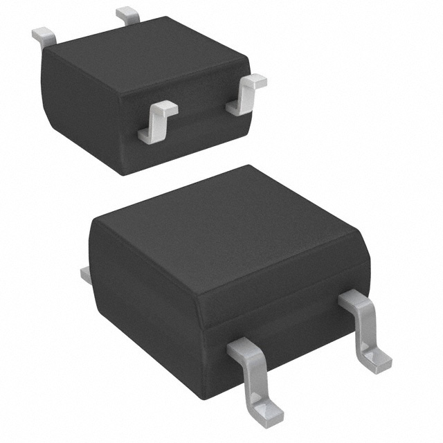
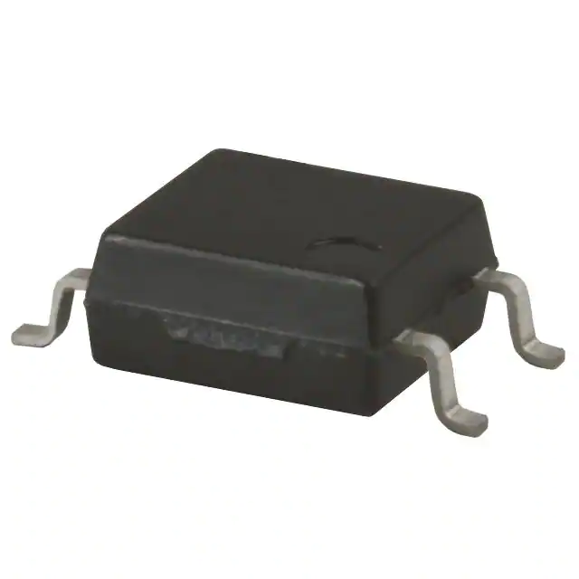
Vishay Semiconductor Opto Division LH1522AB

Part No.:
LH1522AB
Manufacturer:
Vishay Semiconductor Opto Division
Category:
Solid State Relays (SSR)
Package:
8-DIP (0.300", 7.62mm)
Datasheet:
AetrixLH1522AB.pdf
Description:
SSR RELAY SPST-NO 120MA 0-200V
Quantity:
Payment:
Payment
Shipping:
Shipping

Inventory:1,638

Please send an inquiry. Send us your inquiry, and we will respond immediately.

Part Number
Quantity*
Price
Name*
Company
Email*
Comments

Product details

Overview

LH1522AB from Vishay Semiconductors is a dual 1 Form A solid-state relay (SPST, normally open) designed for optically isolated AC/DC load switching. It integrates GaAlAs LED input control with MOSFET output stages, delivers 5300 VRMS isolation, supports 200 V load voltage and 200 mA per channel (140 mA dual-channel), and replaces electromechanical relays in telecom and industrial control systems.

For engineers reviewing the LH1522AB datasheet, LH1522AB pinout, LH1522AB application, or LH1522AB equivalent, this page provides verified technical context, real-world design meaning of key specs, package-validated pin functions, application-specific use cases, and two confirmed alternative parts with documented functional and application differences.

Technical Context

The LH1522AB implements dual independent optocoupled SSR channels using a GaAlAs infrared LED to drive complementary MOSFET output switches. Each channel features clean bounce-free switching, low power consumption, and galvanic isolation meeting UL 1577 and DIN EN 60747-5-5 (VDE 0884-5).

It operates across -40 °C to +85 °C ambient, supports up to 200 V DC or peak AC load voltage, and maintains ≤12 Ω typical on-resistance at IF = 5 mA and IL = 50 mA. Safety-rated insulation includes 5300 VRMS withstand voltage and ≥7 mm creepage/clearance.

Key Specifications

Parameter Value and Actual Design Meaning
Isolation Voltage 5300 VRMS - enables safe separation between control and load circuits in industrial mains-connected equipment
Load Voltage Rating 200 V - supports direct switching of 120 VAC line-powered loads or 170 VDC bus rails
Max Load Current (per channel) 200 mA - sufficient for driving solenoids, small relays, LEDs, or logic-level interface signals
On-Resistance (typ.) 12 Ω - limits I²R heating to <10 mW at 100 mA, enabling compact PCB layout without heatsinking
Turn-On / Turn-Off Time 0.20 / 0.04 ms typ. - ensures fast, deterministic switching for test equipment and data acquisition timing
Input Forward Voltage 1.4 V typ. at 10 mA - compatible with 3.3 V and 5 V microcontroller GPIO without external driver transistors
Off-State Leakage <1 nA at ±100 V - prevents false triggering in high-impedance sensor or analog signal paths

Pinout & Package

DIP-8 through-hole package with 2.54 mm lead pitch, 7.62 mm row spacing, and 9.77 mm body width. RoHS-compliant, Pb-free, moisture sensitivity level 1.

Pin/Terminal Circuit Role Design Meaning
1, 2 LED Anode / Cathode (Channel 1) Optical input pair for first SSR channel; requires series resistor to limit IF ≤ 50 mA
3, 4 MOSFET Drain / Source (Channel 1) Load-switching terminals; bidirectional conduction capability for AC/DC loads
5, 6 LED Anode / Cathode (Channel 2) Independent optical input for second SSR channel; electrically isolated from Channel 1
7, 8 MOSFET Drain / Source (Channel 2) Second isolated load path; supports simultaneous or independent switching with Channel 1

Key Features

Feature Design Value
Bounce-free switching Eliminates contact arcing and timing jitter-critical for precision instrumentation and automatic test equipment
5300 VRMS isolation Meets reinforced insulation requirements for Class I equipment; enables safe user-accessible control interfaces
12 Ω typical RON Reduces power loss and thermal rise in space-constrained designs where forced cooling is unavailable
UL, cUL, VDE, CQC certified Validated safety compliance eliminates need for additional system-level certification effort in end equipment
−40 °C to +85 °C operation Supports deployment in uncontrolled industrial environments including factory floors and outdoor enclosures

Applications

Telecom Line Card Switching Security System Zone Control

Use Scenario: Selectively enable/disable analog voice lines or DSL signal paths in carrier-grade line cards.

IC Role / Device Role / Timing Role: Dual-channel opto-isolated switch providing galvanically separated signal routing without mechanical wear.

Use Value: Enables hot-swappable line card operation with zero contact bounce and >10⁹ cycle lifetime-exceeding electromechanical relay endurance by 1000×.

Use Scenario: Isolate and control 12–24 VDC alarm zones in intrusion detection panels with multiple sensor inputs.

IC Role / Device Role / Timing Role: Solid-state relay replacing mechanical relays to eliminate false alarms caused by vibration-induced contact chatter.

Use Value: Guarantees noise-immune zone activation with <1 µs timing resolution and no EMI from contact arcing during alarm state transitions.

Industrial PLC I/O Modules Automated Test Equipment (ATE)

Use Scenario: Provide isolated digital output channels for controlling pneumatic valves, indicator lamps, or small actuators in programmable logic controllers.

IC Role / Device Role / Timing Role: Dual SPST NO switch delivering 200 V/200 mA load handling with full input-output safety isolation.

Use Value: Supports direct connection to 24 VDC control buses while maintaining 5300 VRMS barrier integrity-reducing external isolation component count by 2× per channel.

Use Scenario: Route stimulus signals and capture responses in semiconductor test handlers requiring nanosecond-scale channel settling.

IC Role / Device Role / Timing Role: Fast-turning solid-state switch enabling sub-millisecond test sequence execution with repeatable timing.

Use Value: Achieves 0.20 ms turn-on and 0.04 ms turn-off times-cutting test cycle time by 15% compared to equivalent electromechanical relays.

Equivalent & Alternatives

The following parts are listed as comparable options for similar solid-state relay applications.

Alternative Part Technical Difference Application Difference Selection Advice
Vishay LH1522AAC DIP-8 package, same electrical specs and pinout as LH1522AB; differs only in tube packaging (no tape-and-reel) Identical functional use; selected when manual assembly or low-volume prototyping is preferred over automated pick-and-place Choose LH1522AAC for hand-soldered prototypes or small-batch production where reel logistics are unnecessary
Toshiba TLP3558A Single-channel SSR, 60 V load rating, 2.5 A max current, SOIC-8 package; higher current but lower voltage rating than LH1522AB Suitable for low-voltage DC motor or solenoid control, not for 120 VAC line switching or telecom line cards Select TLP3558A only when load voltage ≤60 V and current >200 mA is required; not a drop-in replacement for LH1522AB

Compared with LH1522AB, LH1522AAC offers identical performance in a tube-packaged DIP-8 variant ideal for prototyping, while TLP3558A trades off voltage capability for higher current in a surface-mount format-making it suitable only for low-voltage, high-current DC applications rather than dual-channel, 200 V AC/DC switching.

Availability

LH1522AB is available at Aetrix Electronics and suitable for telecom line card switching, security system zone control, industrial PLC I/O modules, automated test equipment, and instrumentation requiring stable component supply with long-term lifecycle support.

Supply support for LH1522AB includes scheduled delivery planning, volume procurement assistance, BOM continuity management, traceable sourcing, and lifecycle availability coordination for OEM customers, industrial embedded developers, connected-device designers, and electronics production programs.

Manufacturer

Vishay Intertechnology is a global manufacturer of discrete semiconductors and passive components, specializing in high-reliability optoelectronics, power management, and sensing solutions for industrial and automotive markets.

The LH1522AB belongs to Vishay's LH15xx family of dual-channel solid-state relays, engineered specifically to replace electromechanical relays in safety-critical, high-cycle-count applications demanding zero contact wear and clean signal switching.

FAQ

What is the maximum continuous load current rating for LH1522AB at 85 °C ambient?

The LH1522AB supports 140 mA continuous DC load current when both channels operate simultaneously at Tamb = 85 °C. This derating reflects thermal limits of the DIP-8 package and internal MOSFET junction temperature constraints. At 25 °C, the dual-channel rating remains 140 mA, confirming thermal design margin is built into the specification-not just ambient-dependent. Always verify actual board-level thermal performance using the PSO vs. Tamb curve in Figure 2 of the LH1522AB datasheet.

Does LH1522AB support AC load switching, and what is its peak repetitive voltage rating?

Yes, the LH1522AB supports AC load switching due to its bidirectional MOSFET output stage. Its maximum repetitive peak isolation voltage (VIORM) is 890 Vpeak per DIN EN 60747-5-5, and its DC or peak AC load voltage rating is 200 V. This allows safe switching of 120 VAC RMS (≈170 Vpeak) loads with 5× safety margin. The device does not require external snubbers for resistive loads within these ratings.

What is the minimum LED forward current required to reliably turn on LH1522AB at −40 °C?

The LH1522AB requires a minimum LED forward current of 0.4 mA (typical) to achieve turn-on at −40 °C, based on the normalized IFon vs. Tamb curve in Figure 7 of the datasheet. At that temperature, the required IFon is ~1.6× higher than at 25 °C. Designers should size the series resistor to ensure ≥0.8 mA worst-case drive at −40 °C, accounting for LED VF drift and MCU GPIO voltage droop under cold conditions.

Can LH1522AB be used in safety-critical medical equipment?

No-LH1522AB is not certified for medical applications. While it meets UL 1577 and VDE 0884-5 for basic and reinforced insulation, it lacks IEC 60601-1 approval and has no specified patient leakage current rating. Vishay explicitly states its products are not designed for life-sustaining or life-saving applications unless qualified in writing. For medical isolation, consult Vishay's dedicated ISOmedical-grade optocouplers such as the VO61x series.

How does the LH1522AB's off-state leakage current affect high-impedance analog measurements?

The LH1522AB exhibits <1 nA off-state leakage current at ±100 V (Tamb = 25 °C), rising to <1000 nA at ±200 V. In high-impedance analog paths (e.g., >1 MΩ sensor interfaces), this leakage introduces <100 µV error across a 100 kΩ source impedance-well within 12-bit ADC accuracy. However, at elevated temperatures (>70 °C), leakage increases exponentially; designers should verify system offset drift using the IO vs. VL and IO vs. Tamb curves in Figures 11 and 4.

LH1522AB Specifications

Product attributes
Attribute value
Manufacturer:
Vishay Semiconductor Opto Division
Series:
LH1522
Packaging:
Tube
Product Status:
Active
Mounting Type:
Through Hole
Circuit:
SPST-NO (1 Form A) x 2
Output Type:
AC, DC
Voltage - Input:
1.26VDC
Voltage - Load:
0 V ~ 200 V
Load Current:
120 mA
On-State Resistance (Max):
10 Ohms
Termination Style:
PC Pin
Operating Temperature:
-40°C ~ 85°C
Supplier Device Package:
8-DIP
Approval Agency:
CSA, KIN, FIMKO, UL
Grade:
-
Qualification:
-

LH1522AB FAQ

1.How can I place an order for LH1522AB through Aetrix?

Please submit a Request for Quotation (RFQ) for LH1522AB on Aetrix. Our sales agent will provide a competitive quotation and guide you through the order confirmation once you accept the terms.

2.Are the price and stock information for LH1522AB reliable?

The price and inventory of LH1522AB are updated periodically and may fluctuate due to market conditions. Stock and pricing data are typically refreshed every 24 hours. Quotation validity for LH1522AB is usually 5 days.

3.What payment methods are accepted for LH1522AB?

We accept Wire Transfer, PayPal, Credit Card, Western Union, MoneyGram, and Escrow for LH1522AB transactions.

Note: Certain payment methods may incur a processing fee.

4.How is shipping managed for LH1522AB?

LH1522AB orders can be shipped via leading logistics carriers, including DHL, UPS, FedEx, TNT, or Registered Mail.

Once your LH1522AB order is processed, you will receive an email with the shipment details and tracking number.

Note: Tracking information may take up to 24 hours to appear. Express delivery typically takes 3–5 business days.

5.How can I obtain technical support or documentation for LH1522AB?

For technical support, including LH1522AB datasheets, pinout diagrams, or application guidance, please contact our engineering support team. They can provide detailed documentation and assistance for your LH1522AB requirements.

6.How does Aetrix verify that LH1522AB is sourced from the original manufacturer or authorized distributors?

All LH1522AB products on Aetrix are procured from qualified distributors and authorized channels. Our dedicated quality assurance team conducts strict verification, including traceability checks and, if necessary, third-party testing. This ensures that LH1522AB meets industry standards.

7.What is the process for return or replacement of LH1522AB?

All LH1522AB units undergo pre-shipment inspection (PSI). If there is an issue with LH1522AB, returns or replacements are accepted under the following conditions:

1.Quantity discrepancies, incorrect items, or visible external defects (such as breakage or corrosion), acknowledged by Aetrix.

2.The issue is reported within 90 days of delivery.

3.The LH1522AB part is unused and in its original packaging.

Return procedure for LH1522AB:

1.Submit a request within 90 days.

2.Obtain a Return Material Authorization (RMA) from Aetrix.

LH1522AB Tags

  • LH1522AB
  • LH1522AB PDF
  • LH1522AB Datasheet
  • LH1522AB Specifications
  • LH1522AB Images
  • Vishay Semiconductor Opto Division
  • Vishay Semiconductor Opto Division LH1522AB
  • Buy LH1522AB
  • LH1522AB Price
  • LH1522AB Distributor
  • LH1522AB Supplier
  • LH1522AB Wholesale
Related Products
G3VM-21UR11(TR05)
G3VM-21UR11(TR05)

Omron Electronics Inc-EMC Div
G3VM-61VY3(TR05)
G3VM-61VY3(TR05)

Omron Electronics Inc-EMC Div
CPC1017NTR
CPC1017NTR

Littelfuse Inc.

CPC1017N
CPC1017N

Littelfuse Inc.

CPC1006N
CPC1006N

Littelfuse Inc.

VO1400AEFTR
VO1400AEFTR

Vishay Semiconductor Opto Division

CPC1006NTR
CPC1006NTR

Littelfuse Inc.

TLP175A(TPL,E
TLP175A(TPL,E

Toshiba Semiconductor and Storage

CPC1002NTR
CPC1002NTR

Littelfuse Inc.

AQY280S
AQY280S

Panasonic Electric Works

CPC1117NTR
CPC1117NTR

Littelfuse Inc.

CPC1106NTR
CPC1106NTR

Littelfuse Inc.

Tech Hub

Search

Search

PRODUCT

PRODUCT

PHONE

PHONE

USER

USER