
 My Inquiry
 My Account


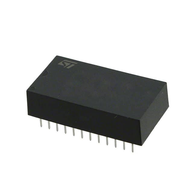
STMicroelectronics M48Z02-70PC1
- Part No.:
- M48Z02-70PC1
- Manufacturer:
- STMicroelectronics
- Category:
- Memory
- Package:
- 24-DIP Module (0.600", 15.24mm)
- Datasheet:
-
 M48Z02-70PC1.pdf
- Description:
- IC NVSRAM 16KBIT PAR 24PCDIP
- Quantity:
- Payment:

- Shipping:

Inventory:2,981
Please send an inquiry. Send us your inquiry, and we will respond immediately.
Product details
Overview
M48Z02-70PC1 from STMicroelectronics is a 16 kbit (2 Kb × 8) non-volatile ZEROPOWER® SRAM with integrated lithium battery, CAPHAT™ DIP package, 70 ns access time, and automatic power-fail write protection. It functions as a drop-in replacement for JEDEC-standard 2 K × 8 SRAMs (e.g., DS1220) in real-time clock backup, configuration storage, and firmware parameter retention applications.
For engineers reviewing the M48Z02-70PC1 datasheet, M48Z02-70PC1 pinout, M48Z02-70PC1 application, or M48Z02-70PC1 equivalent, this page delivers verified timing specs, battery-backed retention behavior, VPFD voltage thresholds, pin-level control logic, and functional alternatives for legacy system upgrades requiring guaranteed 10-year data retention without external backup circuitry.
Technical Context
The M48Z02-70PC1 integrates a 2 K × 8 static RAM array, ultra-low-power voltage-sensing circuitry, and a sealed lithium button cell within a 24-pin PDIP CAPHAT™ package. Its power-fail detection triggers write protection when VCC falls between 4.5 V and 4.75 V (VPFD window), then seamlessly switches to battery backup at ≤3.0 V (VSO).
It supports standard TTL/CMOS-compatible control signals (E, G, W) with ripple-through read access, identical read/write cycle times (70 ns), and automatic high-impedance output disable during power transition. The BOK (Battery OK) flag enables runtime battery health verification via software-read complement check sequence.
Key Specifications
| Parameter | Value and Actual Design Meaning |
|---|---|
| Memory size | 16 kbit (2,048 × 8 bits); provides byte-wide non-volatile storage without external EEPROM or flash interface logic. |
| Access time | 70 ns (tAVQV); enables direct interfacing with 14 MHz microcontrollers without wait states. |
| VPFD range | 4.5 V to 4.75 V; defines precise voltage window where chip deselect and write protection activate before brownout corruption. |
| VSO threshold | 3.0 V; switchover point where internal lithium battery powers SRAM, sustaining data integrity during full VCC loss. |
| Data retention | ≥10 years at 0–70 °C; achieved via hermetically sealed CAPHAT™ package and low-self-discharge LiCFx battery. |
| Supply voltage | 4.75 V to 5.5 V; compatible with standard +5 V logic rails and tolerant of typical regulator ripple. |
| Standby current | 3 mA (ICC1/ICC2); ultra-low quiescent draw during E = VIH or E = VCC – 0.2 V, minimizing system power budget impact. |
Pinout & Package
24-pin plastic DIP (PDIP24.7) with integrated CAPHAT™ battery housing; 600 mil width, 0.3 inch lead pitch, RoHS-compliant lead-free second-level interconnect.
| Pin/Terminal | Circuit Role | Design Meaning |
|---|---|---|
| A0–A10 | Address inputs | 11-bit address bus selecting one of 2,048 memory locations; compatible with standard 2 K × 8 SRAM addressing. |
| DQ0–DQ7 | Data I/O | Bi-directional 8-bit data bus; three-state controlled by E and G; supports shared bus architectures. |
| E | Chip enable | Active-low signal enabling memory access; high state forces outputs to Hi-Z and disables internal array. |
| G | Output enable | Active-low signal gating output drivers; allows read data to appear only when both E and G are asserted. |
| W | Write enable | Active-low signal initiating write cycles; falling edge synchronizes data latch; must meet tDVWH/tWHDX timing. |
| VCC | Power supply | +5 V primary supply input; monitored continuously for VPFD/VSO transitions; powers SRAM and control logic. |
| VSS | Ground | Reference return path for all digital and analog circuitry; requires low-inductance connection to minimize noise coupling. |
Key Features
| Feature | Design Value |
|---|---|
| Integrated lithium battery | Sealed LiCFx cell inside CAPHAT™ package delivers ≥10-year data retention without external components or charging circuitry. |
| Automatic power-fail response | Hardware-level VPFD detection disables writes and isolates I/O within microseconds when VCC drops into 4.5–4.75 V window. |
| Unlimited write endurance | No wear-out mechanism - unlike flash or EEPROM - supports infinite WRITE cycles without degradation or erase overhead. |
| Battery OK (BOK) flag | Self-checking status bit readable at power-up; blocks first write if battery voltage insufficient, preventing silent data loss. |
| JEDEC pin/function compatibility | Direct replacement for DS1220 and other 2 K × 8 SRAMs; fits ROM/EPROM sockets without PCB redesign or adapter. |
Applications
| Real-Time Clock (RTC) Backup | Firmware Configuration Storage |
|---|---|
|
Use Scenario: Maintaining time/date registers and alarm settings across AC power loss in industrial controllers. IC Role / Device Role / Timing Role: Non-volatile SRAM holding RTC register map; powered by internal battery during main supply interruption. Use Value: Eliminates need for external battery holder, diode-OR circuit, or supercapacitor, reducing BOM count and board space by 3+ components. |
Use Scenario: Storing calibration coefficients, network MAC addresses, and user preferences in medical diagnostic equipment. IC Role / Device Role / Timing Role: Byte-addressable configuration memory accessed during boot and runtime; retains values across cold restarts. Use Value: Enables field-upgradable parameters without flash reprogramming delays or sector-erase constraints - zero latency writes. |
| Industrial PLC Parameter Retention | Legacy System ROM Replacement |
|
Use Scenario: Preserving ladder logic scan counters, I/O mapping tables, and fault history logs during factory line power dips. IC Role / Device Role / Timing Role: High-reliability data vault with hardware write-protection triggered by brownout, preventing corruption during voltage sag. Use Value: Guarantees deterministic data integrity under worst-case 300 µs VCC fall time (tF), meeting IEC 61000-4-11 immunity requirements. |
Use Scenario: Upgrading obsolete EPROM-based boot loaders in telecom base station management cards without changing socket footprint. IC Role / Device Role / Timing Role: Pin- and function-compatible drop-in replacement for 27C16/2716 EPROMs, supporting in-system writes. Use Value: Removes UV eraser dependency and programming hardware; enables field updates via existing microcontroller firmware. |
Equivalent & Alternatives
The following parts are listed as comparable options for similar non-volatile SRAM applications.
| Alternative Part | Technical Difference | Application Difference | Selection Advice |
|---|---|---|---|
| DS1225Y-150+ | 5 V, 16 kbit, 150 ns access, external battery; no integrated BOK flag or VPFD hysteresis. | Lacks automatic power-fail write protect; requires external voltage monitor and discrete battery management. | Select when board layout already accommodates external battery and system firmware handles brownout sequencing. |
| M48Z12-70PC1 | Same package and timing, but VPFD = 4.2–4.5 V and VCC range = 4.5–5.5 V; lower VPFD threshold. | Better suited for systems with tighter 5 V rail tolerance or wider input voltage variation (e.g., automotive accessory rails). | Choose for designs operating near 4.5 V minimum VCC where M48Z02's 4.5 V VPFD min may cause premature write protect activation. |
Compared with DS1225Y-150+, M48Z02-70PC1 reduces system-level validation effort by integrating VPFD logic and battery health monitoring; compared with M48Z12-70PC1, it offers higher VPFD threshold for improved noise immunity in stable +5 V environments.
Availability
M48Z02-70PC1 is available at Aetrix Electronics and suitable for real-time clock backup, firmware configuration storage, industrial PLC parameter retention, and legacy system ROM replacement requiring stable component supply across extended product lifecycles.
Supply support for M48Z02-70PC1 includes scheduled delivery planning, volume procurement assistance, BOM continuity management, traceable sourcing, and lifecycle availability coordination for OEM customers, industrial embedded developers, connected-device designers, and electronics production programs.
Manufacturer
STMicroelectronics is a global semiconductor leader headquartered in Geneva, Switzerland, designing and manufacturing microcontrollers, power ICs, sensors, and memory solutions for industrial, automotive, and consumer markets.
The M48Z02 belongs to ST's ZEROPOWER® SRAM product line, engineered specifically for mission-critical data retention in systems where external backup power infrastructure is impractical or cost-prohibitive.
FAQ
What is the expected battery lifetime under continuous backup operation?
The integrated lithium carbon monofluoride (LiCFx) battery in the CAPHAT™ package guarantees ≥10 years of data retention at 0–70 °C ambient temperature with no power applied. This rating reflects accumulated backup time, not calendar life, and assumes proper decoupling and absence of negative VCC transients below –0.3 V.
How does the BOK (Battery OK) flag operate during power-up?
At power-up, the BOK flag indicates battery health: if set, the first attempted WRITE is blocked and the system must execute a complement-read sequence (per Figure 7) to clear it. The flag is automatically reset after successful first write, restoring normal operation - no external reset signal required.
Can M48Z02-70PC1 be used in place of a standard 2 K × 8 SRAM without design changes?
Yes - it is pin- and function-compatible with JEDEC-standard 2 K × 8 SRAMs like the DS1220. No timing or logic interface modifications are needed; however, ensure VCC decoupling includes a 0.1 µF ceramic capacitor and consider adding a Schottky diode (e.g., 1N5817) from VCC to VSS to suppress negative transients.
What happens if VCC falls rapidly through the VPFD window?
If VCC fall time from VPFD(max) to VPFD(min) is less than 300 µs (tF), write protection may delay up to 200 µs after crossing VPFD(min), risking corruption at the currently addressed location. Systems must limit VCC slew rate or add hold-up capacitance to meet tF specification.
M48Z02-70PC1 Specifications
- Product attributes
- Attribute value
- Manufacturer:
- STMicroelectronics
- Series:
- -
- Package/Case:
- 24-DIP Module (0.600", 15.24mm)
- Packaging:
- Tube
- Product Status:
- Active
- Programmable:
- Not Verified
- Memory Type:
- Non-Volatile
- Memory Format:
- NVSRAM
- Technology:
- NVSRAM (Non-Volatile SRAM)
- Memory Size:
- 16Kbit
- Memory Organization:
- 2K x 8
- Memory Interface:
- Parallel
- Clock Frequency:
- -
- Write Cycle Time - Word, Page:
- 70ns
- Access Time:
- 70 ns
- Voltage - Supply:
- 4.75V ~ 5.5V
- Operating Temperature:
- 0°C ~ 70°C (TA)
- Grade:
- -
- Qualification:
- -
- Mounting Type:
- Through Hole
- Supplier Device Package:
- 24-PCDIP, CAPHAT®
M48Z02-70PC1 FAQ
1.How can I place an order for M48Z02-70PC1 through Aetrix?
Please submit a Request for Quotation (RFQ) for M48Z02-70PC1 on Aetrix. Our sales agent will provide a competitive quotation and guide you through the order confirmation once you accept the terms.
2.Are the price and stock information for M48Z02-70PC1 reliable?
The price and inventory of M48Z02-70PC1 are updated periodically and may fluctuate due to market conditions. Stock and pricing data are typically refreshed every 24 hours. Quotation validity for M48Z02-70PC1 is usually 5 days.
3.What payment methods are accepted for M48Z02-70PC1?
We accept Wire Transfer, PayPal, Credit Card, Western Union, MoneyGram, and Escrow for M48Z02-70PC1 transactions.
Note: Certain payment methods may incur a processing fee.
4.How is shipping managed for M48Z02-70PC1?
M48Z02-70PC1 orders can be shipped via leading logistics carriers, including DHL, UPS, FedEx, TNT, or Registered Mail.
Once your M48Z02-70PC1 order is processed, you will receive an email with the shipment details and tracking number.
Note: Tracking information may take up to 24 hours to appear. Express delivery typically takes 3–5 business days.
5.How can I obtain technical support or documentation for M48Z02-70PC1?
For technical support, including M48Z02-70PC1 datasheets, pinout diagrams, or application guidance, please contact our engineering support team. They can provide detailed documentation and assistance for your M48Z02-70PC1 requirements.
6.How does Aetrix verify that M48Z02-70PC1 is sourced from the original manufacturer or authorized distributors?
All M48Z02-70PC1 products on Aetrix are procured from qualified distributors and authorized channels. Our dedicated quality assurance team conducts strict verification, including traceability checks and, if necessary, third-party testing. This ensures that M48Z02-70PC1 meets industry standards.
7.What is the process for return or replacement of M48Z02-70PC1?
All M48Z02-70PC1 units undergo pre-shipment inspection (PSI). If there is an issue with M48Z02-70PC1, returns or replacements are accepted under the following conditions:
1.Quantity discrepancies, incorrect items, or visible external defects (such as breakage or corrosion), acknowledged by Aetrix.
2.The issue is reported within 90 days of delivery.
3.The M48Z02-70PC1 part is unused and in its original packaging.
Return procedure for M48Z02-70PC1:
1.Submit a request within 90 days.
2.Obtain a Return Material Authorization (RMA) from Aetrix.
M48Z02-70PC1 Tags

-
M24C02-WMN6TP
STMicroelectronics

-
AT24C02C-XHM-T
Microchip Technology

-
AT21CS01-STUM10-T
Microchip Technology

-
AT24C02C-SSHM-T
Microchip Technology

-
24LC01BT-I/OT
Microchip Technology

-
M24C02-FMC6TG
STMicroelectronics
-
AT24CS02-SSHM-T
Microchip Technology

-
93LC46BT-I/OT
Microchip Technology
-
AT24C04C-SSHM-T
Microchip Technology

-
24LC01BT-I/SN
Microchip Technology
-
24AA02UIDT-I/OT
Microchip Technology

-
AT24C08C-STUM-T
Microchip Technology
Tech Hub

LDO regulator guide covering low dropout voltage, power dissipation, thermal design, PSRR, output noise, capacitor stability, adjustable LDO circuits, LDO vs buck converter and datasheet selection chec…

Conditional Access Module guide covering CAM meaning, CI/CI+ interface, smart card authorization, DVB security workflow, TV and set-top box compatibility, internal electronics, ESD protection, connecto…

Guide to electronic component obsolescence covering EOL risk, PCN/PDN notices, last-time buy planning, replacement options, form-fit-function validation, counterfeit risk and BOM lifecycle management.

18650 battery guide covering lithium-ion cell basics, 3.6V/3.7V voltage, 4.2V charging, mAh and Wh capacity, protected cells, chargers, BMS, series-parallel packs, holders, welding and sourcing checks.…

Hall effect sensor guide covering working principle, linear and digital sensors, Arduino circuits, current sensing, speed detection, automotive applications, A3144 examples, signal filtering and datash…

Product Change Notification guide for electronic components, covering PCN meaning, PCN vs PDN/EOL, common change types, risk levels, form-fit-function review, engineering validation, BOM control, LTB/L…

A practical guide to blend door actuators, covering HVAC function, symptoms, location, AC and heater issues, reset and calibration, replacement cost, electrical diagnosis, compatibility checks, and rep…

Engineering guide to Raspberry Pi alternatives, covering chip-level differences, Orange Pi, ROCK, Jetson, Banana Pi, NanoPi, Compute Module, Pico, GPIO, camera, HAT compatibility, and replacement risks…

Engineering guide to dynamic load response testing for high-current buck converters, covering load step setup, slew rate, Vcore undershoot, overshoot, recovery time, probe location, output capacitors a…

Engineering guide to output capacitor selection for ASIC Vcore rails, covering bulk capacitors, polymer capacitors, MLCC decoupling, DC bias, ESR, ESL, placement, transient response and substitution ri…


