Melexis Technologies NV MLX90314LDF-BAA-000-RE
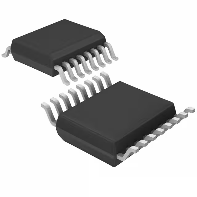
- Part No.:
- MLX90314LDF-BAA-000-RE
- Manufacturer:
- Melexis Technologies NV
- Category:
- Sensor and Detector Interfaces
- Package:
- 16-SOIC (0.295", 7.50mm Width)
- Datasheet:
-
MLX90314LDF-BAA-000-RE.pdf
- Description:
- IC SENSOR INTERFACE PROGR 16SOIC
- Quantity:
- Payment:

- Shipping:

Inventory:1,303
Please send an inquiry. Send us your inquiry, and we will respond immediately.
Product details
Overview
MLX90314LDF-BAA-000-RE from Melexis is a programmable sensor interface IC designed for bridge-type transducers, delivering microprocessor-controlled signal conditioning with 10-bit ADC/DAC, hardware gain up to 36.6 V/V, ±0.25% overall non-linearity, and support for 4–20 mA or 4–11 VDC output. It operates from 6–35 VDC supply and compensates temperature errors using internal or external sensors - deployed in automotive pressure transducers and industrial load cells.
For engineers reviewing the MLX90314LDF-BAA-000-RE datasheet, pinout, applications, or equivalent options, key selection considerations include ratiometric error tolerance (±4.6% at high gain), EEPROM-programmable temperature compensation across up to four segments, UART-based mass calibration at 2400/9600 baud, and SOIC300Mil package compatibility with ESD-sensitive handling.
Technical Context
The MLX90314LDF-BAA-000-RE integrates an LX11 RISC microcontroller core with 64 B RAM, 3 kB user firmware ROM, and 48 B EEPROM for storing gain/offset coefficients, temperature compensation parameters, and signal correction tables. Its analog signal path includes a chopper-stabilized instrumentation amplifier (CMRR ≥60 dB, hardware gain 69–84 V/V), dual coarse/fine DACs for offset and gain control, and configurable output stages supporting voltage mode (4.5–11 V) or current mode (27 mA max).
It implements temperature-stabilized clocking via a trimmed RC oscillator (87.8 kHz ±1%) with three-region digital compensation, enabling stable UART timing across −40°C to +140°C. Signal processing supports both analog mode (four-segment thermal zero/span compensation) and digital mode (five-point nonlinearity correction), with shared EEPROM allocation between temperature and signal coefficients per Table 6 of the datasheet.
Key Specifications
| Parameter | Value and Actual Design Meaning |
|---|---|
| Supply Voltage Range | 6–35 VDC unregulated input (VDD1); internal 4.75–5.2 V regulated rail (VDD) for analog circuitry |
| Operating Temperature | −40°C to +140°C ambient (TA), validated for automotive under-hood and industrial harsh environments |
| Signal Conditioning Accuracy | ±0.25% overall non-linearity after EEPROM-programmed compensation |
| ADC/DAC Resolution | 10-bit resolution for both analog-to-digital conversion and digital-to-analog output control |
| Output Configurations | Voltage mode: 4.5–6.5 V or 6.5–11 V span; current mode: 4–20 mA loop with 24 Ω sense resistor |
| UART Interface | Asynchronous serial port at 2400 baud (TURBO=0) or 9600 baud (TURBO=1), used for EEPROM programming and diagnostics |
| Bridge Input Support | Differential inputs (VBP/VBN) accepting ±2.88 to ±8.38 mV/V sensitivity, with common-mode range up to 65% VDD |
Pinout & Package
MLX90314LDF-BAA-000-RE is housed in a plastic SOIC300Mil (SO16W) package, 10.3 mm × 7.5 mm × 2.35 mm body size, with 16 leads and 1.27 mm pitch. ESD-sensitive CMOS device requiring standard handling precautions.
| Pin/Terminal | Circuit Role | Design Meaning |
|---|---|---|
| 1, 2 (I/O1, I/O2) | Bi-directional general-purpose I/O | Configurable as alarm outputs or analog inputs; controlled via firmware or UART commands |
| 3 (TSTB) | Test pin | Internal pull-up; must be tied to VDD in normal operation; used for factory test mode when pulled low |
| 4 (FLT) | Analog filter node | Connects external capacitor (e.g., 39 nF) to set signal bandwidth (2.8–4.2 kHz −3 dB point) |
| 5 (OFC) | Offset control output | Provides access to internal programmed offset voltage for external monitoring or feedback |
| 6, 7 (VBN, VBP) | Bridge differential inputs | Accept Wheatstone bridge outputs; support common-mode range up to 65% VDD |
| 8 (TMP) | Temperature sensor input | Interfaces internal or external temperature sensor (390 µV/°C sensitivity) for compensation |
| 9 (VDD) | Regulated analog supply | 4.75–5.2 V internal rail powering analog circuitry; derived from VDD1 via external FET |
| 10 (FET) | Regulator pass-FET gate drive | Drives external N-channel FET to generate stable VDD from VDD1 |
| 11 (VDD1) | Unregulated power input | Main supply (6–35 VDC) powering digital logic and FET gate driver |
| 12 (VMO) | Voltage mode output | Compensated analog voltage output (up to +11 V); sink/source capable (2 mA source, 20 µA sink) |
| 13 (CMO) | Current mode output | Compensated 4–20 mA loop output; requires external 24 Ω sense resistor |
| 14 (CMN) | Current mode return | Negative rail for current loop; connects to system ground or isolated return path |
| 15 (GND) | Power ground | Primary reference for analog/digital circuits; separate from CMN for noise isolation |
| 16 (COMS) | UART serial interface | Half-duplex bidirectional communication pin for EEPROM read/write and configuration |
Key Features
| Feature | Design Value |
|---|---|
| Programmable temperature compensation | Supports up to four independent temperature segments with dedicated offset/gain TC coefficients stored in EEPROM |
| Dual-mode signal processing | Analog mode enables thermal zero/span correction; digital mode adds five-point nonlinearity correction using programmable PCi coefficients |
| Flexible output configuration | Single device supports voltage output (4.5–11 V), current loop (4–20 mA), or simultaneous dual outputs with fault-safe defaults |
| On-chip clock stabilization | Trimmed RC oscillator (87.8 kHz ±1%) with three-region digital temperature compensation ensures UART timing stability across full operating range |
| EEPROM-based calibration | 48-byte reprogrammable EEPROM stores all compensation parameters, allowing field recalibration without hardware change |
Applications
| Pressure Transducers | Accelerometers |
|---|---|
Use Scenario: High-accuracy pressure sensing in diesel common-rail fuel systems where thermal drift must be suppressed across −40°C to +140°C. IC Role / Device Role / Timing Role: Primary signal conditioner converting millivolt-level bridge output into ratiometric 0–5 V or 4–20 mA output with real-time temperature compensation. Use Value: Reduces system-level nonlinearity to ±0.25% through EEPROM-stored four-segment thermal zero and span coefficients. | Use Scenario: Industrial vibration monitoring on rotating machinery using piezoresistive accelerometers subject to wide thermal gradients. IC Role / Device Role / Timing Role: Bridge interface IC performing gain/offset adjustment and temperature-compensated linearization before feeding data to PLC analog inputs. Use Value: Enables single-chip compensation for both thermal zero shift and thermal span shift, eliminating external calibration hardware. |
| Linear Position Sensors | Temperature Sensor Assemblies |
Use Scenario: Contactless linear position feedback in hydraulic valve spools exposed to oil immersion and thermal cycling. IC Role / Device Role / Timing Role: Programmable interface for LVDT or resistive potentiometer bridges, delivering calibrated voltage output with programmable range limiting. Use Value: Supports level steering on I/O1/I/O2 pins to indicate discrete position zones without external logic. | Use Scenario: Multi-sensor temperature monitoring in battery pack thermal management, where local bridge-based thermistor readings require precise cold-junction compensation. IC Role / Device Role / Timing Role: Dual-sensor interface accepting internal die temperature and external thermistor input for hybrid compensation modeling. Use Value: Uses internal 390 µV/°C temperature sensor plus external TMP pin to align compensation reference with physical sensor location. |
Equivalent & Alternatives
The following parts are listed as comparable options for similar programmable sensor interface applications.
| Alternative Part | Technical Difference | Application Difference | Selection Advice |
|---|---|---|---|
| MLX90316LDF-BAA-000-RE | Successor device with enhanced EEPROM layout, extended diagnostic features, and improved ESD robustness (HBM 4 kV vs. 2 kV) | Same SOIC300Mil footprint and pinout; supports identical bridge sensors but requires updated firmware for new EEPROM map | Select for new designs requiring higher reliability certification or extended diagnostics; not drop-in for legacy MLX90314 firmware |
| AD8420ARZ | Fixed-gain (10–1000 V/V) instrumentation amplifier with no onboard MCU, EEPROM, or temperature compensation logic | Requires external microcontroller, ADC, DAC, and temperature sensor for equivalent functionality; lacks UART programmability | Choose when cost-sensitive designs can implement full signal chain externally and do not require field recalibration |
Compared with MLX90314LDF-BAA-000-RE, the MLX90316 offers upgraded diagnostics and ESD rating but mandates firmware migration, while the AD8420 provides only analog amplification - requiring full external signal processing to match MLX90314LDF-BAA-000-RE's integrated programmable compensation.
Availability
MLX90314LDF-BAA-000-RE is available at Aetrix Electronics and suitable for automotive pressure transducers, industrial accelerometer interfaces, and linear position sensor modules requiring stable component supply across extended temperature ranges and long production lifecycles.
Supply support for MLX90314LDF-BAA-000-RE includes scheduled delivery planning, volume procurement assistance, BOM continuity management, traceable sourcing, and lifecycle availability coordination for OEM customers, industrial embedded developers, connected-device designers, and electronics production programs.
Manufacturer
Melexis is a Belgian semiconductor company specializing in intelligent sensor solutions for automotive, industrial, and medical markets, with expertise in magnetic, infrared, and programmable analog interfaces.
The MLX90314 product line delivers highly configurable sensor signal conditioning for bridge-based transducers, targeting applications demanding precision, thermal stability, and field-programmable calibration without external microcontrollers.
FAQ
What is the maximum operating temperature for the MLX90314LDF-BAA-000-RE?
The MLX90314LDF-BAA-000-RE is rated for continuous operation from −40°C to +140°C ambient temperature (TA), validated per its absolute maximum ratings and electrical specifications table. This range supports under-hood automotive and industrial motor-control applications. The internal temperature sensor and compensation algorithms are calibrated across this full span, and the device maintains specified performance including ±0.25% non-linearity and stable UART timing via three-region clock compensation. Always observe derating guidelines for power dissipation above 100°C.
Does the MLX90314LDF-BAA-000-RE support both voltage and current output simultaneously?
Yes, the MLX90314LDF-BAA-000-RE supports concurrent voltage and current outputs: VMO (pin 12) and CMO (pin 13) can be activated together via EEPROM configuration byte settings. When both are enabled, CMO operates at a fixed digital value defined in EEPROM bytes 28–29, while VMO delivers the primary compensated voltage output. This dual-output capability allows redundancy or cross-checking in safety-critical systems. Note that digital mode must be enabled (bit 6 of Mode Byte = 1) for simultaneous activation, and output limits remain independently programmable.
How is temperature compensation implemented in the MLX90314LDF-BAA-000-RE?
Temperature compensation in the MLX90314LDF-BAA-000-RE uses either the internal die temperature sensor (390 µV/°C) or an external sensor connected to the TMP pin. Compensation coefficients - including offset TC (OFTCi) and gain TC (GNTCi) - are stored in EEPROM and applied across up to four user-defined temperature segments. The firmware calculates real-time DAC values using linear interpolation within each segment, and the filtered temperature value (Temp_f) is computed in RAM using a first-order digital filter with user-configurable time constant (n_factor = 0–6). This architecture achieves <±0.25% residual error after calibration.
Can the MLX90314LDF-BAA-000-RE be reprogrammed in-system?
Yes, the MLX90314LDF-BAA-000-RE supports full in-system reprogramming of its 48-byte EEPROM via the COMS (pin 16) UART interface using Melexis-provided software and a simple level-shifting interface board. Parameters including gain, offset, temperature coefficients, alarm thresholds, and output ranges can be updated without removing the device from the PCB. Reprogramming requires a valid checksum (byte 47) to be written; if checksum validation fails, the device drives outputs to a user-defined fault value stored in EEPROM bytes 40–41. No special voltage or timing sequences are needed beyond standard UART handshaking.
What package type does the MLX90314LDF-BAA-000-RE use, and are there layout considerations?
The MLX90314LDF-BAA-000-RE uses a plastic SOIC300Mil (SO16W) package measuring 10.3 mm × 7.5 mm × 2.35 mm with 1.27 mm lead pitch. Layout best practices include separating analog (VDD, VBP/VBN, FLT, TMP) and digital (VDD1, COMS, TSTB) power domains with dedicated ground planes, placing a 100 nF ceramic decoupling capacitor close to VDD and VDD1 pins, routing the FLT pin to a 39 nF capacitor for 3.5 kHz bandwidth control, and guarding the VBP/VBN traces against noise. As an ESD-sensitive CMOS device, it requires handling per ANSI/ESD S20.20 and PCB layout should avoid floating pins - especially TSTB (pin 3), which must be tied to VDD.
MLX90314LDF-BAA-000-RE Specifications
- Product attributes
- Attribute value
- Manufacturer:
- Melexis Technologies NV
- Package/Case:
- 16-SOIC (0.295", 7.50mm Width)
- Series:
- -
- Packaging:
- Tape & Reel (TR)
- Product Status:
- Obsolete
- Programmable:
- Not Verified
- Type:
- Signal Conditioner
- Input Type:
- -
- Output Type:
- -
- Current - Supply:
- -
- Operating Temperature:
- -
- Grade:
- -
- Qualification:
- -
- Mounting Type:
- Surface Mount
- Supplier Device Package:
- 16-SOIC
MLX90314LDF-BAA-000-RE FAQ
1.How can I place an order for MLX90314LDF-BAA-000-RE through Aetrix?
Please submit a Request for Quotation (RFQ) for MLX90314LDF-BAA-000-RE on Aetrix. Our sales agent will provide a competitive quotation and guide you through the order confirmation once you accept the terms.
2.Are the price and stock information for MLX90314LDF-BAA-000-RE reliable?
The price and inventory of MLX90314LDF-BAA-000-RE are updated periodically and may fluctuate due to market conditions. Stock and pricing data are typically refreshed every 24 hours. Quotation validity for MLX90314LDF-BAA-000-RE is usually 5 days.
3.What payment methods are accepted for MLX90314LDF-BAA-000-RE?
We accept Wire Transfer, PayPal, Credit Card, Western Union, MoneyGram, and Escrow for MLX90314LDF-BAA-000-RE transactions.
Note: Certain payment methods may incur a processing fee.
4.How is shipping managed for MLX90314LDF-BAA-000-RE?
MLX90314LDF-BAA-000-RE orders can be shipped via leading logistics carriers, including DHL, UPS, FedEx, TNT, or Registered Mail.
Once your MLX90314LDF-BAA-000-RE order is processed, you will receive an email with the shipment details and tracking number.
Note: Tracking information may take up to 24 hours to appear. Express delivery typically takes 3–5 business days.
5.How can I obtain technical support or documentation for MLX90314LDF-BAA-000-RE?
For technical support, including MLX90314LDF-BAA-000-RE datasheets, pinout diagrams, or application guidance, please contact our engineering support team. They can provide detailed documentation and assistance for your MLX90314LDF-BAA-000-RE requirements.
6.How does Aetrix verify that MLX90314LDF-BAA-000-RE is sourced from the original manufacturer or authorized distributors?
All MLX90314LDF-BAA-000-RE products on Aetrix are procured from qualified distributors and authorized channels. Our dedicated quality assurance team conducts strict verification, including traceability checks and, if necessary, third-party testing. This ensures that MLX90314LDF-BAA-000-RE meets industry standards.
7.What is the process for return or replacement of MLX90314LDF-BAA-000-RE?
All MLX90314LDF-BAA-000-RE units undergo pre-shipment inspection (PSI). If there is an issue with MLX90314LDF-BAA-000-RE, returns or replacements are accepted under the following conditions:
1.Quantity discrepancies, incorrect items, or visible external defects (such as breakage or corrosion), acknowledged by Aetrix.
2.The issue is reported within 90 days of delivery.
3.The MLX90314LDF-BAA-000-RE part is unused and in its original packaging.
Return procedure for MLX90314LDF-BAA-000-RE:
1.Submit a request within 90 days.
2.Obtain a Return Material Authorization (RMA) from Aetrix.
MLX90314LDF-BAA-000-RE Tags

-
RE46C100S8TF
Microchip Technology

-
XTR111AIDRCR
Texas Instruments

-
XTR111AIDGQR
Texas Instruments

-
XTR117AIDGKR
Texas Instruments

-
XTR111AIDGQT
Texas Instruments

-
XTR115UA/2K5
Texas Instruments

-
MAX14626ETT+T
Analog Devices Inc./Maxim Integrated

-
XTR116UA/2K5
Texas Instruments

-
XTR115U/2K5
Texas Instruments

-
XTR116U/2K5
Texas Instruments

-
PGA308AIDGSR
Texas Instruments

-
XTR300AIRGWR
Texas Instruments
Tech Hub

Comparator circuit design covering voltage thresholds, input limits, open-collector outputs, LM393 wiring, op-amp differences, hysteresis, timing, window detection and practical fault diagnosis.
Schmitt triggers use separate rising and falling thresholds to stabilize slow or noisy signals. This guide covers hysteresis, 74HC14 and 74HCT14 selection, comparator calculations, RC oscillators and p…
Counterfeit components can hide behind convincing markings and passing basic function tests. This engineering reference covers source traceability, external inspection, X-ray, XRF, electrical testing, …
A practical engineering and sourcing framework covering lifecycle verification, lifetime-buy calculations, replacement qualification, supplier checks and counterfeit-risk controls.
TTL and CMOS logic families differ in thresholds, loading, output drive, power and timing. This engineering guide compares 74HC and 74HCT, calculates noise margins and checks 3.3 V/5 V compatibility.
A practical engineering guide to 3.3V and 5V logic compatibility, input thresholds, resistor dividers, translator ICs, MOSFET level shifting, I2C pull-ups, timing limits and power-sequencing risks.
The 74HC595 uses push-pull logic outputs, while the TPIC6B595 uses 50 V open-drain DMOS sinks for higher-power loads. This guide compares timing, current limits, 3.3 V interfacing, load wiring, thermal…
The 74HC595 converts serial data into eight stable parallel outputs. This guide covers pin functions, shift and storage timing, OE and MR behavior, drive-current limits, cascading, voltage compatibilit…
A technical comparison of level-sensitive latches and edge-triggered flip-flops, covering timing windows, setup and hold limits, master–slave operation, time borrowing, race-through, HDL inference and…
A D latch stores one bit while Enable controls when data can pass. This reference covers gate-level operation, truth tables, transparency, setup and hold timing, LE versus OE, common ICs and practical …










