
 My Inquiry
 My Account


Infineon Technologies PEB20550HV1.3
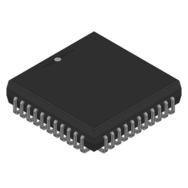
- Part No.:
- PEB20550HV1.3
- Manufacturer:
- Infineon Technologies
- Category:
- Application Specific Microcontrollers
- Package:
- -
- Datasheet:
-
 PEB20550HV1.3.pdf
- Description:
- ELIC EXTENDED LINE CARD INTERFAC
- Quantity:
- Payment:

- Shipping:

Inventory:117
Please send an inquiry. Send us your inquiry, and we will respond immediately.
Product details
Overview
PEB20550HV1.3 from Infineon Technologies is a high-voltage, dual-channel gate driver IC designed for driving N-channel power MOSFETs and IGBTs in half-bridge configurations. It features 600 V high-side floating capability, ±2.5 A peak output current per channel, and integrated bootstrap diode. It is used in industrial motor drives and switched-mode power supplies.
For engineers reviewing the PEB20550HV1.3 datasheet, PEB20550HV1.3 pinout, PEB20550HV1.3 application, or PEB20550HV1.3 equivalent, key selection criteria include high-side voltage rating, propagation delay matching between channels, undervoltage lockout thresholds, and thermal shutdown behavior under continuous switching conditions.
Technical Context
The PEB20550HV1.3 integrates independent high-side and low-side drivers with matched propagation delays (typ. 190 ns) and fast rise/fall times (typ. 45 ns/35 ns). It uses level-shifting circuitry to enable operation of the high-side driver up to 600 V referenced to ground.
It includes non-latching UVLO on both channels (VCC: 10–18 V, VBS: 9–16 V), built-in dead-time generation (typ. 450 ns), and thermal shutdown at 150 °C. No external bootstrap capacitor is required due to the integrated diode.
Key Specifications
| Parameter | Value and Actual Design Meaning |
|---|---|
| High-side voltage rating | 600 V - supports direct connection to high-voltage DC bus in half-bridge topologies |
| Peak output current | ±2.5 A - sufficient to drive large gate capacitance of 650 V IGBTs within safe SOA |
| Propagation delay match | ±10 ns - ensures precise timing alignment critical for minimizing shoot-through risk |
| UVLO threshold (VBS) | 9 V (on), 7.5 V (off) - prevents erratic switching during bootstrap capacitor discharge |
| Thermal shutdown | 150 °C - protects internal driver stages from irreversible junction overheating |
| Operating temperature | −40 °C to +125 °C - qualified for industrial ambient environments |
Pinout & Package
PEB20550HV1.3 is housed in a 16-pin SOIC wide-body package (SO-16W) with creepage distance >8 mm for reinforced insulation.
| Pin/Terminal | Circuit Role | Design Meaning |
|---|---|---|
| VDD | Low-side supply input | Provides power to low-side driver stage; must be decoupled with ≥1 μF ceramic capacitor |
| VBS | Bootstrap supply input | Connects to bootstrap capacitor; enables high-side floating operation up to 600 V |
| HIN | High-side input | TTL/CMOS-compatible logic input controlling high-side output; 3.3 V/5 V compatible |
| LIN | Low-side input | TTL/CMOS-compatible logic input controlling low-side output; inverted logic optional via external resistor |
| HOUT | High-side output | Drives gate of high-side N-channel device; capable of sourcing/sinking ±2.5 A |
| LOUT | Low-side output | Drives gate of low-side N-channel device; matched delay and drive strength to HOUT |
| VSS | Power ground | Reference for low-side driver and logic inputs; separate from high-side floating ground |
| COM | High-side floating ground | Return path for high-side driver; tied to source of high-side switch in half-bridge layout |
Key Features
| Feature | Design Value |
|---|---|
| Integrated bootstrap diode | Eliminates need for external diode, reducing BOM count and PCB footprint in compact SMPS designs |
| Matched propagation delay | Ensures <10 ns skew between HIN→HOUT and LIN→LOUT paths, enabling reliable dead-time control |
| Non-latching UVLO | Prevents unintended turn-on during brown-out; resumes normal operation automatically after recovery |
| Thermal shutdown with hysteresis | Shuts down at 150 °C and re-enables only after cooling to 135 °C, avoiding oscillatory restart |
Applications
| Industrial Motor Drives | Server PSU Half-Bridge |
|---|---|
Use Scenario: 3-phase inverter stage in 1–5 kW servo drives operating from 400 V DC bus. IC Role / Device Role / Timing Role: Dual gate driver providing synchronized, high-current gate signals to upper/lower IGBTs in each leg. Use Value: 600 V high-side rating and matched delays reduce risk of shoot-through and improve system efficiency at 20 kHz switching. | Use Scenario: Primary-side half-bridge in 80+ Titanium-rated 1.5 kW server power supplies. IC Role / Device Role / Timing Role: Gate driver for 650 V Si MOSFETs in resonant LLC topology with ZVS operation. Use Value: Integrated bootstrap diode simplifies layout and improves reliability over discrete solutions in high-density PSU modules. |
| Solar Microinverters | EV Onboard Charger |
Use Scenario: Full-bridge inverter stage converting DC from PV panel to 230 V AC grid interface. IC Role / Device Role / Timing Role: High-side/low-side driver for 600 V GaN FETs in interleaved full-bridge configuration. Use Value: 150 °C thermal shutdown and −40 °C start-up support operation in outdoor enclosures with minimal heatsinking. | Use Scenario: Secondary-side synchronous rectification driver in 6.6 kW bidirectional OBC using SiC MOSFETs. IC Role / Device Role / Timing Role: Low-latency gate driver enabling precise phase-shift control in dual-active-bridge topology. Use Value: ±10 ns propagation delay match ensures accurate zero-voltage switching across wide load and temperature ranges. |
Equivalent & Alternatives
The following parts are listed as comparable options for similar high-voltage dual gate driver applications.
| Alternative Part | Technical Difference | Application Difference | Selection Advice |
|---|---|---|---|
| IR2110STRPBF | Higher propagation delay (340 ns), no integrated bootstrap diode, lower peak current (±2 A) | Requires external bootstrap diode and larger gate resistors for same switching speed | Preferred where cost sensitivity outweighs layout density and thermal margin requirements |
| UCC27211D | Lower high-side voltage rating (200 V), no bootstrap diode, higher drive current (±4 A) | Limited to low-voltage half-bridges (e.g., 12–48 V DC bus); unsuitable for 400 V+ systems | Selected when driving low-RDS(on) MOSFETs at high frequency in low-voltage industrial controls |
Compared with IR2110STRPBF and UCC27211D, PEB20550HV1.3 uniquely combines 600 V high-side capability, integrated bootstrap diode, and sub-200 ns matched delays-enabling compact, robust half-bridge designs in 400–600 V industrial and renewable energy systems without external level-shift components.
Availability
PEB20550HV1.3 is available at Aetrix Electronics and suitable for industrial motor drives, solar microinverters, and EV onboard chargers requiring stable component supply and long-term production continuity.
Supply support for PEB20550HV1.3 includes scheduled delivery planning, volume procurement assistance, BOM continuity management, traceable sourcing, and lifecycle availability coordination for OEM customers, industrial embedded developers, connected-device designers, and electronics production programs.
Manufacturer
Infineon Technologies is a German semiconductor manufacturer specializing in power semiconductors, microcontrollers, and sensor solutions for industrial, automotive, and renewable energy markets.
The EiceDRIVER™ family, including PEB20550HV1.3, is engineered for high-reliability gate driving in high-voltage power conversion systems with emphasis on timing precision, isolation integrity, and thermal resilience.
FAQ
What is the minimum recommended bootstrap capacitor value for PEB20550HV1.3?
The datasheet specifies a minimum 100 nF ceramic capacitor between VBS and COM, rated for ≥25 V with X7R dielectric. For 20 kHz operation with 50% duty cycle and 2.5 A peak gate charge, a 220 nF/50 V capacitor is recommended to maintain VBS above 9 V under worst-case load transients.
Does PEB20550HV1.3 support 3.3 V logic inputs?
Yes, PEB20550HV1.3 accepts TTL- and CMOS-compatible logic levels: HIN and LIN inputs recognize voltages ≥2.0 V as high and ≤0.8 V as low. It operates reliably with 3.3 V microcontroller outputs without level shifting, provided VDD is ≥10 V.
Can PEB20550HV1.3 drive SiC MOSFETs directly?
Yes, its ±2.5 A peak output current and fast 45 ns/35 ns rise/fall times meet gate drive requirements for common 650 V SiC MOSFETs (e.g., IMW120R045M1H) with Qg ≤ 35 nC. Layout must minimize source inductance to avoid ringing during hard switching.
Is there an evaluation board available for PEB20550HV1.3?
Infineon offers the EVAL-PED20550HV13 evaluation board (order code EVAL-PED20550HV13), which implements a half-bridge test fixture with Kelvin gate connections, adjustable dead time, and thermal monitoring. It supports direct probing of HOUT/LOUT waveforms and bootstrap node stability analysis.
PEB20550HV1.3 Specifications
- Product attributes
- Attribute value
- Manufacturer:
- Infineon Technologies
- Series:
- *
- Package/Case:
- -
- Packaging:
- Bulk
- Product Status:
- Active
- Programmable:
- Not Verified
- Applications:
- -
- Core Processor:
- -
- Program Memory Type:
- -
- Controller Series:
- -
- RAM Size:
- -
- Interface:
- -
- Number of I/O:
- -
- Voltage - Supply:
- -
- Operating Temperature:
- -
- Grade:
- -
- Qualification:
- -
- Mounting Type:
- -
- Supplier Device Package:
- -
PEB20550HV1.3 FAQ
1.How can I place an order for PEB20550HV1.3 through Aetrix?
Please submit a Request for Quotation (RFQ) for PEB20550HV1.3 on Aetrix. Our sales agent will provide a competitive quotation and guide you through the order confirmation once you accept the terms.
2.Are the price and stock information for PEB20550HV1.3 reliable?
The price and inventory of PEB20550HV1.3 are updated periodically and may fluctuate due to market conditions. Stock and pricing data are typically refreshed every 24 hours. Quotation validity for PEB20550HV1.3 is usually 5 days.
3.What payment methods are accepted for PEB20550HV1.3?
We accept Wire Transfer, PayPal, Credit Card, Western Union, MoneyGram, and Escrow for PEB20550HV1.3 transactions.
Note: Certain payment methods may incur a processing fee.
4.How is shipping managed for PEB20550HV1.3?
PEB20550HV1.3 orders can be shipped via leading logistics carriers, including DHL, UPS, FedEx, TNT, or Registered Mail.
Once your PEB20550HV1.3 order is processed, you will receive an email with the shipment details and tracking number.
Note: Tracking information may take up to 24 hours to appear. Express delivery typically takes 3–5 business days.
5.How can I obtain technical support or documentation for PEB20550HV1.3?
For technical support, including PEB20550HV1.3 datasheets, pinout diagrams, or application guidance, please contact our engineering support team. They can provide detailed documentation and assistance for your PEB20550HV1.3 requirements.
6.How does Aetrix verify that PEB20550HV1.3 is sourced from the original manufacturer or authorized distributors?
All PEB20550HV1.3 products on Aetrix are procured from qualified distributors and authorized channels. Our dedicated quality assurance team conducts strict verification, including traceability checks and, if necessary, third-party testing. This ensures that PEB20550HV1.3 meets industry standards.
7.What is the process for return or replacement of PEB20550HV1.3?
All PEB20550HV1.3 units undergo pre-shipment inspection (PSI). If there is an issue with PEB20550HV1.3, returns or replacements are accepted under the following conditions:
1.Quantity discrepancies, incorrect items, or visible external defects (such as breakage or corrosion), acknowledged by Aetrix.
2.The issue is reported within 90 days of delivery.
3.The PEB20550HV1.3 part is unused and in its original packaging.
Return procedure for PEB20550HV1.3:
1.Submit a request within 90 days.
2.Obtain a Return Material Authorization (RMA) from Aetrix.
PEB20550HV1.3 Tags

-
CYPD3175-24LQXQ
Infineon Technologies

-
SLB9672VU20FW1523XTMA1
Infineon Technologies

-
SLB9670VQ20FW785XTMA1
Infineon Technologies
-
SLB9672XU20FW1523XTMA1
Infineon Technologies
-
SLB9673XU20FW2613XTMA1
Infineon Technologies

-
CYPD3125-40LQXIT
Infineon Technologies

-
AT97SC3204-U2A1A-20
Microchip Technology
-
AT97SC3204-U2A1A-10
Microchip Technology
-
SLM9670AQ20FW1311XTMA1
Infineon Technologies
-
SLB9672XU20FW1613XTMA1
Infineon Technologies
-
SLB9672AU20FW1613XTMA1
Infineon Technologies
-
SLB9673AU20FW2613XTMA1
Infineon Technologies
Tech Hub

18650 battery guide covering lithium-ion cell basics, 3.6V/3.7V voltage, 4.2V charging, mAh and Wh capacity, protected cells, chargers, BMS, series-parallel packs, holders, welding and sourcing checks.…

Hall effect sensor guide covering working principle, linear and digital sensors, Arduino circuits, current sensing, speed detection, automotive applications, A3144 examples, signal filtering and datash…

Product Change Notification guide for electronic components, covering PCN meaning, PCN vs PDN/EOL, common change types, risk levels, form-fit-function review, engineering validation, BOM control, LTB/L…

A practical guide to blend door actuators, covering HVAC function, symptoms, location, AC and heater issues, reset and calibration, replacement cost, electrical diagnosis, compatibility checks, and rep…

Engineering guide to Raspberry Pi alternatives, covering chip-level differences, Orange Pi, ROCK, Jetson, Banana Pi, NanoPi, Compute Module, Pico, GPIO, camera, HAT compatibility, and replacement risks…

Engineering guide to dynamic load response testing for high-current buck converters, covering load step setup, slew rate, Vcore undershoot, overshoot, recovery time, probe location, output capacitors a…

Engineering guide to output capacitor selection for ASIC Vcore rails, covering bulk capacitors, polymer capacitors, MLCC decoupling, DC bias, ESR, ESL, placement, transient response and substitution ri…

Engineering guide to high-current ASIC Vcore rails, covering 12-phase buck architecture, PMBus control, dynamic load testing, output capacitor networks, smart power stage selection, thermal design and …

Voltage regulator guide covering linear, LDO, 7805, Zener, adjustable, buck, VRM and alternator regulators, with design checks, testing methods, troubleshooting and datasheet-based selection.

Amplifier guide covering voltage, current and power amplification, gain, feedback, amplifier classes, audio and RF applications, op-amp circuits, transimpedance amplifiers, datasheet selection and trou…


