Qorvo QPC3223TR7
- Part No.:
- QPC3223TR7
- Manufacturer:
- Qorvo
- Category:
- Attenuators
- Package:
- 12-VFQFN Exposed Pad
- Datasheet:
-
QPC3223TR7.pdf
- Description:
- 50-6000MHZ 2-BIT, 18DB RANGE DSA
- Quantity:
- Payment:

- Shipping:

Inventory:1,899
Please send an inquiry. Send us your inquiry, and we will respond immediately.
Product details
Overview
QPC3223TR7 from Qorvo is a 2-bit digital step attenuator (DSA) operating from 50 MHz to 6000 MHz, delivering 18 dB attenuation range in precise 6 dB steps with 0.8 dB insertion loss at 2 GHz and input IP3 > +55 dBm. It uses a parallel control interface, supports 1.8 V logic compatibility, and is deployed in RF front-ends of Wi-Fi access points and 4G base station transceivers.
For engineers reviewing the QPC3223TR7 datasheet, pinout, applications, or equivalent options, key selection criteria include its overshoot-free transient switching performance, single 3–5 V supply operation, and DC-groundable RF pins enabling simplified biasing in compact RF layouts.
Technical Context
The QPC3223TR7 implements a patented monolithic GaAs pHEMT circuit architecture optimized for broadband RF signal conditioning. Its 2-bit parallel interface directly controls four discrete attenuation states (0/6/12/18 dB), with power-up default set to maximum attenuation (18 dB).
Transient switching is overshoot-free due to internal charge-balanced switching topology, and RF ports are internally DC-grounded via resistors-enabling external DC grounding without blocking RF paths. Thermal resistance is 62 °C/W at max attenuation under RF load.
Key Specifications
| Parameter | Value and Actual Design Meaning |
|---|---|
| Frequency Range | 50 MHz to 6000 MHz - fully specified performance across sub-1 GHz through 6 GHz bands including LTE, Wi-Fi 5/6, and point-to-point links. |
| Attenuation Range & Step | 18 dB total range in 6 dB increments - enables coarse gain control with minimal state transitions and predictable inter-stage isolation. |
| Insertion Loss | 0.8 dB at 2 GHz - low path loss preserves system noise figure and output power efficiency in cascaded RF chains. |
| Input IP3 | +55 dBm - high linearity prevents distortion in multi-tone environments like OFDMA-based 4G/5G uplinks and Wi-Fi APs. |
| Switching Speed | 80 ns typical - fast settling supports dynamic TDD frame-level attenuation updates without transient glitches. |
| Supply Voltage | +3 V to +5 V - compatible with standard RF subsystem rails and eliminates need for dedicated low-noise LDOs. |
| Logic Compatibility | 1.8 V CMOS - interfaces directly with FPGA I/O banks and baseband processors without level-shifting circuitry. |
Pinout & Package
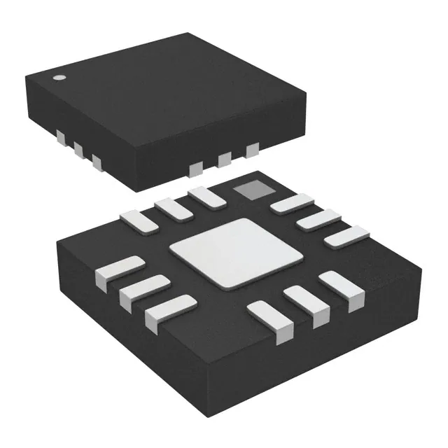
QPC3223TR7 is housed in a lead-free, RoHS-compliant 12-pad 3.0 mm × 3.0 mm QFN package with exposed backside ground pad for thermal and RF grounding.
| Pin/Terminal | Circuit Role | Design Meaning |
|---|---|---|
| 1, 9, Backside Pad | GND | RF/DC ground reference; backside pad requires ≥4 thermal vias to inner ground plane for optimal thermal dissipation and impedance stability. |
| 2 | RFIN | RF input port; incident signal must enter here for rated thermal reliability; DC voltage prohibited; may be externally DC grounded. |
| 8 | RFOUT | RF output port; may be externally DC grounded; internal resistor network ensures stable DC bias under all attenuation states. |
| 10, 11 | C2, C1 | Parallel control inputs (12 dB and 6 dB bits); 1.8 V CMOS-compatible; logic high = H, logic low = L per truth table. |
| 12 | VDD | Single positive supply input (+3 V to +5 V); decoupling capacitor (≥1 µF X7R) required within 2 mm of pin. |
| 3–7 | NC | No-connect pads; recommended to tie to PCB ground for mechanical stability and EMI suppression. |
Key Features
| Feature | Design Value |
|---|---|
| Overshoot-free transient switching | Eliminates RF output glitches during attenuation state changes-critical for TDD systems and burst-mode test equipment. |
| DC-groundable RF pins | Enables direct connection of RFIN/RFOUT to PCB ground planes without blocking RF paths, simplifying matching network layout. |
| Power-up default = 18 dB | Ensures fail-safe RF signal suppression at startup-prevents uncontrolled transmission in powered-up but uninitialized systems. |
| High input IP3 (> +55 dBm) | Maintains signal integrity in high-power multi-carrier scenarios such as macrocell base station transmit chains. |
| Low steady-state current (180 µA) | Minimizes quiescent power draw in battery-backed or energy-constrained RF modules and portable test gear. |
Applications
| Wi-Fi 6 Access Points | 4G LTE Base Stations |
|---|---|
Use Scenario: Dynamic uplink power control in MU-MIMO APs to maintain per-client SNR while avoiding adjacent-channel interference. IC Role / Device Role / Timing Role: Digital step attenuator in the transmit signal path, controlled by baseband processor via parallel bus on frame boundary. Use Value: 6 dB step resolution enables precise per-client gain adjustment; 80 ns switching ensures no frame corruption during rapid channel reassignment. | Use Scenario: Output power leveling across multiple RF carriers in remote radio heads (RRHs) supporting 2×20 MHz LTE aggregation. IC Role / Device Role / Timing Role: Front-end attenuator placed after PA driver stage to manage composite output power before final PA and filter stages. Use Value: +55 dBm IP3 prevents intermodulation distortion between aggregated carriers; 50–6000 MHz bandwidth covers all LTE Band 1–41 deployments. |
| Point-to-Point Microwave Radios | RF Test Equipment |
Use Scenario: Automatic gain control (AGC) loop element in licensed 5–24 GHz backhaul radios compensating for variable path loss over distance and weather. IC Role / Device Role / Timing Role: Closed-loop attenuator in IF or RF path, updated every 10–100 ms based on RSSI feedback from demodulator. Use Value: Overshoot-free switching prevents AGC-induced transient spurs; 18 dB range accommodates >30 dB fade margin in rain fade conditions. | Use Scenario: Programmable loss calibration stage in vector network analyzers (VNAs) and signal generators requiring traceable, repeatable attenuation steps. IC Role / Device Role / Timing Role: Precision DSA in instrument's internal reference path, controlled via microcontroller parallel interface during self-calibration routines. Use Value: ±(0.2 + 4% of setting) accuracy enables NIST-traceable loss verification; 0.8 dB insertion loss minimizes calibration uncertainty floor. |
Equivalent & Alternatives
The following parts are listed as comparable options for similar digital step attenuator applications.
| Alternative Part | Technical Difference | Application Difference | Selection Advice |
|---|---|---|---|
| QPC3222TR7 | Same 50–6000 MHz range and 6 dB step, but 12 dB max attenuation and lower IP3 (+52 dBm). | Suitable for lower-power receivers or intermediate gain stages where full 18 dB range is unnecessary. | Select QPC3222TR7 only if system-level attenuation budget allows ≤12 dB and linearity requirements are relaxed. |
| ADL5240ACPZ-R7 | 3-bit DSA (24 dB range, 3 dB steps), 700–3800 MHz range, higher supply current (3.5 mA), SPI interface only. | Better suited for wide-dynamic-range cellular infrastructure where finer step resolution and SPI integration are prioritized over broadband coverage. | Choose ADL5240ACPZ-R7 when 3 dB granularity and SPI control are mandatory, and frequency coverage beyond 3.8 GHz is not required. |
Compared with QPC3223TR7, QPC3222TR7 offers reduced range and linearity for cost-sensitive receiver paths, while ADL5240ACPZ-R7 trades broadband operation and parallel simplicity for finer resolution and serial programmability-making QPC3223TR7 optimal for wideband, low-glitch, parallel-controlled transmit applications.
Availability
QPC3223TR7 is available at Aetrix Electronics and suitable for Wi-Fi 6 access points, 4G LTE base stations, and RF test equipment requiring stable component supply, consistent RF performance across temperature, and long-term production continuity.
Supply support for QPC3223TR7 includes scheduled delivery planning, volume procurement assistance, BOM continuity management, traceable sourcing, and lifecycle availability coordination for OEM customers, industrial embedded developers, connected-device designers, and electronics production programs.
Manufacturer
Qorvo is a U.S.-based semiconductor company specializing in RF solutions for mobile, infrastructure, and defense markets, with leadership in GaAs and SOI process technologies.
The QPC3223TR7 belongs to Qorvo's broadband digital step attenuator product line, engineered for high-linearity, low-distortion RF signal conditioning in wireless infrastructure and instrumentation where wideband operation and glitch-free switching are essential.
FAQ
What is the power-up default attenuation state of the QPC3223TR7?
The QPC3223TR7 powers up in the maximum attenuation state (18 dB) when VDD is applied. This fail-safe behavior suppresses RF output until the host controller asserts valid logic levels on C1 and C2 pins. To initialize to another state, apply the corresponding parallel control bits (e.g., C1=L, C2=L for 0 dB) before or simultaneously with VDD ramp-up. The QPC3223TR7 does not retain state across power cycles.
Can the RFIN and RFOUT pins of the QPC3223TR7 be DC grounded externally?
Yes, both RFIN and RFOUT pins of the QPC3223TR7 may be DC grounded externally because they contain internal resistive grounding networks. This eliminates the need for DC-blocking capacitors in many designs, simplifying layout and preserving low-frequency response. However, no DC voltage must be applied to RFIN-only RF signals-and the device must operate within its absolute maximum input power ratings (+27 dBm at +85°C case temperature).
What is the minimum and maximum supply voltage for reliable operation of the QPC3223TR7?
The QPC3223TR7 operates reliably with a supply voltage (VDD) ranging from +2.7 V to +5.5 V, though the recommended operating range is +3.0 V to +5.0 V per datasheet specifications. Operation below +2.7 V risks incomplete logic threshold compliance and degraded RF performance; above +5.5 V violates absolute maximum rating and may cause permanent damage. The QPC3223TR7 draws only 180 µA in steady state across this full voltage range.
How does the QPC3223TR7 achieve overshoot-free transient switching?
The QPC3223TR7 achieves overshoot-free transient switching through a patented charge-balanced switching architecture that equalizes charge injection across all transistor gates during state transitions. This eliminates voltage spikes and ringing at RFOUT, critical for TDD systems and burst-mode instruments. Measured switching time is 80 ns (50% CTL to 10%/90% RF), and the QPC3223TR7 maintains this performance across its full 50–6000 MHz band and −40°C to +105°C case temperature range.
Is the QPC3223TR7 pin-compatible with other devices in Qorvo's QPC32xx family?
No, the QPC3223TR7 is not pin-compatible with other QPC32xx variants such as QPC3222TR7 or QPC3224TR7-their pin assignments differ significantly, particularly for control inputs and ground distribution. While all share the same 3 mm × 3 mm QFN package footprint, the QPC3223TR7 uses C1/C2 on pins 11/10 for parallel control, whereas QPC3222TR7 repurposes those pins for different functions. PCB layout must be designed specifically for QPC3223TR7.
QPC3223TR7 Specifications
- Product attributes
- Attribute value
- Manufacturer:
- Qorvo
- Package/Case:
- 12-VFQFN Exposed Pad
- Series:
- -
- Packaging:
- Tape & Reel (TR)
- Product Status:
- Active
- Attenuation Value:
- 0dB
- Frequency Range:
- 50 MHz ~ 6 GHz
- Power (Watts):
- -
- Impedance:
- 50 Ohms
- Grade:
- -
- Qualification:
- -
QPC3223TR7 FAQ
1.How can I place an order for QPC3223TR7 through Aetrix?
Please submit a Request for Quotation (RFQ) for QPC3223TR7 on Aetrix. Our sales agent will provide a competitive quotation and guide you through the order confirmation once you accept the terms.
2.Are the price and stock information for QPC3223TR7 reliable?
The price and inventory of QPC3223TR7 are updated periodically and may fluctuate due to market conditions. Stock and pricing data are typically refreshed every 24 hours. Quotation validity for QPC3223TR7 is usually 5 days.
3.What payment methods are accepted for QPC3223TR7?
We accept Wire Transfer, PayPal, Credit Card, Western Union, MoneyGram, and Escrow for QPC3223TR7 transactions.
Note: Certain payment methods may incur a processing fee.
4.How is shipping managed for QPC3223TR7?
QPC3223TR7 orders can be shipped via leading logistics carriers, including DHL, UPS, FedEx, TNT, or Registered Mail.
Once your QPC3223TR7 order is processed, you will receive an email with the shipment details and tracking number.
Note: Tracking information may take up to 24 hours to appear. Express delivery typically takes 3–5 business days.
5.How can I obtain technical support or documentation for QPC3223TR7?
For technical support, including QPC3223TR7 datasheets, pinout diagrams, or application guidance, please contact our engineering support team. They can provide detailed documentation and assistance for your QPC3223TR7 requirements.
6.How does Aetrix verify that QPC3223TR7 is sourced from the original manufacturer or authorized distributors?
All QPC3223TR7 products on Aetrix are procured from qualified distributors and authorized channels. Our dedicated quality assurance team conducts strict verification, including traceability checks and, if necessary, third-party testing. This ensures that QPC3223TR7 meets industry standards.
7.What is the process for return or replacement of QPC3223TR7?
All QPC3223TR7 units undergo pre-shipment inspection (PSI). If there is an issue with QPC3223TR7, returns or replacements are accepted under the following conditions:
1.Quantity discrepancies, incorrect items, or visible external defects (such as breakage or corrosion), acknowledged by Aetrix.
2.The issue is reported within 90 days of delivery.
3.The QPC3223TR7 part is unused and in its original packaging.
Return procedure for QPC3223TR7:
1.Submit a request within 90 days.
2.Obtain a Return Material Authorization (RMA) from Aetrix.
QPC3223TR7 Tags

-
PAT0510S-C-3DB-T10
Susumu

-
PAT0510S-C-10DB-T10
Susumu

-
PAT0510S-C-2DB-T10
Susumu
-
PAT1220-C-10DB-T5
Susumu

-
PAT1220-C-6DB-T5
Susumu

-
PAT1220-C-0DB-T5
Susumu

-
PAT1220-C-3DB-T5
Susumu

-
PAT1220-C-5DB-T5
Susumu

-
PAT1220-C-8DB-T5
Susumu
-
MAADSS0008TR-3000
MACOM Technology Solutions

-
MAATSS0018TR-3000
MACOM Technology Solutions
-
PE43205B-Z
pSemi
Tech Hub

Comparator circuit design covering voltage thresholds, input limits, open-collector outputs, LM393 wiring, op-amp differences, hysteresis, timing, window detection and practical fault diagnosis.
Schmitt triggers use separate rising and falling thresholds to stabilize slow or noisy signals. This guide covers hysteresis, 74HC14 and 74HCT14 selection, comparator calculations, RC oscillators and p…
Counterfeit components can hide behind convincing markings and passing basic function tests. This engineering reference covers source traceability, external inspection, X-ray, XRF, electrical testing, …
A practical engineering and sourcing framework covering lifecycle verification, lifetime-buy calculations, replacement qualification, supplier checks and counterfeit-risk controls.
TTL and CMOS logic families differ in thresholds, loading, output drive, power and timing. This engineering guide compares 74HC and 74HCT, calculates noise margins and checks 3.3 V/5 V compatibility.
A practical engineering guide to 3.3V and 5V logic compatibility, input thresholds, resistor dividers, translator ICs, MOSFET level shifting, I2C pull-ups, timing limits and power-sequencing risks.
The 74HC595 uses push-pull logic outputs, while the TPIC6B595 uses 50 V open-drain DMOS sinks for higher-power loads. This guide compares timing, current limits, 3.3 V interfacing, load wiring, thermal…
The 74HC595 converts serial data into eight stable parallel outputs. This guide covers pin functions, shift and storage timing, OE and MR behavior, drive-current limits, cascading, voltage compatibilit…
A technical comparison of level-sensitive latches and edge-triggered flip-flops, covering timing windows, setup and hold limits, master–slave operation, time borrowing, race-through, HDL inference and…
A D latch stores one bit while Enable controls when data can pass. This reference covers gate-level operation, truth tables, transparency, setup and hold timing, LE versus OE, common ICs and practical …









