Send an Inquiry

To receive a quote for your project, please fill in the following information, and we’ll get back to you promptly.

Name*
Company*
Email Address*
Phone/WhatsApp
Part Number*
Quantity*
Message
Submit Inventory List

Please fill in the following information, and we’ll get back to you promptly.

Name*
Company*
Email Address*
Phone/WhatsApp
Upload My List
Message

Qorvo QPC4614TR13

Part No.:
QPC4614TR13
Manufacturer:
Qorvo
Category:
Attenuators
Package:
20-VFQFN Exposed Pad
Datasheet:
AetrixQPC4614TR13.pdf
Description:
75-OHM, 6-BIT, 0.5DB STEP, SERIA
Quantity:
Payment:
Payment
Shipping:
Shipping

Inventory:3,674

Please send an inquiry. Send us your inquiry, and we will respond immediately.

Part Number
Quantity*
Price
Name*
Company
Email*
Comments

Product details

Overview

QPC4614TR13 from Qorvo is a 75Ω, 6-bit digital step attenuator (DSA) with 0.5 dB step resolution, 31.5 dB total attenuation range, and 1.2 dB insertion loss at 1 GHz. It operates from 5 MHz to 2000 MHz and supports serial, latched parallel, and direct parallel control modes for RF signal conditioning in broadband CATV and optical node systems.

For engineers reviewing the QPC4614TR13 datasheet, pinout, applications, or equivalent options, key selection criteria include its 75Ω impedance match, high linearity (IIP3 = 69.5 dBm @ 850 MHz), overshoot-free switching, and dual-supply operation (VDD = +5 V, VSS = −5 V) enabling DC-grounded RF ports in cable infrastructure designs.

Technical Context

The QPC4614TR13 implements a patented monolithic GaAs pHEMT architecture optimized for 75Ω CATV signal paths. Its three programmable control interfaces-serial (DATA/CLK/LE), latched parallel (C16–C0.5 + LE), and direct parallel (C16–C0.5 with LE held high)-enable flexible integration into AGC loops, tilt control, and inter-stage attenuation circuits without external level-shifting.

It features an internal negative voltage generator (NVG) that can be disabled to accept external −5 V on VSS, and all RF pads are DC-coupled with no internal bias-allowing external DC grounding. Power-up defaults to maximum attenuation (31.5 dB), ensuring fail-safe RF signal suppression during initialization.

Key Specifications

Parameter Value and Actual Design Meaning
Attenuation Range & Step 31.5 dB total range in precise 0.5 dB increments-enables fine-grained RF gain control for MER-sensitive DOCSIS and DVB-C systems.
Frequency Range 5 MHz to 2000 MHz-covers full upstream/downstream CATV spectrum including DOCSIS 4.0 extended spectrum and optical node return path.
Insertion Loss 1.2 dB at 1 GHz-minimizes signal degradation in cascaded amplifier stages while maintaining system noise figure.
IIP3 69.5 dBm typical at 850 MHz-ensures low distortion in multi-carrier environments with >200 channels and high composite power.
Switching Speed 150 ns (50% control to 10%/90% RF)-supports fast AGC response and dynamic tilt adjustment without transient overshoot.
Supply Voltages VDD = +2.7 to +5.5 V; VSS = −5.5 to −4.5 V-dual-rail operation enables clean RF port DC grounding and compatibility with legacy CATV supply rails.
Input/Output Impedance 75 Ω matched-eliminates need for external impedance-matching networks in coaxial cable plant designs.

Pinout & Package

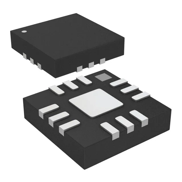
QPC4614TR13 is housed in a 20-pin, 4 × 4 mm QFN package with exposed thermal paddle (RF/DC GND). The package uses NiPdAu contact plating and complies with MSL Level 2 moisture sensitivity requirements.

Pin/Terminal Circuit Role Design Meaning
1, 15–20 Parallel Control Bits (C16, C8, C4, C2, C1, C0.5) Direct binary-weighted attenuation programming; LSB = C0.5 (0.5 dB), MSB = C16 (16 dB).
2, 14 RFIN / RFOUT 75Ω RF ports with no internal DC bias-can be externally DC-grounded for return-path or bidirectional applications.
3, 4, 5 DATA / CLK / LE Serial interface inputs; LE edge-triggered latch enables synchronous state updates and eliminates metastability in noisy environments.
6, 9 VDD +5 V supply pins-dual VDD inputs reduce supply inductance and improve PSRR across wideband RF operation.
10, 11, 18 GND Dedicated ground terminals-low-inductance connection points for RF and digital return paths to minimize coupling.
12 VSS −5 V negative supply input; grounding VSS enables internal NVG-removes need for external charge pump in space-constrained modules.
13 PBAR/S Mode select: logic low = parallel mode, logic high = serial mode-hardware-configurable interface selection without firmware change.

Key Features

Feature Design Value
Overshoot-free transient switching Patented circuit architecture ensures monotonic RF output during attenuation transitions-critical for minimizing MER degradation in live DOCSIS traffic.
DC-groundable RF ports RFIN and RFOUT have no internal DC voltage-allows direct connection to chassis ground or bias tees in optical node return-path amplifiers.
Three control interface modes Serial, latched parallel, and direct parallel modes support diverse system architectures-from microcontroller-based AGC to FPGA-driven tilt control-without external glue logic.
Internal negative voltage generator (NVG) Eliminates external −5 V supply when VSS is grounded-reduces BOM count and PCB area in MDU amplifier designs.
Power-up default attenuation Automatically initializes to 31.5 dB attenuation-prevents uncontrolled RF surge during cold start in headend and hub site equipment.

Applications

Optical Node Return Path MDU Amplifier Tilt Control

Use Scenario: Attenuating upstream signals (5–85 MHz) before optical transmission in hybrid fiber-coax (HFC) nodes to prevent overdrive of laser diodes.

IC Role / Device Role / Timing Role: Precision 75Ω RF attenuator placed between upstream amplifier stage and laser driver input; operates continuously under AGC feedback loop.

Use Value: Maintains constant upstream launch power despite varying subscriber activity-preserving MER > 38 dB and preventing laser clipping-induced distortion.

Use Scenario: Dynamically adjusting frequency-dependent gain slope across 5–1002 MHz in multi-dwelling unit (MDU) distribution amplifiers to compensate for cable loss tilt.

IC Role / Device Role / Timing Role: Digitally reconfigurable attenuation block inserted between amplifier stages; updated via FPGA-controlled parallel bus at sub-second intervals.

Use Value: Enables real-time tilt correction without mechanical potentiometers-reducing field maintenance and supporting remote calibration via SNMP.

Point-to-Point Microwave Link Pre-amplifier DOCSIS 4.0 Full Duplex Node AGC

Use Scenario: Protecting sensitive LNA inputs in licensed 2.5 GHz point-to-point backhaul links from strong adjacent-channel interferers.

IC Role / Device Role / Timing Role: Front-end programmable attenuator in receive chain; controlled via SPI interface synchronized to link timing reference.

Use Value: Provides 31.5 dB dynamic range with <1.2 dB insertion loss-maximizing SNR while preventing LNA saturation during burst interference events.

Use Scenario: Implementing fast-settling automatic gain control in full-duplex DOCSIS 4.0 nodes handling simultaneous 5–204 MHz upstream and 108–1218 MHz downstream spectra.

IC Role / Device Role / Timing Role: Core attenuation element in closed-loop AGC circuit; updated via serial interface with 150 ns switching speed to track rapid power fluctuations.

Use Value: Delivers stable composite power control across 200+ QAM channels-ensuring consistent upstream SNR and minimizing retransmission rates.

Equivalent & Alternatives

The following parts are listed as comparable options for similar digital step attenuator applications.

Alternative Part Technical Difference Application Difference Selection Advice
QPC4610TR13 Same 75Ω, 6-bit architecture but 0–15.5 dB range (0.5 dB steps); lower IIP3 (64 dBm @ 850 MHz); identical 4×4 mm QFN package and pinout. Targeted at mid-gain stages where full 31.5 dB range is unnecessary-e.g., fixed-attenuation inter-stage blocks in compact MDU amps. Select QPC4610TR13 when design requires lower cost and smaller dynamic range, with no change to PCB layout or firmware interface.
ADL5240ACPZ-R7 50Ω impedance; 31.5 dB range; 0.5 dB steps; higher insertion loss (2.0 dB @ 1 GHz); requires external negative supply; different 24-pin 4×4 mm LFCSP package. Designed for 50Ω test equipment and wireless infrastructure-not drop-in compatible with 75Ω CATV signal chains due to impedance mismatch and pinout divergence. Consider ADL5240ACPZ-R7 only for 50Ω lab-grade instrumentation or base station front-ends where 75Ω matching is not required.

Compared with QPC4614TR13, QPC4610TR13 offers identical form-factor and interface compatibility but reduced attenuation range and linearity-making it suitable for cost-sensitive, lower-dynamic-range CATV stages. ADL5240ACPZ-R7 provides comparable attenuation resolution but mandates 50Ω redesign and layout revision, limiting reuse in existing 75Ω HFC hardware.

Availability

QPC4614TR13 is available at Aetrix Electronics and suitable for optical node return-path conditioning, MDU amplifier tilt control, and DOCSIS 4.0 full-duplex AGC applications requiring stable component supply, long-term lifecycle assurance, and RoHS-compliant packaging.

Supply support for QPC4614TR13 includes scheduled delivery planning, volume procurement assistance, BOM continuity management, traceable sourcing, and lifecycle availability coordination for OEM customers, industrial embedded developers, connected-device designers, and electronics production programs.

Manufacturer

Qorvo is a U.S.-based semiconductor company specializing in RF solutions for infrastructure, defense, and mobile markets, with leadership in GaAs and GaN technologies for high-frequency, high-linearity applications.

The QPC4614TR13 belongs to Qorvo's broadband CATV attenuator product line, engineered specifically for 75Ω HFC network equipment-including optical nodes, amplifiers, and active splitters-where spectral purity, thermal stability, and fail-safe power-up behavior are critical.

FAQ

What is the recommended operating voltage for QPC4614TR13?

The QPC4614TR13 requires VDD = +2.7 V to +5.5 V (typical +5.0 V) and VSS = −5.5 V to −4.5 V (typical −5.0 V). These dual supplies enable its 75Ω RF ports to remain DC-groundable. Supply current is low: IDD = 200 µA and ISS = 100 µA in steady state. Operating outside these ranges risks permanent damage per absolute maximum ratings.

Does QPC4614TR13 support both serial and parallel control simultaneously?

No-QPC4614TR13 uses PBAR/S (Pin 13) to select mode: logic high enables serial control (DATA/CLK/LE), logic low enables parallel control (C16–C0.5). The device does not multiplex or time-share interfaces. Mode selection is static during operation and must be set before configuration; mixing control methods will result in undefined behavior.

Can QPC4614TR13 be used in 50Ω systems?

No-QPC4614TR13 is strictly a 75Ω device, optimized for impedance matching in CATV and HFC infrastructure. Using it in a 50Ω system causes significant return loss (>10 dB) and insertion loss degradation, compromising signal integrity. For 50Ω applications, Qorvo offers alternatives like the QPC4270, but QPC4614TR13 is not interoperable.

How does the internal negative voltage generator (NVG) work in QPC4614TR13?

When VSS (Pin 12) is grounded, QPC4614TR13 activates its internal NVG to generate −5 V for core RF switching elements. This eliminates the need for an external negative supply. To disable NVG and use an external −5 V source, remove the VSS-to-GND jumper and apply −5 V directly to Pin 12-verified in the evaluation board documentation and datasheet Section 10.

What is the power-up behavior of QPC4614TR13?

QPC4614TR13 defaults to maximum attenuation (31.5 dB) at power-on in both serial and parallel modes. This fail-safe state prevents RF overload during system initialization. To override this, apply the desired parallel control word (C16–C0.5) before power-up and hold LE low-details are specified in the Default Power-up State section (page 13) of the datasheet Rev D.

QPC4614TR13 Specifications

Product attributes
Attribute value
Manufacturer:
Qorvo
Package/Case:
20-VFQFN Exposed Pad
Series:
-
Packaging:
Tape & Reel (TR)
Product Status:
Active
Attenuation Value:
31.5dB
Frequency Range:
5 MHz ~ 2 GHz
Power (Watts):
-
Impedance:
75 Ohms
Grade:
-
Qualification:
-

QPC4614TR13 FAQ

1.How can I place an order for QPC4614TR13 through Aetrix?

Please submit a Request for Quotation (RFQ) for QPC4614TR13 on Aetrix. Our sales agent will provide a competitive quotation and guide you through the order confirmation once you accept the terms.

2.Are the price and stock information for QPC4614TR13 reliable?

The price and inventory of QPC4614TR13 are updated periodically and may fluctuate due to market conditions. Stock and pricing data are typically refreshed every 24 hours. Quotation validity for QPC4614TR13 is usually 5 days.

3.What payment methods are accepted for QPC4614TR13?

We accept Wire Transfer, PayPal, Credit Card, Western Union, MoneyGram, and Escrow for QPC4614TR13 transactions.

Note: Certain payment methods may incur a processing fee.

4.How is shipping managed for QPC4614TR13?

QPC4614TR13 orders can be shipped via leading logistics carriers, including DHL, UPS, FedEx, TNT, or Registered Mail.

Once your QPC4614TR13 order is processed, you will receive an email with the shipment details and tracking number.

Note: Tracking information may take up to 24 hours to appear. Express delivery typically takes 3–5 business days.

5.How can I obtain technical support or documentation for QPC4614TR13?

For technical support, including QPC4614TR13 datasheets, pinout diagrams, or application guidance, please contact our engineering support team. They can provide detailed documentation and assistance for your QPC4614TR13 requirements.

6.How does Aetrix verify that QPC4614TR13 is sourced from the original manufacturer or authorized distributors?

All QPC4614TR13 products on Aetrix are procured from qualified distributors and authorized channels. Our dedicated quality assurance team conducts strict verification, including traceability checks and, if necessary, third-party testing. This ensures that QPC4614TR13 meets industry standards.

7.What is the process for return or replacement of QPC4614TR13?

All QPC4614TR13 units undergo pre-shipment inspection (PSI). If there is an issue with QPC4614TR13, returns or replacements are accepted under the following conditions:

1.Quantity discrepancies, incorrect items, or visible external defects (such as breakage or corrosion), acknowledged by Aetrix.

2.The issue is reported within 90 days of delivery.

3.The QPC4614TR13 part is unused and in its original packaging.

Return procedure for QPC4614TR13:

1.Submit a request within 90 days.

2.Obtain a Return Material Authorization (RMA) from Aetrix.

QPC4614TR13 Tags

  • QPC4614TR13
  • QPC4614TR13 PDF
  • QPC4614TR13 Datasheet
  • QPC4614TR13 Specifications
  • QPC4614TR13 Images
  • Qorvo
  • Qorvo QPC4614TR13
  • Buy QPC4614TR13
  • QPC4614TR13 Price
  • QPC4614TR13 Distributor
  • QPC4614TR13 Supplier
  • QPC4614TR13 Wholesale
Related Products
PAT0510S-C-3DB-T10
PAT0510S-C-3DB-T10

Susumu

PAT0510S-C-10DB-T10
PAT0510S-C-10DB-T10

Susumu

PAT0510S-C-2DB-T10
PAT0510S-C-2DB-T10

Susumu

PAT1220-C-10DB-T5
PAT1220-C-10DB-T5

Susumu

PAT1220-C-6DB-T5
PAT1220-C-6DB-T5

Susumu

PAT1220-C-0DB-T5
PAT1220-C-0DB-T5

Susumu

PAT1220-C-3DB-T5
PAT1220-C-3DB-T5

Susumu

PAT1220-C-5DB-T5
PAT1220-C-5DB-T5

Susumu

PAT1220-C-8DB-T5
PAT1220-C-8DB-T5

Susumu

MAADSS0008TR-3000
MAADSS0008TR-3000

MACOM Technology Solutions

MAATSS0018TR-3000
MAATSS0018TR-3000

MACOM Technology Solutions
PE43205B-Z
PE43205B-Z

pSemi

Tech Hub

Search

Search

PRODUCT

PRODUCT

PHONE

PHONE

USER

USER