Send an Inquiry

To receive a quote for your project, please fill in the following information, and we’ll get back to you promptly.

Name*
Company*
Email Address*
Phone/WhatsApp
Part Number*
Quantity*
Message
Submit Inventory List

Please fill in the following information, and we’ll get back to you promptly.

Name*
Company*
Email Address*
Phone/WhatsApp
Upload My List
Message

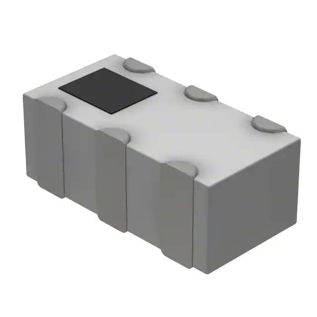
Qorvo RFXF0010-TR13

Part No.:
RFXF0010-TR13
Manufacturer:
Qorvo
Category:
Balun
Package:
4-SMD, No Lead
Datasheet:
AetrixRFXF0010-TR13.pdf
Description:
45 TO 1200MHZ 1:1 TRANSFORMER
Quantity:
Payment:
Payment
Shipping:
Shipping

Inventory:3,081

Please send an inquiry. Send us your inquiry, and we will respond immediately.

Part Number
Quantity*
Price
Name*
Company
Email*
Comments

Product details

Overview

RFXF0010-TR13 from RF Micro Devices is a 1:1 surface-mount RF transformer designed for unbalanced-to-balanced signal conversion in broadband RF systems, operating from 45 MHz to 1200 MHz with 75 Ω characteristic impedance, ≤1.3 dB insertion loss (typ.), and 180° nominal phase difference between secondary outputs.

For engineers reviewing the RFXF0010-TR13 datasheet, pinout, applications, or equivalent options, key selection criteria include amplitude/phase balance across 45–1200 MHz, RoHS-compliant SP5 package compatibility, and 75 Ω impedance matching for CATV and wireless front-end designs.

Technical Context

The RFXF0010-TR13 implements a transmission-line-based 1:1 turns ratio transformer with tertiary balance winding architecture, enabling precise 180° differential output generation. It supports unbalanced input (Port 1) to balanced differential output (Ports 2 & 3), with ground-referenced primary return path.

Designed for fixed-frequency broadband operation-not tunable or active-it delivers stable amplitude balance (≤0.5 dB typ. up to 600 MHz) and phase balance (≤6.0° max across full band), meeting requirements for impedance transformation and common-mode rejection in RF signal paths.

Key Specifications

ParameterValue and Actual Design Meaning
Frequency Range45 MHz to 1200 MHz - supports full-band CATV, ISM, and wireless infrastructure signal conditioning
Impedance Ratio1:1 - preserves 75 Ω system impedance without scaling, simplifying PCB layout and matching network design
Insertion Loss0.8–1.3 dB (typ.) - ensures minimal signal attenuation across three frequency bands, critical for low-noise receiver front ends
Amplitude Balance0.2–1.1 dB (max) - maintains consistent signal level between differential outputs, reducing distortion in IQ demodulators
Phase Balance0.8–6.0° (max) - sustains tight 180° differential timing alignment, essential for image rejection and mixer LO integrity
RF Power Rating2 W - enables use in medium-power transmit/receive paths without thermal derating in standard FR4 layouts
Operating Temp−40°C to +100°C - supports deployment in outdoor broadband equipment and industrial wireless gateways

Pinout & Package

Package: SP5 - industry-standard 4-pin surface-mount footprint (0.120" × 0.120", 3.05 mm × 3.05 mm), lead-free and RoHS compliant.

Pin/TerminalCircuit RoleDesign Meaning
1PRIMARY DOTUnbalanced RF input (Port 1); dot-marked end defines phase reference for 180° output polarity
2PRIMARYPrimary winding return / ground connection; provides RF return path for input side
3SECONDARY DOTBalanced output (Port 3); dot-marked terminal carries inverted phase relative to Port 2
4SECONDARYBalanced output (Port 2); non-dot terminal forms differential pair with Pin 3 for 180° output

Key Features

FeatureDesign Value
Tertiary balance windingEnables precise 180° phase split and improved common-mode rejection over wide bandwidth
75 Ω characteristic impedanceDirect interface with CATV coaxial infrastructure and 75 Ω RF test equipment without external matching
RoHS-compliant SP5 packageMeets environmental compliance mandates and supports automated SMT assembly with standard reflow profiles
Low insertion loss (≤1.3 dB)Preserves signal-to-noise ratio in cascaded RF stages, especially critical in LNA and mixer interfaces
Amplitude/phase balance specsGuarantees <1.1 dB / <6.0° mismatch across full 45–1200 MHz range for reliable IQ signal integrity

Applications

CATV Distribution AmplifiersISM Band Transceivers

Use Scenario: Signal splitting and impedance-matched distribution in headend and node amplifiers feeding multiple downstream coaxial drops.

IC Role / Device Role / Timing Role: Unbalanced-to-balanced transformer providing 75 Ω interface and 180° phase inversion for push-pull amplifier drive.

Use Value: Maintains amplitude/phase balance ≤0.5 dB/≤6.0° across 54–1002 MHz CATV band, minimizing intermodulation distortion in multi-carrier systems.

Use Scenario: LO injection and IF coupling in 900 MHz and 2.4 GHz ISM transceivers using direct-conversion architectures.

IC Role / Device Role / Timing Role: Passive 1:1 balun converting single-ended LO to differential input for quadrature mixers.

Use Value: Delivers ≤1.1 dB insertion loss and ≤0.4 dB amplitude balance at 915 MHz, preserving LO purity and mixer linearity.

Wireless Infrastructure MonitoringRF Test & Calibration Equipment

Use Scenario: Bidirectional signal sampling in remote radio unit (RRU) monitoring paths requiring high isolation and broadband fidelity.

IC Role / Device Role / Timing Role: Balanced tap coupler supporting simultaneous forward/reflected power measurement with common-mode noise rejection.

Use Value: Achieves >14 dB input return loss up to 600 MHz, ensuring minimal VSWR impact on main signal path during sampling.

Use Scenario: Impedance-matched signal routing between 75 Ω test instruments (spectrum analyzers, VNAs) and 50 Ω DUTs via adapter networks.

IC Role / Device Role / Timing Role: Fixed-ratio passive balun enabling accurate 75 Ω ↔ 50 Ω differential interface calibration.

Use Value: Provides verified 75 Ω port impedance and <1.3 dB loss across 45–1200 MHz, supporting traceable lab-grade measurements.

Equivalent & Alternatives

The following parts are listed as comparable options for similar RF transformer applications.

Alternative PartTechnical DifferenceApplication DifferenceSelection Advice
Mini-Circuits TC1-1-75+Same 1:1 ratio and 75 Ω impedance, but wider 0.1–500 MHz bandwidth; higher insertion loss (1.8 dB typ. at 100 MHz)Preferred for sub-500 MHz legacy CATV; not rated for >600 MHz operation like RFXF0010-TR13Select when lower-cost evaluation or narrowband 5–500 MHz use is prioritized over 600–1200 MHz coverage
TDK HHM1595A1Integrated 75 Ω balun with embedded ESD protection; narrower 50–1000 MHz range; 1.5 dB max insertion lossSuitable for portable wireless receivers where ESD robustness is mandatory; lacks RFXF0010-TR13's 1200 MHz upper limitChoose when board-level ESD immunity is required and 1000–1200 MHz operation is non-critical

Compared with TC1-1-75+ and HHM1595A1, the RFXF0010-TR13 uniquely extends usable bandwidth to 1200 MHz while maintaining ≤1.3 dB loss and <6.0° phase error-making it optimal for next-gen broadband infrastructure where full UHF coverage and tight balance are design-critical.

Availability

RFXF0010-TR13 is available at Aetrix Electronics and suitable for CATV distribution amplifiers, ISM band transceivers, wireless infrastructure monitoring, and RF test equipment requiring stable component supply and guaranteed RoHS compliance.

Supply support for RFXF0010-TR13 includes scheduled delivery planning, volume procurement assistance, BOM continuity management, traceable sourcing, and lifecycle availability coordination for OEM customers, industrial embedded developers, connected-device designers, and electronics production programs.

Manufacturer

RF Micro Devices (now part of Qorvo) was a U.S.-based fabless semiconductor company specializing in high-performance RF solutions for wireless communications, founded in 1991 and headquartered in Greensboro, NC.

The RFXF0010-TR13 belongs to RFMD's passive RF component portfolio, engineered specifically for broadband unbalanced-to-balanced signal conversion in cost-sensitive, high-volume CATV and wireless infrastructure applications.

FAQ

What is the exact impedance specification of the RFXF0010-TR13?

The RFXF0010-TR13 has a 75 Ω characteristic impedance, confirmed in its datasheet under "Nominal Operating Parameters" and validated by S-parameter measurements. This matches standard CATV and broadcast RF systems, eliminating need for external impedance-matching components when interfacing with 75 Ω sources or loads. The RFXF0010-TR13 maintains this impedance across its full 45–1200 MHz operating range.

Does the RFXF0010-TR13 support differential signaling above 1 GHz?

Yes-the RFXF0010-TR13 is specified for operation up to 1200 MHz, with measured amplitude balance ≤1.1 dB and phase balance ≤6.0° at 1000 MHz. Its performance remains within datasheet limits through the entire band, including UHF TV channels and LTE Band 7/13 uplink frequencies. The RFXF0010-TR13 is routinely used in 1.1 GHz wireless infrastructure monitoring paths.

Is the RFXF0010-TR13 pin-compatible with other SP5-packaged RF transformers?

No documented pin-to-pin compatibility exists between the RFXF0010-TR13 and other SP5 transformers. Its pin assignment-PRIMARY DOT (1), PRIMARY (2), SECONDARY DOT (3), SECONDARY (4)-is specific to its 180° balun function and differs from generic 1:1 transformers that may assign pins for center-tapped or autotransformer configurations. Always verify pinout against schematic before substitution.

What is the maximum RF power handling capability of the RFXF0010-TR13?

The RFXF0010-TR13 has an absolute maximum RF power rating of 2 W, as stated in the "Absolute Maximum Ratings" table. This applies across its full temperature range (−40°C to +100°C). Exceeding 2 W risks permanent damage. The RFXF0010-TR13 is commonly deployed in 1 W-class CATV line drivers and ISM transceiver PA output stages without derating.

How does the RFXF0010-TR13 achieve phase balance below 6° across 1200 MHz?

The RFXF0010-TR13 achieves tight phase balance via a precision-wound transmission-line structure with tertiary balance winding, optimized during core fabrication and winding tension control. Measured phase deviation stays ≤6.0° across all frequency bands (45–100, 100–600, 600–1200 MHz), with typical values as low as 0.8° at 100 MHz. This architecture is intrinsic to the RFXF0010-TR13 design and not adjustable post-manufacture.

RFXF0010-TR13 Specifications

Product attributes
Attribute value
Manufacturer:
Qorvo
Series:
-
Package/Case:
4-SMD, No Lead
Packaging:
Tape & Reel (TR)
Product Status:
Active
Frequency Range:
45MHz ~ 1.2GHz
Impedance - Unbalanced/Balanced:
1:1
Phase Difference:
180°
Insertion Loss (Max):
1.3dB
Return Loss (Min):
13dB
Mounting Type:
Surface Mount

RFXF0010-TR13 FAQ

1.How can I place an order for RFXF0010-TR13 through Aetrix?

Please submit a Request for Quotation (RFQ) for RFXF0010-TR13 on Aetrix. Our sales agent will provide a competitive quotation and guide you through the order confirmation once you accept the terms.

2.Are the price and stock information for RFXF0010-TR13 reliable?

The price and inventory of RFXF0010-TR13 are updated periodically and may fluctuate due to market conditions. Stock and pricing data are typically refreshed every 24 hours. Quotation validity for RFXF0010-TR13 is usually 5 days.

3.What payment methods are accepted for RFXF0010-TR13?

We accept Wire Transfer, PayPal, Credit Card, Western Union, MoneyGram, and Escrow for RFXF0010-TR13 transactions.

Note: Certain payment methods may incur a processing fee.

4.How is shipping managed for RFXF0010-TR13?

RFXF0010-TR13 orders can be shipped via leading logistics carriers, including DHL, UPS, FedEx, TNT, or Registered Mail.

Once your RFXF0010-TR13 order is processed, you will receive an email with the shipment details and tracking number.

Note: Tracking information may take up to 24 hours to appear. Express delivery typically takes 3–5 business days.

5.How can I obtain technical support or documentation for RFXF0010-TR13?

For technical support, including RFXF0010-TR13 datasheets, pinout diagrams, or application guidance, please contact our engineering support team. They can provide detailed documentation and assistance for your RFXF0010-TR13 requirements.

6.How does Aetrix verify that RFXF0010-TR13 is sourced from the original manufacturer or authorized distributors?

All RFXF0010-TR13 products on Aetrix are procured from qualified distributors and authorized channels. Our dedicated quality assurance team conducts strict verification, including traceability checks and, if necessary, third-party testing. This ensures that RFXF0010-TR13 meets industry standards.

7.What is the process for return or replacement of RFXF0010-TR13?

All RFXF0010-TR13 units undergo pre-shipment inspection (PSI). If there is an issue with RFXF0010-TR13, returns or replacements are accepted under the following conditions:

1.Quantity discrepancies, incorrect items, or visible external defects (such as breakage or corrosion), acknowledged by Aetrix.

2.The issue is reported within 90 days of delivery.

3.The RFXF0010-TR13 part is unused and in its original packaging.

Return procedure for RFXF0010-TR13:

1.Submit a request within 90 days.

2.Obtain a Return Material Authorization (RMA) from Aetrix.

RFXF0010-TR13 Tags

  • RFXF0010-TR13
  • RFXF0010-TR13 PDF
  • RFXF0010-TR13 Datasheet
  • RFXF0010-TR13 Specifications
  • RFXF0010-TR13 Images
  • Qorvo
  • Qorvo RFXF0010-TR13
  • Buy RFXF0010-TR13
  • RFXF0010-TR13 Price
  • RFXF0010-TR13 Distributor
  • RFXF0010-TR13 Supplier
  • RFXF0010-TR13 Wholesale
Related Products
2450BL15B0100001E
2450BL15B0100001E

Johanson Technology Inc.

0900BL15D0050001E
0900BL15D0050001E

Johanson Technology Inc.

0900PC16J0042001E
0900PC16J0042001E

Johanson Technology Inc.

2450BM15A0002001E
2450BM15A0002001E

Johanson Technology Inc.

2450BM14G0011001T
2450BM14G0011001T

Johanson Technology Inc.

BD0810N50100AHF
BD0810N50100AHF

TTM Technologies, Inc.

1720BL15B0050001E
1720BL15B0050001E

Johanson Technology Inc.

0900PC15A0036001E
0900PC15A0036001E

Johanson Technology Inc.

0868BM15C0001001E
0868BM15C0001001E

Johanson Technology Inc.

0915BM15A0001001E
0915BM15A0001001E

Johanson Technology Inc.
HHM1776B3
HHM1776B3

TDK Corporation

2450BM14E0003001T
2450BM14E0003001T

Johanson Technology Inc.

Tech Hub

Search

Search

PRODUCT

PRODUCT

PHONE

PHONE

USER

USER











