Send an Inquiry

To receive a quote for your project, please fill in the following information, and we’ll get back to you promptly.

Name*
Company*
Email Address*
Phone/WhatsApp
Part Number*
Quantity*
Message
Submit Inventory List

Please fill in the following information, and we’ll get back to you promptly.

Name*
Company*
Email Address*
Phone/WhatsApp
Upload My List
Message

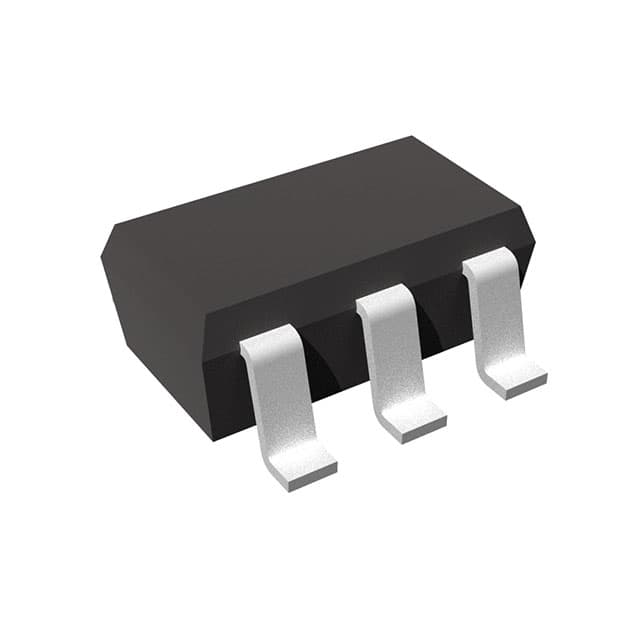
Nexperia USA Inc. RP114N281D5-TR-FE

Part No.:
RP114N281D5-TR-FE
Manufacturer:
Nexperia USA Inc.
Category:
Voltage Regulators - Linear, Low Drop Out (LDO) Regulators
Package:
SC-74A, SOT-753
Datasheet:
AetrixRP114N281D5-TR-FE.pdf
Description:
RP114N - Low Voltage 300mA LDO R
Quantity:
Payment:
Payment
Shipping:
Shipping

Inventory:3,000

Please send an inquiry. Send us your inquiry, and we will respond immediately.

Part Number
Quantity*
Price
Name*
Company
Email*
Comments

Product details

Overview

RP114N281D5-TR-FE from Ricoh Electronics is a 300 mA, 2.85 V fixed-output CMOS LDO regulator in SOT-23-5 package with ±1.0% output accuracy (VSET > 2.0 V), 0.25 V typical dropout at 300 mA, and 75 dB ripple rejection at 1 kHz. It features H-active chip enable, auto-discharge function, 50 µA supply current, and operates from 1.4 V to 5.25 V input - ideal for battery-powered portable communication equipment requiring stable low-noise bias.

For engineers reviewing the RP114N281D5-TR-FE datasheet, RP114N281D5-TR-FE pinout, RP114N281D5-TR-FE application, or RP114N281D5-TR-FE equivalent, key selection criteria include its auto-discharge capability during standby, thermal performance in SOT-23-5 (660 mW PD), ±80 ppm/°C temperature drift, and compatibility with 1.0 µF ceramic output capacitors.

Technical Context

The RP114N281D5-TR-FE integrates a precision voltage reference, error amplifier, and low-RON N-channel pass transistor to achieve low dropout and high PSRR. Its internal feedback network fixes VOUT at 2.85 V with no external resistors required.

The "D" suffix denotes active-H CE with integrated auto-discharge circuitry that rapidly discharges the output capacitor when CE transitions to low, preventing residual voltage hold-up in power-gated subsystems - a critical feature for fast wake/sleep sequencing in handheld devices.

Key Specifications

Parameter Value and Actual Design Meaning
Output Voltage 2.85 V (fixed, ±1.0% accuracy at 25°C, ±3.0% over −40°C to +85°C)
Max Output Current 300 mA (supports compact DC-DC post-regulation in space-constrained designs)
Dropout Voltage 0.25 V typ. at 300 mA (enables operation down to 3.1 V input for 2.85 V rail)
Ripple Rejection 75 dB at 1 kHz (suppresses switching noise from upstream converters)
Supply Current 50 µA typ. (extends battery life in always-on sensor nodes)
Standby Current 0.1 µA typ. (minimizes quiescent drain during system sleep)
Operating Input Range 1.4 V to 5.25 V (compatible with single-cell Li-ion, LiFePO4, and 3.3 V/5 V rails)

Pinout & Package

SOT-23-5 package (JEDEC MO-178AA) with exposed pad thermally connected to GND; recommended PCB layout includes direct thermal via connection to inner ground plane for reliable 300 mA operation.

Pin/Terminal Circuit Role Design Meaning
1 VDD Main input power pin; requires 1.0 µF ceramic decoupling capacitor placed ≤2 mm from pin
2 GND Analog/digital ground reference; connects to thermal pad and system ground plane
3 CE Chip enable input (H-active); internal pull-down ensures default disable on power-up
4 NC No internal connection; must be left floating or tied to GND (not VDD)
5 VOUT Regulated 2.85 V output; requires ≥1.0 µF ceramic capacitor with ESR < 100 mΩ

Key Features

Feature Design Value
Auto-discharge function Actively pulls VOUT to 0 V within 1 ms after CE deactivation - eliminates need for external discharge FET in portable systems
Ceramic capacitor compatibility Stable with ≥1.0 µF X5R/X7R ceramics (no ESR requirement), reducing BOM count vs. tantalum-based LDOs
Low temperature drift ±80 ppm/°C output variation ensures stable reference for ADCs and RF front-ends across industrial temperature range
High PSRR at low frequency 75 dB at 1 kHz enables clean power delivery to noise-sensitive analog circuits powered from noisy SMPS outputs
Ultra-low standby current 0.1 µA max allows multi-year battery life in IoT endpoint applications with infrequent wake cycles

Applications

Smartphone Baseband Power Wireless Headset Audio Codec

Use Scenario: Supplies clean 2.85 V bias to LTE/WCDMA baseband processor core logic during active transmission.

IC Role / Device Role / Timing Role: Primary low-noise post-regulator for RF transceiver digital core, synchronized to modem sleep/wake signals via CE pin.

Use Value: 75 dB PSRR suppresses switching noise from PMIC buck converters, preventing EVM degradation in 4G/5G transmission.

Use Scenario: Powers stereo audio DAC and class-D headphone driver in Bluetooth earbuds with dynamic load current (1–300 mA).

IC Role / Device Role / Timing Role: Low-dropout bias source with auto-discharge, enabling rapid power cycling between audio playback and deep-sleep modes.

Use Value: 0.1 µA standby current extends 200 mAh battery life to >120 hours of mixed-use runtime per charge cycle.

Digital Still Camera Sensor Bias Industrial Handheld Scanner MCU

Use Scenario: Provides regulated 2.85 V to CMOS image sensor analog front-end during exposure capture.

IC Role / Device Role / Timing Role: Precision voltage source with ±1.0% accuracy and ±80 ppm/°C drift, referenced to camera's internal temperature sensor.

Use Value: Stable output minimizes fixed-pattern noise (FPN) and dark current variation across −20°C to +60°C operating range.

Use Scenario: Powers ARM Cortex-M4 microcontroller and 2.4 GHz BLE radio in ruggedized barcode scanner used in warehouse logistics.

IC Role / Device Role / Timing Role: Main system LDO with CE-controlled sequencing, coordinating with battery fuel gauge and motor driver enable signals.

Use Value: 0.25 V dropout allows full 300 mA operation even as single-cell Li-ion voltage drops to 3.1 V, extending usable battery capacity by 18%.

Equivalent & Alternatives

The following parts are listed as comparable options for similar LDO regulator applications.

Alternative Part Technical Difference Application Difference Selection Advice
TPS7A0528PDBVR 200 mA output, 2.8 V fixed, no auto-discharge, 25 µA IQ Lacks auto-discharge; requires external circuit for rapid VOUT discharge Select if lower IQ is prioritized over discharge speed and higher current capability is not needed
MCP1700T-2802E/TT 250 mA output, 2.8 V fixed, no CE pin, 1.9 µA IQ Always-on operation only; no enable control or auto-discharge Select for ultra-low-power always-on sensors where CE sequencing is unnecessary

Compared with TPS7A0528PDBVR and MCP1700T-2802E/TT, RP114N281D5-TR-FE uniquely combines 300 mA drive, auto-discharge, and H-active CE in SOT-23-5 - making it optimal for portable systems requiring fast, controlled power gating without added discrete components.

Availability

RP114N281D5-TR-FE is available at Aetrix Electronics and suitable for smartphone baseband power, wireless headset audio codecs, digital still camera sensor bias, and industrial handheld scanner MCU applications requiring stable component supply with guaranteed long-term sourcing.

Supply support for RP114N281D5-TR-FE includes scheduled delivery planning, volume procurement assistance, BOM continuity management, traceable sourcing, and lifecycle availability coordination for OEM customers, industrial embedded developers, connected-device designers, and electronics production programs.

Manufacturer

Ricoh Electronics, Inc. is a Japanese semiconductor manufacturer specializing in power management ICs, voltage regulators, and battery management solutions for portable and industrial electronics.

The RP114x series is designed for high-efficiency, low-noise power regulation in battery-powered portable equipment - emphasizing ultra-low IQ, fast transient response, and integrated functional safety features like auto-discharge.

FAQ

What is the minimum input voltage required for stable 2.85 V output at 300 mA?

The RP114N281D5-TR-FE requires a minimum input voltage of 3.10 V to maintain 2.85 V output at 300 mA load, based on its typical 0.25 V dropout voltage at that condition. At light loads (<1 mA), operation is stable down to 1.4 V input, but full-rated current requires VIN ≥ VOUT + VDIF.

Does this device require an external resistor network to set the output voltage?

No. RP114N281D5-TR-FE has an internally trimmed 2.85 V output; no external resistors are needed. The "281D5" in the part number explicitly denotes 2.85 V fixed output with auto-discharge (D) and 0.01 V resolution (5), per Ricoh's naming convention.

Can the NC pin (Pin 4) be connected to GND or VDD for improved thermal or electrical performance?

No. Pin 4 is unconnected internally and must remain floating or be tied to GND only - never to VDD. Connecting it to VDD may cause latch-up or parametric shift. Thermal performance is managed solely through the exposed pad (Pin 2), which must be soldered to a GND copper area with ≥4 thermal vias.

How does the auto-discharge function behave under varying load conditions?

Auto-discharge activates only when CE transitions from high to low and is independent of load current. It discharges VOUT to <0.1 V within 1 ms regardless of output capacitance (≤10 µF) or load state, verified per Figure 22 in the EA-236-240517 datasheet - ensuring deterministic power-down behavior across all operating conditions.

RP114N281D5-TR-FE Specifications

Product attributes
Attribute value
Manufacturer:
Nexperia USA Inc.
Series:
RP114x
Package/Case:
SC-74A, SOT-753
Packaging:
Bulk
Product Status:
Active
Output Configuration:
Positive
Output Type:
Fixed
Number of Regulators:
1
Voltage - Input (Max):
5.25V
Voltage - Output (Min/Fixed):
2.85V
Voltage - Output (Max):
-
Voltage Dropout (Max):
0.3V @ 300mA
Current - Output:
300mA
Current - Quiescent (Iq):
75 µA
Current - Supply (Max):
-
PSRR:
75dB (1kHz)
Control Features:
Enable
Protection Features:
Over Current
Operating Temperature:
-40°C ~ 85°C (TA)
Grade:
-
Qualification:
-
Mounting Type:
Surface Mount
Supplier Device Package:
SOT-23-5

RP114N281D5-TR-FE FAQ

1.How can I place an order for RP114N281D5-TR-FE through Aetrix?

Please submit a Request for Quotation (RFQ) for RP114N281D5-TR-FE on Aetrix. Our sales agent will provide a competitive quotation and guide you through the order confirmation once you accept the terms.

2.Are the price and stock information for RP114N281D5-TR-FE reliable?

The price and inventory of RP114N281D5-TR-FE are updated periodically and may fluctuate due to market conditions. Stock and pricing data are typically refreshed every 24 hours. Quotation validity for RP114N281D5-TR-FE is usually 5 days.

3.What payment methods are accepted for RP114N281D5-TR-FE?

We accept Wire Transfer, PayPal, Credit Card, Western Union, MoneyGram, and Escrow for RP114N281D5-TR-FE transactions.

Note: Certain payment methods may incur a processing fee.

4.How is shipping managed for RP114N281D5-TR-FE?

RP114N281D5-TR-FE orders can be shipped via leading logistics carriers, including DHL, UPS, FedEx, TNT, or Registered Mail.

Once your RP114N281D5-TR-FE order is processed, you will receive an email with the shipment details and tracking number.

Note: Tracking information may take up to 24 hours to appear. Express delivery typically takes 3–5 business days.

5.How can I obtain technical support or documentation for RP114N281D5-TR-FE?

For technical support, including RP114N281D5-TR-FE datasheets, pinout diagrams, or application guidance, please contact our engineering support team. They can provide detailed documentation and assistance for your RP114N281D5-TR-FE requirements.

6.How does Aetrix verify that RP114N281D5-TR-FE is sourced from the original manufacturer or authorized distributors?

All RP114N281D5-TR-FE products on Aetrix are procured from qualified distributors and authorized channels. Our dedicated quality assurance team conducts strict verification, including traceability checks and, if necessary, third-party testing. This ensures that RP114N281D5-TR-FE meets industry standards.

7.What is the process for return or replacement of RP114N281D5-TR-FE?

All RP114N281D5-TR-FE units undergo pre-shipment inspection (PSI). If there is an issue with RP114N281D5-TR-FE, returns or replacements are accepted under the following conditions:

1.Quantity discrepancies, incorrect items, or visible external defects (such as breakage or corrosion), acknowledged by Aetrix.

2.The issue is reported within 90 days of delivery.

3.The RP114N281D5-TR-FE part is unused and in its original packaging.

Return procedure for RP114N281D5-TR-FE:

1.Submit a request within 90 days.

2.Obtain a Return Material Authorization (RMA) from Aetrix.

RP114N281D5-TR-FE Tags

  • RP114N281D5-TR-FE
  • RP114N281D5-TR-FE PDF
  • RP114N281D5-TR-FE Datasheet
  • RP114N281D5-TR-FE Specifications
  • RP114N281D5-TR-FE Images
  • Nexperia USA Inc.
  • Nexperia USA Inc. RP114N281D5-TR-FE
  • Buy RP114N281D5-TR-FE
  • RP114N281D5-TR-FE Price
  • RP114N281D5-TR-FE Distributor
  • RP114N281D5-TR-FE Supplier
  • RP114N281D5-TR-FE Wholesale
Related Products
MIC5504-1.8YM5-TR
MIC5504-1.8YM5-TR

Microchip Technology

MIC5504-3.3YM5-TR
MIC5504-3.3YM5-TR

Microchip Technology

MIC5365-3.0YC5-TR
MIC5365-3.0YC5-TR

Microchip Technology

MIC5365-1.8YC5-TR
MIC5365-1.8YC5-TR

Microchip Technology

MIC5365-2.5YC5-TR
MIC5365-2.5YC5-TR

Microchip Technology

MIC5365-3.3YC5-TR
MIC5365-3.3YC5-TR

Microchip Technology

MIC5365-3.3YD5-TR
MIC5365-3.3YD5-TR

Microchip Technology

MIC5317-3.3YM5-TR
MIC5317-3.3YM5-TR

Microchip Technology

TLV1117LV33DCYR
TLV1117LV33DCYR

Texas Instruments

MIC5317-3.3YMT-TZ
MIC5317-3.3YMT-TZ

Microchip Technology

MIC5528-3.3YMT-TR
MIC5528-3.3YMT-TR

Microchip Technology

TLV75801PDRVR
TLV75801PDRVR

Texas Instruments

Tech Hub

Search

Search

PRODUCT

PRODUCT

PHONE

PHONE

USER

USER