Send an Inquiry

To receive a quote for your project, please fill in the following information, and we’ll get back to you promptly.

Name*
Company*
Email Address*
Phone/WhatsApp
Part Number*
Quantity*
Message
Submit Inventory List

Please fill in the following information, and we’ll get back to you promptly.

Name*
Company*
Email Address*
Phone/WhatsApp
Upload My List
Message

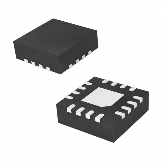
Semtech Corporation SC2604ULTRT

Part No.:
SC2604ULTRT
Manufacturer:
Semtech Corporation
Category:
DC DC Switching Controllers
Package:
8-UFDFN Exposed Pad
Datasheet:
AetrixSC2604ULTRT.pdf
Description:
IC REG CTRLR BOOST SMD
Quantity:
Payment:
Payment
Shipping:
Shipping

Inventory:2,917

Please send an inquiry. Send us your inquiry, and we will respond immediately.

Part Number
Quantity*
Price
Name*
Company
Email*
Comments

Product details

Overview

SC2604ULTRT from Semtech is a voltage-mode PWM boost controller with input disconnect FET drive, designed for 4.5V–16V input DC/DC conversion. It delivers up to 95% efficiency at 400kHz switching frequency, features 1% reference accuracy, programmable soft start, and hiccup-mode over-current protection. It serves in auxiliary supplies and high-density portable power rails.

For engineers reviewing the SC2604ULTRT datasheet, pinout, applications, or equivalent options, key selection criteria include its MLPD-UT8 package thermal performance (50°C/W), 800mA gate drive capability, input disconnect control via DRV pin, and integrated compensation eliminating external loop components.

Technical Context

The SC2604ULTRT implements a fixed-frequency voltage-mode control architecture with internal ramp generation and an error amplifier referenced to a 1.25V ±1% bandgap. Its PWM comparator compares the error amplifier output against a 400kHz sawtooth ramp to generate duty-cycle-modulated gate signals.

It integrates dual gate drivers: GATE drives the main boost switch (N-channel MOSFET) with 0.8A source/sink capability, while DRV drives an external N-channel input disconnect FET using a charge-pump floating driver. Hiccup-mode OCP is triggered by CS pin voltage exceeding 72mV, initiating automatic retry via OCP/EN capacitor discharge/charge cycling.

Key Specifications

ParameterValue and Actual Design Meaning
Switching Frequency400 kHz typical; enables compact magnetics and predictable EMI filtering design.
Input Voltage Range4.5 V to 16 V; supports wide-range industrial and consumer input rails including 5V, 12V, and 15V systems.
Reference Accuracy±1% at 1.25 V; ensures tight output voltage regulation across temperature and load without trimming.
GATE Drive Strength0.8 A source/sink; directly drives medium-power N-MOSFETs (e.g., AO4412) without external buffers.
DRV Drive Capability45 µA sink/source; sufficient to drive low-threshold N-FETs (e.g., IRF7821) for input disconnect function.
Current Limit Threshold72 mV typical (VIN–CS); sets peak inductor current with minimal sensing resistor loss (e.g., 10 mΩ yields 7.2 A).
Soft Start Charge Current55 µA; controls ramp rate of SS/VREF pin to limit in-rush current and prevent output overshoot.
Shutdown Current<200 µA; enables ultra-low quiescent power in battery-backed or standby systems.

Pinout & Package

SC2604ULTRT is packaged in a 2 mm × 3 mm × 0.6 mm MLPD-UT8 thermally enhanced lead-free, halogen-free RoHS-compliant package with exposed thermal pad connected to ground.

Pin/TerminalCircuit RoleDesign Meaning
1 - CSCurrent sense input (negative)Senses voltage drop across input-side current-sense resistor; triggers OCP when VIN–CS exceeds 72 mV.
2 - VINDevice supply voltagePowers internal circuitry and serves as positive current sense node; UVLO activates at 4.2 V rising.
3 - GATEPWM gate driver outputDrives boost switch FET gate with rail-to-rail swing (0 V to VIN); rated for 0.8 A peak current.
4 - GNDGround referencePrimary return path for analog and power circuits; must be tied to thermal pad via multiple vias.
5 - SS/VREFSoft-start timing & reference voltageProvides 1.25 V reference and accepts soft-start capacitor; pulled low during shutdown to disable PWM.
6 - FBError amplifier inverting inputCompares feedback voltage from output divider against 1.25 V reference to regulate output voltage.
7 - OCP/ENHiccup timer & enable controlCapacitor sets hiccup off-time; pulling below 590 mV disables both disconnect and PWM functions.
8 - DRVDisconnect FET gate driverFloats above VIN to drive N-channel input disconnect FET; voltage headroom drops below 7.5 V VIN.

Key Features

FeatureDesign Value
Input Disconnect FET DriveDRV pin provides floating gate drive enabling true input-source isolation during shutdown or fault, eliminating leakage paths.
Programmable Soft Start55 µA internal current charges external SS/VREF capacitor, controlling output ramp rate and limiting in-rush stress on input capacitors.
Hiccup-Mode Over-Current ProtectionAuto-retry behavior reduces thermal stress during sustained overload or short-circuit, simplifying system-level fault recovery.
Internal CompensationEliminates need for external Type-II or Type-III compensation network, reducing BOM count and layout sensitivity.
Temperature-Compensated Reference1.25 V reference maintains ±1% accuracy from –40°C to +85°C, ensuring stable regulation across environmental extremes.
Low Shutdown Current<200 µA shutdown current enables use in always-on or battery-backed applications where standby power is critical.

Applications

Portable DevicesFlat Panel TV

Use Scenario: Powering backlight LED drivers or USB-C PD auxiliary rails in tablets and handheld instruments.

IC Role / Device Role / Timing Role: Boost controller generating 12–25 V from single-cell Li-ion or 5 V USB input, with input disconnect for system-level power gating.

Use Value: 95% efficiency and 400 kHz operation minimize heat and filter size; MLPD-UT8 footprint saves board area in space-constrained designs.

Use Scenario: Generating 24 V bias for audio amplifiers or local logic supplies in slim-panel LCD/LED TVs.

IC Role / Device Role / Timing Role: High-density auxiliary DC/DC converter operating from 12 V main rail, with hiccup-mode OCP preventing thermal runaway during speaker short events.

Use Value: Integrated soft start prevents in-rush tripping of upstream 12 V supply; 1% reference ensures stable audio rail voltage under dynamic load.

TV Set Top BoxIndustrial Power Supply

Use Scenario: Providing isolated 5 V or 3.3 V logic rails from unregulated 12 V input in cable/satellite receivers.

IC Role / Device Role / Timing Role: Compact boost regulator with input disconnect to meet energy-efficiency standards (e.g., ENERGY STAR standby limits).

Use Value: <200 µA shutdown current meets sub-100 mW no-load requirements; MSOP-8/MLPD-UT8 options support legacy and next-gen layouts.

Use Scenario: Generating 15 V or 24 V auxiliary supplies in PLC I/O modules or sensor interface cards with wide-input industrial rails.

IC Role / Device Role / Timing Role: Robust boost controller supporting 4.5–16 V input range and –40°C to +85°C operation, with OCP/EN pin enabling remote enable/disable.

Use Value: 50°C/W thermal resistance in MLPD-UT8 allows full 1A output without heatsink in convection-cooled enclosures.

Equivalent & Alternatives

The following parts are listed as comparable options for similar boost controller applications.

Alternative PartTechnical DifferenceApplication DifferenceSelection Advice
LM3478MM/NOPBFixed-frequency current-mode controller; requires external compensation; no integrated input disconnect driver.Lacks DRV pin and hiccup OCP; needs external MOSFET and gate driver for input isolation.Choose when current-mode control or higher peak current (>1A) is required, and input disconnect is implemented separately.
TPS40210DRCTCurrent-mode controller with adjustable frequency (50–1000 kHz); includes high-side gate driver but no dedicated disconnect FET drive.No native input disconnect function; requires additional IC or discrete circuit for source-load separation.Prefer when variable frequency optimization or higher efficiency at light loads is needed, and DRV functionality is not mandatory.

Compared with LM3478MM/NOPB and TPS40210DRCT, SC2604ULTRT uniquely integrates input disconnect FET drive (DRV), hiccup-mode OCP, and internal compensation-reducing component count and simplifying fault-tolerant boost design in space- and reliability-sensitive applications.

Availability

SC2604ULTRT is available at Aetrix Electronics and suitable for portable devices, flat panel TV auxiliary supplies, and industrial power supply designs requiring stable component supply, RoHS compliance, and thermal-efficient MLPD-UT8 packaging.

Supply support for SC2604ULTRT includes scheduled delivery planning, volume procurement assistance, BOM continuity management, traceable sourcing, and lifecycle availability coordination for OEM customers, industrial embedded developers, connected-device designers, and electronics production programs.

Manufacturer

Semtech Corporation is a U.S.-based fabless semiconductor company specializing in high-performance analog and mixed-signal ICs for power management, RF, and signal integrity markets.

The SC2604 product line was developed for cost-sensitive, high-efficiency boost DC/DC applications in portable, consumer, and industrial equipment where input disconnect, hiccup protection, and small-footprint integration are critical.

FAQ

What is the maximum recommended output current for SC2604ULTRT in a typical 12V-to-25V boost application?

The SC2604ULTRT supports up to 1.5 A output current in validated 12V-to-25V designs (e.g., Figure 1 and BOM on page 12), assuming proper thermal management via the MLPD-UT8 exposed pad and appropriate external MOSFET selection (e.g., AO4412). Peak inductor current is limited by the 72 mV CS threshold, so actual output depends on efficiency, layout, and ambient conditions. SC2604ULTRT's 0.8 A GATE drive and 50°C/W thermal resistance define practical continuous load limits.

Does SC2604ULTRT support adjustable switching frequency?

No, SC2604ULTRT operates at a fixed 400 kHz nominal switching frequency, with tolerance of ±20% (320–480 kHz) over temperature and supply. The oscillator is fully internal with no external frequency-setting components. This simplifies design and EMI filtering but precludes frequency tuning for noise avoidance or efficiency optimization. SC2604ULTRT's fixed frequency is specified in the Electrical Characteristics table on page 3 of the datasheet.

How does the SC2604ULTRT implement input disconnect, and what FET parameters are critical for DRV pin compatibility?

The SC2604ULTRT implements input disconnect via the DRV pin, which drives the gate of an external N-channel MOSFET placed between the input source and the boost stage. Critical FET parameters include VGS(th) ≤ 2.5 V (to ensure turn-on at low VIN), low Qg, and RDS(on) optimized for expected load current. At VIN < 7.5 V, DRV headroom decreases, requiring low-threshold FETs like the IRF7821. SC2604ULTRT's DRV provides 45 µA sink/source, sufficient for such devices without buffering.

Can SC2604ULTRT operate with an input voltage below 4.5 V?

SC2604ULTRT has an absolute minimum VIN rating of 4.5 V per Recommended Operating Conditions, and its UVLO rising threshold is 4.2 V typical. Operation below 4.5 V is outside specification and may result in unstable regulation, reduced gate drive, or failure to initiate soft start. While the device may power up at 4.2 V, performance-including reference accuracy, OCP threshold, and efficiency-is not guaranteed. For sub-4.5 V inputs, consider alternative controllers such as the SC4519 or TPS61088.

What is the purpose of the OCP/EN pin beyond over-current protection?

Beyond hiccup-mode over-current protection, the OCP/EN pin serves as a dual-function enable/control node: pulling it below 590 mV disables both the DRV and GATE drivers, providing a hardware shutdown input; connecting a capacitor sets the hiccup off-time and controls in-rush current during startup. Its internal 37 µA charge and 1 µA discharge currents form a timing oscillator that governs fault recovery intervals. This makes SC2604ULTRT suitable for applications requiring controlled power sequencing or remote enable/disable capability.

SC2604ULTRT Specifications

Product attributes
Attribute value
Manufacturer:
Semtech Corporation
Series:
-
Package/Case:
8-UFDFN Exposed Pad
Packaging:
Tape & Reel (TR)
Product Status:
Obsolete
Output Type:
Transistor Driver
Function:
Step-Up
Output Configuration:
Positive
Topology:
Boost
Number of Outputs:
1
Output Phases:
1
Voltage - Supply (Vcc/Vdd):
4.5V ~ 16V
Frequency - Switching:
400kHz
Duty Cycle (Max):
90%
Synchronous Rectifier:
No
Clock Sync:
No
Serial Interfaces:
-
Control Features:
Enable, Soft Start
Operating Temperature:
-40°C ~ 85°C (TA)
Grade:
-
Qualification:
-
Mounting Type:
Surface Mount
Supplier Device Package:
8-MLPD-UT (2x3)

SC2604ULTRT FAQ

1.How can I place an order for SC2604ULTRT through Aetrix?

Please submit a Request for Quotation (RFQ) for SC2604ULTRT on Aetrix. Our sales agent will provide a competitive quotation and guide you through the order confirmation once you accept the terms.

2.Are the price and stock information for SC2604ULTRT reliable?

The price and inventory of SC2604ULTRT are updated periodically and may fluctuate due to market conditions. Stock and pricing data are typically refreshed every 24 hours. Quotation validity for SC2604ULTRT is usually 5 days.

3.What payment methods are accepted for SC2604ULTRT?

We accept Wire Transfer, PayPal, Credit Card, Western Union, MoneyGram, and Escrow for SC2604ULTRT transactions.

Note: Certain payment methods may incur a processing fee.

4.How is shipping managed for SC2604ULTRT?

SC2604ULTRT orders can be shipped via leading logistics carriers, including DHL, UPS, FedEx, TNT, or Registered Mail.

Once your SC2604ULTRT order is processed, you will receive an email with the shipment details and tracking number.

Note: Tracking information may take up to 24 hours to appear. Express delivery typically takes 3–5 business days.

5.How can I obtain technical support or documentation for SC2604ULTRT?

For technical support, including SC2604ULTRT datasheets, pinout diagrams, or application guidance, please contact our engineering support team. They can provide detailed documentation and assistance for your SC2604ULTRT requirements.

6.How does Aetrix verify that SC2604ULTRT is sourced from the original manufacturer or authorized distributors?

All SC2604ULTRT products on Aetrix are procured from qualified distributors and authorized channels. Our dedicated quality assurance team conducts strict verification, including traceability checks and, if necessary, third-party testing. This ensures that SC2604ULTRT meets industry standards.

7.What is the process for return or replacement of SC2604ULTRT?

All SC2604ULTRT units undergo pre-shipment inspection (PSI). If there is an issue with SC2604ULTRT, returns or replacements are accepted under the following conditions:

1.Quantity discrepancies, incorrect items, or visible external defects (such as breakage or corrosion), acknowledged by Aetrix.

2.The issue is reported within 90 days of delivery.

3.The SC2604ULTRT part is unused and in its original packaging.

Return procedure for SC2604ULTRT:

1.Submit a request within 90 days.

2.Obtain a Return Material Authorization (RMA) from Aetrix.

SC2604ULTRT Tags

  • SC2604ULTRT
  • SC2604ULTRT PDF
  • SC2604ULTRT Datasheet
  • SC2604ULTRT Specifications
  • SC2604ULTRT Images
  • Semtech Corporation
  • Semtech Corporation SC2604ULTRT
  • Buy SC2604ULTRT
  • SC2604ULTRT Price
  • SC2604ULTRT Distributor
  • SC2604ULTRT Supplier
  • SC2604ULTRT Wholesale
Related Products
UCC28C45DR
UCC28C45DR

Texas Instruments

UCC28C40DR
UCC28C40DR

Texas Instruments

UCC28C43DR
UCC28C43DR

Texas Instruments

ZXSC410E6TA
ZXSC410E6TA

Diodes Incorporated

LM3524DMX/NOPB
LM3524DMX/NOPB

Texas Instruments

LM3489MMX/NOPB
LM3489MMX/NOPB

Texas Instruments

MIC2102YML-TR
MIC2102YML-TR

Microchip Technology

LM5148RGYR
LM5148RGYR

Texas Instruments

TL598CDR
TL598CDR

Texas Instruments

LM5155DSSR
LM5155DSSR

Texas Instruments

LM25085MYX/NOPB
LM25085MYX/NOPB

Texas Instruments

UCC2813DTR-0
UCC2813DTR-0

Texas Instruments

Tech Hub

Search

Search

PRODUCT

PRODUCT

PHONE

PHONE

USER

USER