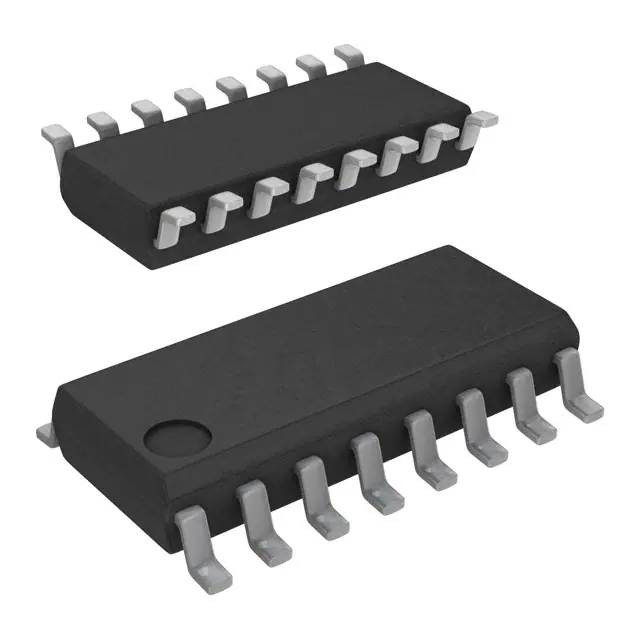
Silicon Labs SI3010-GS
- Part No.:
- SI3010-GS
- Manufacturer:
- Silicon Labs
- Category:
- Telecom
- Package:
- 16-SOIC (0.154", 3.90mm Width)
- Datasheet:
-
SI3010-GS.pdf
- Description:
- IC TELECOM INTERFACE 16SOIC
- Quantity:
- Payment:

- Shipping:

Inventory:1,000
Please send an inquiry. Send us your inquiry, and we will respond immediately.
Product details
Overview
SI3010-GS from Silicon Laboratories is a globally compliant line-side Direct Access Arrangement (DAA) IC designed for telephone line interface in modem and voice systems. It delivers programmable AC/DC termination, 80 dB dynamic range TX/RX paths, >5000 V isolation via proprietary technology, and supports Type I/II caller ID - enabling FCC, TBR21, and JATE regulatory compliance in single-chip DAA solutions.
For engineers reviewing the SI3010-GS datasheet, SI3010-GS pinout, SI3010-GS application, or SI3010-GS equivalent, this page provides verified technical context, real-world design meaning of key specs, validated pin functions, and two confirmed alternative line-side DAAs for global telephony designs requiring regulatory-compliant loop interface, ring detection, and hybrid balance control.
Technical Context
The SI3010-GS operates as the line-side companion to system-side DAAs like the Si3056, forming a complete isolated telephony interface. It implements programmable DC termination (9–40 V range), AC termination, ring detection (13.5–23.65 VRMS, 13–68 Hz), and ringer impedance control - all configurable via serial interface registers. Its isolation barrier meets UL1950 3rd Edition and supports >5000 VRMS withstand voltage.
It integrates transhybrid balance circuitry, polarity reversal detection, loop current monitoring (10–60 mA operating range), and on-hook line monitor functionality. Unlike the Si3056, the SI3010-GS does not include an integrated codec or digital interface clock generation - its role is strictly analog line conditioning and isolation under software control from the system-side device.
Key Specifications
| Parameter | Value and Actual Design Meaning |
|---|---|
| Isolation Voltage | >5000 VRMS - enables single-chip replacement of discrete isolation transformers and opto-isolators in certified telecom designs. |
| Dynamic Range | 80 dB - ensures high-fidelity voice transmission and reception across 300–3400 Hz band with low noise floor in both TX and RX paths. |
| Ring Detect Threshold | 13.5–23.65 VRMS - supports dual-mode ring validation (RT = 0 or 1) for reliable detection across global PTT requirements. |
| Operating Loop Current | 10–60 mA - programmable via ILIM bit to meet regional line power limits (e.g., FCC vs. ETSI). |
| DC Termination Voltage | 9–40 V - adjustable via MINI/DCV/DCR bits to comply with local loop battery voltage standards (e.g., 48 V nominal, 24 V Japan). |
| Ringer Equivalence Number | 0.2 REN - ensures compatibility with standard telephone ringers without overloading central office circuits. |
| Supply Voltage | 3.0–3.6 V - single 3.3 V rail powers all digital logic and charge-pump interfaces, simplifying power architecture. |
Pinout & Package
SI3010-GS is housed in a 16-pin SOIC package (300 mil width), RoHS-compliant and lead-free. Pin functions are defined per Silicon Labs Rev. 1.06 datasheet Section 8 ("Pin Descriptions: Si3018/19/10") - SI3010 shares identical pinout with Si3018/Si3019.
| Pin/Terminal | Circuit Role | Design Meaning |
|---|---|---|
| DCT2 | DC Termination Control 2 | Configures DC termination mode (e.g., constant-current vs. constant-voltage) alongside DCT3 and DCT. |
| IGND | Isolation Ground | Reference for isolated line-side circuitry; must be separated from system-side GND by ≥8 mm creepage/clearance. |
| DCT3 | DC Termination Control 3 | Part of 3-bit DC termination programming group (DCT/DCT2/DCT3) enabling 8 distinct termination profiles. |
| QB | Bridge Quad Output B | One terminal of internal 2-wire to 4-wire hybrid bridge; connects to TIP/RING network via external coupling components. |
| QE2 | Bridge Quad Output E2 | Second hybrid bridge output; used with QE, QB, and SC to implement balanced line drive and echo cancellation. |
| SC | Hybrid Sense Common | Sense node for transhybrid balance calibration; critical for near-end echo reduction in full-duplex operation. |
| VREG2 | Regulated Voltage Output 2 | Provides stable bias for internal analog blocks; requires 1 µF decoupling capacitor per datasheet Figure 17. |
| RNG2 | Ring Detect Output 2 | Secondary ring detect signal path; used with RNG1 for differential validation to reject false triggers. |
| QE | Bridge Quad Output E | Third hybrid bridge output; completes 4-terminal hybrid configuration with QB, QE2, and SC. |
| DCT | DC Termination Control | Primary bit for DC termination selection; works with DCT2/DCT3 to set loop current and voltage targets. |
| RX | Receive Path Input | Analog input from line-side receive path; feeds internal ADC after programmable gain and filtering stages. |
| IB | Loop Current Monitor | Analog output proportional to loop current (10–60 mA); enables real-time supervision and fault detection. |
| C1B | Capacitor Terminal B | Connects to external AC termination capacitor (e.g., 33 pF Y2 ceramic) for impedance matching and EMI suppression. |
| C2B | Capacitor Terminal B2 | Second AC termination node; paired with C1B to form balanced capacitive termination network per ITU-T G.992.x. |
| VREG | Regulated Voltage Output | Main analog supply rail for line interface circuitry; requires 1 µF decoupling and must not be loaded beyond 10 mA. |
| RNG1 | Ring Detect Output 1 | Primary ring detect comparator output; asserted when tip-ring AC voltage exceeds threshold (VRD) for ≥20 ms. |
Key Features
| Feature | Design Value |
|---|---|
| Programmable AC termination | Enables compliance with regional AC impedance requirements (e.g., 600 Ω ±5% for North America, complex Z for Europe) using C1B/C2B external caps. |
| Line voltage and loop current monitoring | Provides real-time analog outputs (IB, VREG) for supervisory MCU to detect off-hook, short-circuit, or open-line faults without external sensors. |
| Polarity reversal detection | Identifies line polarity swaps during call setup - essential for proper operation of polarity-sensitive features like pulse dialing and billing tone detection. |
| Enhanced caller ID support | Meets Type I and II CID standards with 50 dB dynamic range in CID mode and 6 V peak full-scale level for robust data recovery. |
| Proprietary isolation technology | Replaces discrete isolation transformers and optocouplers, reducing BOM count by ≥7 parts and PCB area by >40% versus legacy DAA designs. |
| Low-profile SOIC package | 16-pin 300-mil SOIC footprint allows drop-in replacement of legacy line-side components while maintaining IPC-7351B land pattern compatibility. |
Applications
| V.92 Modems | Voice Mail Systems |
|---|---|
Use Scenario: Integrated dial-up modem in embedded industrial gateway supporting remote diagnostics and firmware updates over PSTN. IC Role / Device Role / Timing Role: Line-side DAA providing isolated, regulated loop interface, ring detection, and hybrid balance for full-duplex V.92 communication. Use Value: Enables FCC-certified modem operation with only two ICs (SI3010-GS + Si3056), eliminating 12+ discrete components including transformer, relays, and AFE. |
Use Scenario: Standalone voice mail unit deployed in small-office PBX environments with analog line interface. IC Role / Device Role / Timing Role: Line-side interface handling on-hook/off-hook detection, caller ID decoding, and echo-cancelled audio capture from PSTN line. Use Value: Supports simultaneous ring detection and voice recording via programmable ring validation (RT=0/1), ensuring no missed messages during high-call-volume periods. |
| Fax Machines | Multi-function Printers |
Use Scenario: Consumer fax machine requiring automatic answer, fax tone detection, and error-free document transmission over global PSTN lines. IC Role / Device Role / Timing Role: Line-side DAA managing loop supervision, pulse/DTMF dialing, and overload protection during fax handshake sequences. Use Value: Programmable DC termination (9–40 V) and AC termination ensure reliable fax transmission across 40+ countries without hardware variants. |
Use Scenario: Office MFP with built-in fax capability connecting directly to analog telephone line without external adapter. IC Role / Device Role / Timing Role: Isolated line interface performing parallel handset detection, billing tone filtering, and transmit/receive gain control for duplex scanning/faxing. Use Value: Integrated polarity reversal detection prevents fax aborts caused by line polarity mismatches - a common failure mode in legacy MFP designs. |
Equivalent & Alternatives
The following parts are listed as comparable options for similar line-side DAA applications.
| Alternative Part | Technical Difference | Application Difference | Selection Advice |
|---|---|---|---|
| Si3018-GS | Identical pinout and register map; differs only in factory-programmed default settings for REN and ring threshold calibration. | Optimized for global PTT compliance out-of-box; SI3010-GS requires software calibration for JATE-specific ring detect thresholds. | Select SI3010-GS when fine-grained control over ring validation timing and hybrid balance coefficients is required in production firmware. |
| Si3019-GS | Includes enhanced caller ID circuitry (62 dB DRCID) and +6.0 dBm TX/RX full-scale mode; otherwise identical line-side functionality. | Required for high-noise environments where CID data integrity must be maintained at -30 dB SNR; SI3010-GS supports only 50 dB DRCID. | Choose SI3019-GS if caller ID reliability in electrically noisy locations (e.g., industrial buildings) is mandatory; SI3010-GS suffices for residential use. |
Compared with Si3018-GS and Si3019-GS, the SI3010-GS offers identical isolation, loop supervision, and hybrid control capabilities but targets cost-sensitive designs where factory-calibrated defaults are unnecessary and firmware-based tuning is preferred for regional certification flexibility.
Availability
SI3010-GS is available at Aetrix Electronics and suitable for V.92 modems, voice mail systems, and fax machines requiring stable component supply, long-term lifecycle support, and guaranteed traceable sourcing for telecom-certified products.
Supply support for SI3010-GS includes scheduled delivery planning, volume procurement assistance, BOM continuity management, traceable sourcing, and lifecycle availability coordination for OEM customers, industrial embedded developers, connected-device designers, and electronics production programs.
Manufacturer
Silicon Laboratories is a fabless semiconductor company specializing in mixed-signal ICs for communications, timing, and human interface applications.
The SI3010-GS belongs to Silicon Labs' Direct Access Arrangement (DAA) product line, engineered to replace analog front ends and isolation transformers in global telephony equipment while meeting stringent safety and emissions standards.
FAQ
What is the primary function of the SI3010-GS in a DAA system?
The SI3010-GS serves as the line-side Direct Access Arrangement IC, providing isolated analog interface to the telephone line - including programmable DC/AC termination, ring detection, loop current monitoring, and hybrid balance control. It pairs exclusively with system-side DAAs like the Si3056, and does not contain a codec or digital interface logic. Its role is strictly physical-layer conditioning and safety isolation.
Does the SI3010-GS support FCC Part 68 and TBR21 certification out of the box?
The SI3010-GS is designed to meet FCC Part 68 and TBR21 requirements when used with the Si3056 system-side DAA and the reference application circuit (Figure 17). Certification depends on full system implementation - including layout, external components (e.g., C1B/C2B values), and software configuration of termination and ring thresholds. Silicon Labs provides pre-certification test reports for the combined Si3056 + SI3010-GS solution.
How does the SI3010-GS differ from the Si3018-GS and Si3019-GS?
The SI3010-GS shares identical pinout, register map, and core functionality with Si3018-GS and Si3019-GS. Differences lie in factory calibration: SI3018-GS ships with global PTT defaults; SI3019-GS adds enhanced caller ID (62 dB DRCID) and +6.0 dBm full-scale mode; SI3010-GS provides maximum firmware configurability with no factory presets - requiring full software calibration for regional compliance.
Can the SI3010-GS operate independently without a system-side DAA like the Si3056?
No. The SI3010-GS is not a standalone device - it requires a system-side DAA (e.g., Si3056) for serial control, clock distribution, digital interface, and codec functions. It has no internal oscillator, no DSP interface, and no digital logic beyond register access. All configuration and data exchange occur via the 3-wire serial interface (SCLK/SDI/SDO) driven by the system-side device.
What is the purpose of the IGNDA and IGNDB pins on the SI3010-GS?
The SI3010-GS does not have IGNDA or IGNDB pins. Its isolation ground is labeled IGND (pin 15), a single dedicated node for the isolated line-side domain. This pin must be routed on a separate PCB layer or isolated copper pour, with ≥8 mm clearance from system-side ground to maintain >5000 VRMS isolation integrity per UL1950. Confusion may arise from misreading "IGND" as plural - it is singular and non-differential.
SI3010-GS Specifications
- Product attributes
- Attribute value
- Manufacturer:
- Silicon Labs
- Series:
- -
- Package/Case:
- 16-SOIC (0.154", 3.90mm Width)
- Packaging:
- Tube
- Product Status:
- Obsolete
- Function:
- Direct Access Arrangement (DAA)
- Interface:
- Parallel, SPI, UART
- Number of Circuits:
- 1
- Voltage - Supply:
- 3V ~ 3.6V
- Current - Supply:
- 15mA
- Power (Watts):
- -
- Operating Temperature:
- 0°C ~ 70°C
- Grade:
- -
- Qualification:
- -
- Mounting Type:
- Surface Mount
- Supplier Device Package:
- 16-SOIC
SI3010-GS FAQ
1.How can I place an order for SI3010-GS through Aetrix?
Please submit a Request for Quotation (RFQ) for SI3010-GS on Aetrix. Our sales agent will provide a competitive quotation and guide you through the order confirmation once you accept the terms.
2.Are the price and stock information for SI3010-GS reliable?
The price and inventory of SI3010-GS are updated periodically and may fluctuate due to market conditions. Stock and pricing data are typically refreshed every 24 hours. Quotation validity for SI3010-GS is usually 5 days.
3.What payment methods are accepted for SI3010-GS?
We accept Wire Transfer, PayPal, Credit Card, Western Union, MoneyGram, and Escrow for SI3010-GS transactions.
Note: Certain payment methods may incur a processing fee.
4.How is shipping managed for SI3010-GS?
SI3010-GS orders can be shipped via leading logistics carriers, including DHL, UPS, FedEx, TNT, or Registered Mail.
Once your SI3010-GS order is processed, you will receive an email with the shipment details and tracking number.
Note: Tracking information may take up to 24 hours to appear. Express delivery typically takes 3–5 business days.
5.How can I obtain technical support or documentation for SI3010-GS?
For technical support, including SI3010-GS datasheets, pinout diagrams, or application guidance, please contact our engineering support team. They can provide detailed documentation and assistance for your SI3010-GS requirements.
6.How does Aetrix verify that SI3010-GS is sourced from the original manufacturer or authorized distributors?
All SI3010-GS products on Aetrix are procured from qualified distributors and authorized channels. Our dedicated quality assurance team conducts strict verification, including traceability checks and, if necessary, third-party testing. This ensures that SI3010-GS meets industry standards.
7.What is the process for return or replacement of SI3010-GS?
All SI3010-GS units undergo pre-shipment inspection (PSI). If there is an issue with SI3010-GS, returns or replacements are accepted under the following conditions:
1.Quantity discrepancies, incorrect items, or visible external defects (such as breakage or corrosion), acknowledged by Aetrix.
2.The issue is reported within 90 days of delivery.
3.The SI3010-GS part is unused and in its original packaging.
Return procedure for SI3010-GS:
1.Submit a request within 90 days.
2.Obtain a Return Material Authorization (RMA) from Aetrix.
SI3010-GS Tags

-
LMC567CMX/NOPB
Texas Instruments

-
LM567CMX/NOPB
Texas Instruments

-
LM567CM/NOPB
Texas Instruments

-
VSC8531XMW-02
Microchip Technology

-
VSC8531XMW-05
Microchip Technology

-
GPY115C0VI
MaxLinear, Inc.

-
SI32185-A-FMR
Skyworks Solutions Inc.

-
VSC8541XMV-05
Microchip Technology

-
SI32178-B-FM1R
Skyworks Solutions Inc.

-
GPY215C0VI
MaxLinear, Inc.

-
CPC7514ZTR
Littelfuse Inc.

-
VSC8502XML-03
Microchip Technology
Tech Hub

Comparator circuit design covering voltage thresholds, input limits, open-collector outputs, LM393 wiring, op-amp differences, hysteresis, timing, window detection and practical fault diagnosis.
Schmitt triggers use separate rising and falling thresholds to stabilize slow or noisy signals. This guide covers hysteresis, 74HC14 and 74HCT14 selection, comparator calculations, RC oscillators and p…
Counterfeit components can hide behind convincing markings and passing basic function tests. This engineering reference covers source traceability, external inspection, X-ray, XRF, electrical testing, …
A practical engineering and sourcing framework covering lifecycle verification, lifetime-buy calculations, replacement qualification, supplier checks and counterfeit-risk controls.
TTL and CMOS logic families differ in thresholds, loading, output drive, power and timing. This engineering guide compares 74HC and 74HCT, calculates noise margins and checks 3.3 V/5 V compatibility.
A practical engineering guide to 3.3V and 5V logic compatibility, input thresholds, resistor dividers, translator ICs, MOSFET level shifting, I2C pull-ups, timing limits and power-sequencing risks.
The 74HC595 uses push-pull logic outputs, while the TPIC6B595 uses 50 V open-drain DMOS sinks for higher-power loads. This guide compares timing, current limits, 3.3 V interfacing, load wiring, thermal…
The 74HC595 converts serial data into eight stable parallel outputs. This guide covers pin functions, shift and storage timing, OE and MR behavior, drive-current limits, cascading, voltage compatibilit…
A technical comparison of level-sensitive latches and edge-triggered flip-flops, covering timing windows, setup and hold limits, master–slave operation, time borrowing, race-through, HDL inference and…
A D latch stores one bit while Enable controls when data can pass. This reference covers gate-level operation, truth tables, transparency, setup and hold timing, LE versus OE, common ICs and practical …