Send an Inquiry

To receive a quote for your project, please fill in the following information, and we’ll get back to you promptly.

Name*
Company*
Email Address*
Phone/WhatsApp
Part Number*
Quantity*
Message
Submit Inventory List

Please fill in the following information, and we’ll get back to you promptly.

Name*
Company*
Email Address*
Phone/WhatsApp
Upload My List
Message

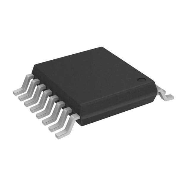
Vishay Siliconix SI9166BQ-T1-E3

Part No.:
SI9166BQ-T1-E3
Manufacturer:
Vishay Siliconix
Category:
Voltage Regulators - DC DC Switching Regulators
Package:
16-TSSOP (0.173", 4.40mm Width)
Datasheet:
AetrixSI9166BQ-T1-E3.pdf
Description:
IC REG BUCK BOOST 1.5A 16TSSOP
Quantity:
Payment:
Payment
Shipping:
Shipping

Inventory:1,339

Please send an inquiry. Send us your inquiry, and we will respond immediately.

Part Number
Quantity*
Price
Name*
Company
Email*
Comments

Product details

Overview

SI9166BQ-T1-E3 from Vishay Siliconix is a high-frequency programmable topology controller supporting synchronous buck or boost DC-DC conversion with voltage-mode control, 2.7–6 V input range for both VDD and VS, up to 2 MHz switching frequency, and <200 µA PSM quiescent current. It serves as the core PWM/PSM controller in portable power systems powering microcontrollers, RF power amplifiers, and baseband logic ICs.

For engineers reviewing the SI9166BQ-T1-E3 datasheet, SI9166BQ-T1-E3 pinout, SI9166BQ-T1-E3 application, or SI9166BQ-T1-E3 equivalent, key selection criteria include topology programmability (buck/boost via MODE pin), dual-mode operation (PWM/PSM), integrated soft-start and UVLO, 1.3 V reference accuracy (±2.4% over temperature), and TSSOP-16 package compatibility with industrial −25°C to +85°C operation.

Technical Context

The SI9166BQ-T1-E3 implements a voltage-mode control architecture with an internal 2 MHz oscillator programmable via ROSC (25 kΩ–300 kΩ), enabling precise duty-cycle regulation across load and line variations. Its error amplifier delivers 2 MHz gain-bandwidth and 3.5 V/sec slew rate to support fast transient response in CCM operation.

Topology selection is hardware-defined: MODE = GND configures buck mode (DH drives high-side p-MOSFET switch; DL drives low-side n-MOSFET synchronous rectifier), while MODE = VDD configures boost mode (DH becomes synchronous rectifier; DL becomes main switch). Break-before-make timing (30 ns) prevents shoot-through, and synchronization (SYNC pin) supports external clock locking within 1.2–1.5× internal frequency.

Key Specifications

ParameterValue and Actual Design Meaning
TopologyProgrammable buck or boost via MODE pin; no external reconfiguration required
Switching Frequency200 kHz–2 MHz; set by ROSC resistor; enables compact 1.5 µH inductors and low-ESR ceramic output caps
VREF Accuracy1.268–1.332 V at IREF = 0 A; ±2.4% tolerance ensures stable feedback loop reference under varying load/temperature
UVLO Threshold2.3–2.5 V turn-on with 0.1 V hysteresis; prevents erratic startup during battery sag
PSM Quiescent Current<200 µA; reduces standby power loss in battery-powered devices during light-load operation
Soft-Start Time6 ms; limits inrush current and prevents output overshoot during power-up
Duty Cycle RangeBuck: up to 85% at 2 MHz (100% max); Boost: up to 65% at 2 MHz (70% max limit to prevent inductor saturation)

Pinout & Package

SI9166BQ-T1-E3 is housed in a lead-free 16-pin TSSOP package (JEDEC MO-153, 5.0 mm × 6.4 mm × 1.2 mm), optimized for surface-mount assembly and thermal performance (θJA = 135°C/W).

Pin/TerminalCircuit RoleDesign Meaning
VSPower supply input for driver stageAccepts 2.7–6 V; powers DH/DL gate drivers independently of analog VDD rail
DHHigh-side gate drive outputDrives p-channel MOSFET gate; functions as main switch in buck, synchronous rectifier in boost
DLLow-side gate drive outputDrives n-channel MOSFET gate; functions as synchronous rectifier in buck, main switch in boost
MODETopology configuration inputLogic low = buck; logic high = boost; determines DH/DL functional assignment
PWM/PSMControl mode selectionLogic high = fixed-frequency PWM; logic low = pulse-skipping mode for ultra-low IQ
FBError amplifier inverting inputConnects to resistive divider from VO; sets regulated output voltage via 1.3 V reference
COMPError amplifier outputInterfaces with external RC compensation network to stabilize loop dynamics
ROSCOscillator timing inputResistor sets switching frequency; 25 kΩ yields ~1.6 MHz; tolerance impacts FSW by ±20%

Key Features

FeatureDesign Value
Synchronous rectification enable/disableAutomatically disabled in PSM mode to eliminate gate charge losses below ~10 mA load
Integrated soft-start and UVLO6 ms ramp time and 2.4 V turn-on threshold ensure controlled, oscillation-free startup from weak batteries
Break-before-make timing30 ns fixed BBM prevents cross-conduction between DH and DL, preserving efficiency and MOSFET reliability
External synchronizationSYNC pin accepts logic-high-to-low edge to align internal oscillator phase with system clock, reducing EMI
Shutdown current<1 µA when SD = low; enables true zero-power state for long-term battery storage

Applications

Mobile Phone Power ManagementWireless Headset Voltage Regulation

Use Scenario: Regulating Li+ battery (3.0–4.2 V) to stable 2.7 V for baseband processor and 3.6 V for RF power amplifier.

IC Role / Device Role / Timing Role: Programmable topology controller managing dual-output synchronous buck/boost conversion with dynamic mode switching.

Use Value: Enables single-chip solution for multi-rail portable power with <200 µA PSM IQ, extending talk time by >15% versus non-PSM controllers.

Use Scenario: Providing regulated 1.8 V and 3.3 V from single NiMH cell (0.9–1.4 V per cell) in Bluetooth headset.

IC Role / Device Role / Timing Role: Boost controller with 2 MHz switching and integrated 1.3 V reference driving external MOSFETs.

Use Value: High-frequency operation allows use of 1.5 µH inductors and 10 µF ceramic caps, reducing solution size by 40% vs. 500 kHz alternatives.

Portable Medical Sensor NodeIndustrial Handheld Scanner

Use Scenario: Powering ultra-low-power MCU (1.8 V) and analog front-end (3.3 V) from coin-cell battery (2.0–3.0 V).

IC Role / Device Role / Timing Role: Buck controller with soft-start and UVLO ensuring clean power-up during cold-start conditions.

Use Value: 6 ms soft-start prevents sensor bias drift; <200 µA PSM current extends shelf life beyond 2 years on CR2032.

Use Scenario: Converting 3.7 V Li-ion pack to 5.0 V for laser diode driver and 1.2 V for ARM Cortex-M4 core.

IC Role / Device Role / Timing Role: Dual-mode controller operating in buck for core rail and boost for peripheral rail, synchronized via SYNC pin.

Use Value: Synchronization eliminates beat frequencies between rails, reducing conducted EMI by >10 dB in 30–100 MHz band.

Equivalent & Alternatives

The following parts are listed as comparable options for similar programmable DC-DC controller applications.

Alternative PartTechnical DifferenceApplication DifferenceSelection Advice
TPS63020DSJRFixed buck-boost topology; no MODE pin; integrated MOSFETs; 2.5–5.5 V input; 1.2–5.5 V outputEliminates external MOSFETs but lacks topology flexibility and programmable frequencySelect when board space is critical and fixed 3.3 V/5 V outputs suffice; not suitable for custom buck-only or boost-only designs
MAX8640YETA+Fixed-frequency (2.25 MHz) buck controller; no PSM mode; requires external MOSFETs; 2.5–5.5 V inputHigher switching frequency but no light-load efficiency optimization; no boost capabilityChoose for high-density buck-only applications where PSM is unnecessary and 2.25 MHz enables smallest passive components

Compared with SI9166BQ-T1-E3, TPS63020DSJR offers integration at the cost of topology and frequency programmability, while MAX8640YETA+ delivers higher frequency without PSM-making SI9166BQ-T1-E3 uniquely suited for battery-powered systems requiring adaptive topology, ultra-low IQ, and design flexibility.

Availability

SI9166BQ-T1-E3 is available at Aetrix Electronics and suitable for mobile phone power management, wireless headset voltage regulation, portable medical sensor nodes, industrial handheld scanners, and battery-backed IoT edge devices requiring stable component supply across extended product lifecycles.

Supply support for SI9166BQ-T1-E3 includes scheduled delivery planning, volume procurement assistance, BOM continuity management, traceable sourcing, and lifecycle availability coordination for OEM customers, industrial embedded developers, connected-device designers, and electronics production programs.

Manufacturer

Vishay Siliconix is a global semiconductor manufacturer specializing in discrete power MOSFETs, diodes, optoelectronics, and analog ICs, with emphasis on high-reliability, high-efficiency power solutions.

The SI9166 family was designed specifically for flexible, high-frequency DC-DC conversion in space-constrained portable electronics, targeting applications requiring programmable topology, low-light-load current, and robust start-up behavior across diverse battery chemistries.

FAQ

What is the maximum supported switching frequency for SI9166BQ-T1-E3, and how is it set?

The SI9166BQ-T1-E3 supports up to 2 MHz switching frequency, set by an external resistor connected to the ROSC pin. A 25 kΩ resistor yields ~1.6 MHz, and values from 25 kΩ to 300 kΩ scale frequency down to 200 kHz. The oscillator tolerance is ±20% with a 1% resistor, making precise frequency setting dependent on ROSC calibration and layout parasitics.

Can SI9166BQ-T1-E3 operate in both buck and boost configurations on the same PCB?

Yes - SI9166BQ-T1-E3 supports hardware-selectable topology: connecting the MODE pin to GND configures buck mode, while connecting it to VDD configures boost mode. This allows a single PCB layout to support either topology via jumper or firmware-controlled GPIO, eliminating redesign for different voltage conversion needs.

What is the purpose of the PWM/PSM pin on SI9166BQ-T1-E3, and how does it affect efficiency?

The PWM/PSM pin selects between fixed-frequency PWM mode (logic high) and pulse-skipping mode (logic low). In PSM, quiescent current drops to <200 µA and synchronous rectification is disabled, improving light-load efficiency by eliminating gate charge losses - critical for battery runtime in intermittent-use devices like remote sensors.

Does SI9166BQ-T1-E3 include built-in protection features, and which ones are active during startup?

Yes - SI9166BQ-T1-E3 integrates under-voltage lockout (UVLO), power-on reset (POR), and soft-start. During startup, UVLO holds the controller inactive until VDD exceeds 2.4–2.5 V; POR enforces a ~1 ms delay before enabling circuits; and soft-start ramps COMP voltage over 6 ms to limit inrush current and prevent output overshoot.

What are the absolute maximum ratings for VS and VDD on SI9166BQ-T1-E3, and why is this distinction important?

VS and VDD each have an absolute maximum rating of 6.5 V, but their recommended operating ranges are 2.7–6 V. VS powers the gate drivers (DH/DL), while VDD powers analog circuitry (error amp, oscillator, reference). Separating these rails allows independent optimization - e.g., VS can be derived from a higher intermediate rail while VDD remains tied to a clean LDO - improving noise immunity and driver strength.

SI9166BQ-T1-E3 Specifications

Product attributes
Attribute value
Manufacturer:
Vishay Siliconix
Series:
-
Package/Case:
16-TSSOP (0.173", 4.40mm Width)
Packaging:
Tape & Reel (TR)
Product Status:
Obsolete
Function:
Step-Up, Step-Down
Output Configuration:
Positive
Topology:
Buck, Boost
Output Type:
-
Number of Outputs:
1
Voltage - Input (Min):
2.7V
Voltage - Input (Max):
6V
Voltage - Output (Min/Fixed):
-
Voltage - Output (Max):
-
Current - Output:
1.5A (Switch)
Frequency - Switching:
200kHz ~ 2MHz
Synchronous Rectifier:
Yes
Operating Temperature:
-25°C ~ 85°C (TA)
Grade:
-
Qualification:
-
Mounting Type:
Surface Mount
Supplier Device Package:
16-TSSOP

SI9166BQ-T1-E3 FAQ

1.How can I place an order for SI9166BQ-T1-E3 through Aetrix?

Please submit a Request for Quotation (RFQ) for SI9166BQ-T1-E3 on Aetrix. Our sales agent will provide a competitive quotation and guide you through the order confirmation once you accept the terms.

2.Are the price and stock information for SI9166BQ-T1-E3 reliable?

The price and inventory of SI9166BQ-T1-E3 are updated periodically and may fluctuate due to market conditions. Stock and pricing data are typically refreshed every 24 hours. Quotation validity for SI9166BQ-T1-E3 is usually 5 days.

3.What payment methods are accepted for SI9166BQ-T1-E3?

We accept Wire Transfer, PayPal, Credit Card, Western Union, MoneyGram, and Escrow for SI9166BQ-T1-E3 transactions.

Note: Certain payment methods may incur a processing fee.

4.How is shipping managed for SI9166BQ-T1-E3?

SI9166BQ-T1-E3 orders can be shipped via leading logistics carriers, including DHL, UPS, FedEx, TNT, or Registered Mail.

Once your SI9166BQ-T1-E3 order is processed, you will receive an email with the shipment details and tracking number.

Note: Tracking information may take up to 24 hours to appear. Express delivery typically takes 3–5 business days.

5.How can I obtain technical support or documentation for SI9166BQ-T1-E3?

For technical support, including SI9166BQ-T1-E3 datasheets, pinout diagrams, or application guidance, please contact our engineering support team. They can provide detailed documentation and assistance for your SI9166BQ-T1-E3 requirements.

6.How does Aetrix verify that SI9166BQ-T1-E3 is sourced from the original manufacturer or authorized distributors?

All SI9166BQ-T1-E3 products on Aetrix are procured from qualified distributors and authorized channels. Our dedicated quality assurance team conducts strict verification, including traceability checks and, if necessary, third-party testing. This ensures that SI9166BQ-T1-E3 meets industry standards.

7.What is the process for return or replacement of SI9166BQ-T1-E3?

All SI9166BQ-T1-E3 units undergo pre-shipment inspection (PSI). If there is an issue with SI9166BQ-T1-E3, returns or replacements are accepted under the following conditions:

1.Quantity discrepancies, incorrect items, or visible external defects (such as breakage or corrosion), acknowledged by Aetrix.

2.The issue is reported within 90 days of delivery.

3.The SI9166BQ-T1-E3 part is unused and in its original packaging.

Return procedure for SI9166BQ-T1-E3:

1.Submit a request within 90 days.

2.Obtain a Return Material Authorization (RMA) from Aetrix.

SI9166BQ-T1-E3 Tags
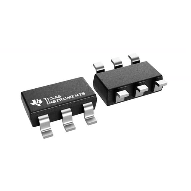
  • SI9166BQ-T1-E3
  • SI9166BQ-T1-E3 PDF
  • SI9166BQ-T1-E3 Datasheet
  • SI9166BQ-T1-E3 Specifications
  • SI9166BQ-T1-E3 Images
  • Vishay Siliconix
  • Vishay Siliconix SI9166BQ-T1-E3
  • Buy SI9166BQ-T1-E3
  • SI9166BQ-T1-E3 Price
  • SI9166BQ-T1-E3 Distributor
  • SI9166BQ-T1-E3 Supplier
  • SI9166BQ-T1-E3 Wholesale
Related Products
TPS562201DDCR
TPS562201DDCR

Texas Instruments

MC34063ABD-TR
MC34063ABD-TR

STMicroelectronics

TPS561201DDCR
TPS561201DDCR

Texas Instruments

MC33063ADR
MC33063ADR

Texas Instruments

MC34063ADR
MC34063ADR

Texas Instruments

TPS560200DBVR
TPS560200DBVR

Texas Instruments

AP3012KTR-G1
AP3012KTR-G1

Diodes Incorporated

TLV61048DBVR
TLV61048DBVR

Texas Instruments

AZ34063UMTR-G1
AZ34063UMTR-G1

Diodes Incorporated

TPS562200DDCR
TPS562200DDCR

Texas Instruments

AP62300TWU-7
AP62300TWU-7

Diodes Incorporated

MC34063EBD-TR
MC34063EBD-TR

STMicroelectronics

Tech Hub

Search

Search

PRODUCT

PRODUCT

PHONE

PHONE

USER

USER