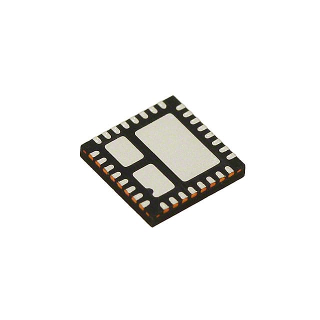
Vishay Siliconix SIC402BCD-T1-GE3
- Part No.:
- SIC402BCD-T1-GE3
- Manufacturer:
- Vishay Siliconix
- Category:
- Voltage Regulators - Linear + Switching
- Package:
- 32-PowerVFQFN
- Datasheet:
-
SIC402BCD-T1-GE3.pdf
- Description:
- IC REG DL BUCK/LNR SYNC MLP55-32
- Quantity:
- Payment:

- Shipping:

Inventory:16,662
Please send an inquiry. Send us your inquiry, and we will respond immediately.
Product details
Overview
SIC402BCD-T1-GE3 from Vishay Siliconix is a 10 A synchronous buck regulator with integrated power MOSFETs, bootstrap switch, and a programmable 200 mA LDO in a PowerPAK® MLP32-55G (5 mm × 5 mm) package. It operates from 3 V to 28 V input, delivers 0.6 V to VIN × 0.75 output, supports 200 kHz–1 MHz switching, and achieves up to 95 % peak efficiency - used for point-of-load regulation in notebook and server CPU core supplies.
For engineers reviewing the SIC402BCD-T1-GE3 datasheet, SIC402BCD-T1-GE3 pinout, SIC402BCD-T1-GE3 application, or SIC402BCD-T1-GE3 equivalent, this page provides verified technical context, validated pin functions, confirmed LDO bypass capability, real-world efficiency curves at 1.5 V/10 A, and authoritative alternative part guidance for embedded power design.
Technical Context
The SIC402BCD-T1-GE3 implements pseudo-fixed-frequency adaptive on-time control using output ripple as the PWM ramp signal, enabling fast transient response without external compensation. Its one-shot timer generates on-time proportional to VOUT and inversely proportional to VIN, with frequency set via an external resistor on the tON pin.
It integrates dual power stages: a main synchronous buck with cycle-by-cycle current limit (programmable via ILIM pin), and a standalone 200 mA LDO with independent ENL enable, selectable VDD sourcing, and VLDO-to-VOUT switch-over logic. Power-save mode (SiC402B variant) disables low-side conduction after 8 consecutive zero-crossing cycles, reducing light-load switching losses.
Key Specifications
| Parameter | Value and Actual Design Meaning |
|---|---|
| Input Voltage Range | 3 V to 28 V - supports wide-input industrial and computing rails including 5 V, 12 V, and 24 V systems. |
| Output Voltage Range | 0.6 V to VIN × 0.75 - enables core voltage regulation down to sub-1 V for modern processors and FPGAs. |
| Continuous Output Current | 10 A - rated for sustained load delivery with thermal derating per RthJA = 50 °C/W. |
| Switching Frequency | 200 kHz to 1 MHz - programmable via tON pin resistor; higher frequencies reduce inductor size but increase switching loss. |
| Peak Efficiency | 95 % - achieved at mid-load (e.g., 5 A) with 12 VIN/1.5 VOUT, enabling high-density thermal design. |
| LDO Output Current | 200 mA - sufficient to bias gate drivers or small peripherals; bypassable via external 5 V supply for optimal system efficiency. |
| Reference Voltage Accuracy | ±1 % - ensures tight output regulation tolerance across temperature and line variations. |
Pinout & Package
Package: PowerPAK® MLP32-55G (5 mm × 5 mm, 32-pin, exposed thermal pad).
| Pin/Terminal | Circuit Role | Design Meaning |
|---|---|---|
| FB | Feedback input | Connects to resistor divider from VOUT to AGND; regulates output by comparing to internal 0.6 V reference. |
| VOUT | Switcher output sense | Senses regulated output; also serves as input to internal LDO/VOUT switch-over logic. |
| VDD | Bias supply input/output | Accepts external 3–5.5 V supply or outputs LDO-regulated voltage; powers internal circuitry. |
| AGND | Analog ground | Reference for FB, FBL, SS, EN/PSV; must be separated from PGND for noise immunity. |
| FBL | LDO feedback input | Programs LDO output voltage via resistor divider from VDD to AGND. |
| VIN | Main input supply | Primary power rail (3–28 V); connected to multiple pins (6, 9–11, PAD2) for low-impedance routing. |
| SS | Soft-start timing | Capacitor-connected node; internal 3 μA current source sets startup ramp time. |
| BST | Bootstrap supply | Requires ≥100 nF capacitor to LX; generates floating gate drive voltage for high-side MOSFET. |
| PGOOD | Open-drain status indicator | Asserts high-impedance when VOUT is within ±10 %/±20 % of target; requires external pull-up. |
| ILIM | Current limit programming | Resistor from ILIM to LXS sets valley current limit threshold (e.g., 4.46 kΩ → 10 A typical). |
| EN/PSV | Enable & power-save control | Logic-level input: grounded = disable, floated = forced continuous, >44 % VDD = power-save mode. |
| ENL | LDO enable | Independent control for LDO; resistor divider from VIN to ENL programs VIN UVLO threshold. |
| tON | On-time programming | Resistor to AGND sets switching frequency; 133 kΩ yields ~300 kHz at VIN = 15 V, VOUT = 5 V. |
| LX | Switching node | Phase node connecting internal high/low-side MOSFETs and external inductor; high di/dt path. |
| PGND | Power ground | High-current return path for MOSFETs and inductor; multiple pins (15–22, PAD1/PAD3) minimize IR drop. |
Key Features
| Feature | Design Value |
|---|---|
| Programmable LDO with bypass logic | 200 mA output configurable as VDD source or disabled to accept external 5 V - eliminates need for discrete bias supply. |
| Adaptive on-time control | Eliminates error amplifier and compensation network; enables <10 μs transient response and stable ceramic-only output filtering. |
| Selectable power-save mode (SiC402B) | Disables low-side MOSFET after 8 zero-crossing cycles - reduces light-load quiescent current to 0.7 mA typical. |
| Independent enable for switcher and LDO | EN/PSV controls buck stage; ENL controls LDO - allows staged power sequencing in multi-rail systems. |
| Programmable input UVLO | VIN undervoltage lockout threshold set via resistor divider on ENL pin (2.4–2.95 V rising threshold). |
| Integrated protection suite | Cycle-by-cycle current limit, over-voltage (±20 %), under-voltage (−25 %), thermal shutdown (150 °C), and soft shutdown. |
Applications
| Server CPU Core Supply | Notebook GPU VRM |
|---|---|
|
Use Scenario: Regulating 0.8–1.3 V core voltage for Intel Xeon or AMD EPYC processors under dynamic 0–10 A load transients. IC Role / Device Role / Timing Role: Primary synchronous buck controller with adaptive on-time loop; delivers precise valley-regulated output using FB feedback. Use Value: 95 % peak efficiency and <10 μs transient response reduce heatsink size and enable tighter output voltage margins. |
Use Scenario: Providing 0.9–1.2 V GPU core power in thin-and-light notebooks with strict thermal and PCB area constraints. IC Role / Device Role / Timing Role: Integrated buck + LDO solution - LDO supplies gate drivers while buck handles high-current GPU loads. Use Value: Single-chip integration eliminates discrete LDO and reduces BOM count; 5 mm × 5 mm MLP32-55G fits dense mobile layouts. |
| Networking ASIC PoL | Industrial FPGA I/O Bank Supply |
|
Use Scenario: Point-of-load conversion for 1.8 V or 2.5 V I/O rails in 10G/25G Ethernet switches with bursty traffic-induced load steps. IC Role / Device Role / Timing Role: High-frequency (up to 1 MHz) buck regulator with programmable soft-start and PGOOD signaling for system monitoring. Use Value: All-ceramic solution enabled by adaptive control reduces ESR dependency; PGOOD enables safe FPGA configuration sequencing. |
Use Scenario: Delivering stable 3.3 V or adjustable I/O voltage to Xilinx or Intel FPGAs in programmable logic controllers with wide ambient temperature range. IC Role / Device Role / Timing Role: Robust buck regulator with −40 °C to +125 °C junction rating, UVLO hysteresis, and thermal shutdown. Use Value: Guaranteed operation across industrial temperature range; programmable UVLO prevents brown-out during unstable 24 V DC input. |
Equivalent & Alternatives
The following parts are listed as comparable options for similar synchronous buck regulator applications.
| Alternative Part | Technical Difference | Application Difference | Selection Advice |
|---|---|---|---|
| MP2315DJ-LF-Z | Monolithic 12 A buck (3–18 VIN, 0.8–15 VOUT); no integrated LDO; fixed 500 kHz fSW; smaller QFN-10 package. | Lacks programmable LDO and independent ENL control - requires external bias supply for gate drivers. | Choose when board space is critical and LDO functionality is provided elsewhere; verify thermal performance at 10 A. |
| TPS54332DR | 12 VIN max, 3 A output, external MOSFETs required; adjustable frequency (100 kHz–2.5 MHz); includes Eco-mode™ for light-load efficiency. | Lower current rating and external power stage increase component count and layout complexity. | Prefer for cost-sensitive designs where 3 A suffices and discrete MOSFET selection is needed for specific RDS(on) or thermal goals. |
Compared with MP2315DJ-LF-Z and TPS54332DR, the SIC402BCD-T1-GE3 uniquely integrates both 10 A power stage and 200 mA LDO in one MLP32-55G package, enabling compact, self-contained PoL solutions without external bias or sequencing components.
Availability
SIC402BCD-T1-GE3 is available at Aetrix Electronics and suitable for server CPU core supplies, notebook GPU VRMs, networking ASIC point-of-load converters, and industrial FPGA I/O banks requiring stable component supply, long-term lifecycle support, and traceable sourcing.
Supply support for SIC402BCD-T1-GE3 includes scheduled delivery planning, volume procurement assistance, BOM continuity management, traceable sourcing, and lifecycle availability coordination for OEM customers, industrial embedded developers, connected-device designers, and electronics production programs.
Manufacturer
Vishay Siliconix is a global leader in discrete semiconductors and passive components, specializing in high-efficiency power management ICs with robust thermal and reliability engineering.
The SiC402 family targets high-density, high-efficiency point-of-load regulation in computing and communications infrastructure, emphasizing integration, adaptive control, and seamless LDO/buck coexistence.
FAQ
What is the key functional difference between SIC402BCD-T1-GE3 and SIC402ACD-T1-GE3?
The SIC402BCD-T1-GE3 implements standard power-save mode that disables low-side conduction after 8 consecutive zero-crossing cycles, while the SIC402ACD-T1-GE3 adds ultrasonic power-save with a minimum 25 kHz frequency floor. Both share identical buck architecture, LDO capability, pinout, and package. The SIC402BCD-T1-GE3 is optimized for maximum light-load efficiency without audible noise constraints.
Can the internal LDO in SIC402BCD-T1-GE3 be completely disabled and bypassed?
Yes - the SIC402BCD-T1-GE3 LDO is fully bypassable. Drive ENL low to disable the LDO, then apply a clean 3–5.5 V external supply directly to the VDD pin. This configuration eliminates LDO dropout loss and improves overall system efficiency, especially when an external 5 V rail is already available for gate driving or other peripherals.
What is the recommended layout practice for AGND and PGND in SIC402BCD-T1-GE3 designs?
Separate AGND (pins 1, 4, 30, PAD1) and PGND (pins 15–22, PAD1/PAD3) planes must be joined at a single point near the IC's thermal pad. AGND carries low-current analog references (FB, FBL, SS); PGND carries high di/dt switching currents. Routing high-current PGND traces directly under the IC minimizes loop inductance, while AGND traces avoid crossing noisy PGND regions to preserve feedback accuracy.
How is the switching frequency programmed on SIC402BCD-T1-GE3?
The SIC402BCD-T1-GE3 uses the tON pin (pin 31) for frequency programming: connect a resistor RtON from tON to AGND. For example, 133 kΩ sets ~300 kHz at VIN = 15 V and VOUT = 5 V. The relationship is tON = k × RtON × (VOUT/VIN), where k = 1 if VDD > 3.6 V. Maximum RtON is limited by minimum on-time (80 ns) and VINMIN.
Does SIC402BCD-T1-GE3 support pre-biased output startup?
Yes - the SIC402BCD-T1-GE3 supports pre-biased startup. When EN/PSV is asserted while VOUT is already above regulation, the controller enters a controlled start-up sequence: it monitors VFB and initiates DH pulses only after VFB falls below the 0.6 V reference, preventing reverse inductor current and output overshoot. This behavior is confirmed in Figure 14 and Figure 15 of the datasheet.
SIC402BCD-T1-GE3 Specifications
- Product attributes
- Attribute value
- Manufacturer:
- Vishay Siliconix
- Series:
- microBUCK®
- Package/Case:
- 32-PowerVFQFN
- Packaging:
- Tape & Reel (TR)
- Product Status:
- Obsolete
- Topology:
- Step-Down (Buck) Synchronous (1), Linear (LDO) (1)
- Number of Outputs:
- 2
- Frequency - Switching:
- 200kHz ~ 1MHz
- Voltage/Current - Output 1:
- 0.6V ~ 5.5V, 10A
- Voltage/Current - Output 2:
- Adj to 0.75V, 200mA
- Voltage/Current - Output 3:
- -
- w/LED Driver:
- No
- w/Supervisor:
- No
- w/Sequencer:
- No
- Voltage - Supply:
- 3V ~ 28V
- Operating Temperature:
- -40°C ~ 85°C
- Grade:
- -
- Qualification:
- -
- Mounting Type:
- Surface Mount
- Supplier Device Package:
- PowerPAK® MLP55-32
SIC402BCD-T1-GE3 FAQ
1.How can I place an order for SIC402BCD-T1-GE3 through Aetrix?
Please submit a Request for Quotation (RFQ) for SIC402BCD-T1-GE3 on Aetrix. Our sales agent will provide a competitive quotation and guide you through the order confirmation once you accept the terms.
2.Are the price and stock information for SIC402BCD-T1-GE3 reliable?
The price and inventory of SIC402BCD-T1-GE3 are updated periodically and may fluctuate due to market conditions. Stock and pricing data are typically refreshed every 24 hours. Quotation validity for SIC402BCD-T1-GE3 is usually 5 days.
3.What payment methods are accepted for SIC402BCD-T1-GE3?
We accept Wire Transfer, PayPal, Credit Card, Western Union, MoneyGram, and Escrow for SIC402BCD-T1-GE3 transactions.
Note: Certain payment methods may incur a processing fee.
4.How is shipping managed for SIC402BCD-T1-GE3?
SIC402BCD-T1-GE3 orders can be shipped via leading logistics carriers, including DHL, UPS, FedEx, TNT, or Registered Mail.
Once your SIC402BCD-T1-GE3 order is processed, you will receive an email with the shipment details and tracking number.
Note: Tracking information may take up to 24 hours to appear. Express delivery typically takes 3–5 business days.
5.How can I obtain technical support or documentation for SIC402BCD-T1-GE3?
For technical support, including SIC402BCD-T1-GE3 datasheets, pinout diagrams, or application guidance, please contact our engineering support team. They can provide detailed documentation and assistance for your SIC402BCD-T1-GE3 requirements.
6.How does Aetrix verify that SIC402BCD-T1-GE3 is sourced from the original manufacturer or authorized distributors?
All SIC402BCD-T1-GE3 products on Aetrix are procured from qualified distributors and authorized channels. Our dedicated quality assurance team conducts strict verification, including traceability checks and, if necessary, third-party testing. This ensures that SIC402BCD-T1-GE3 meets industry standards.
7.What is the process for return or replacement of SIC402BCD-T1-GE3?
All SIC402BCD-T1-GE3 units undergo pre-shipment inspection (PSI). If there is an issue with SIC402BCD-T1-GE3, returns or replacements are accepted under the following conditions:
1.Quantity discrepancies, incorrect items, or visible external defects (such as breakage or corrosion), acknowledged by Aetrix.
2.The issue is reported within 90 days of delivery.
3.The SIC402BCD-T1-GE3 part is unused and in its original packaging.
Return procedure for SIC402BCD-T1-GE3:
1.Submit a request within 90 days.
2.Obtain a Return Material Authorization (RMA) from Aetrix.
SIC402BCD-T1-GE3 Tags

-
TPS6521905RHBR
Texas Instruments
-
MIC3385YHL-TR
Microchip Technology
-
A4402ELPTR-T
Allegro MicroSystems

-
LM26480SQ-AA/NOPB
Texas Instruments

-
A4402KLPTR-T
Allegro MicroSystems
-
BD71847AMWV-E2
ROHM Semiconductor
-
ADP5040ACPZ-1-R7
Analog Devices Inc.
-
LT3048IDC#TRPBF
Analog Devices Inc.
-
ADP5037ACPZ-R7
Analog Devices Inc.

-
XRP7714ILB-F
MaxLinear, Inc.
-
LTC3260EDE#TRPBF
Analog Devices Inc.
-
LTC3260EMSE#PBF
Analog Devices Inc.
Tech Hub

Comparator circuit design covering voltage thresholds, input limits, open-collector outputs, LM393 wiring, op-amp differences, hysteresis, timing, window detection and practical fault diagnosis.
Schmitt triggers use separate rising and falling thresholds to stabilize slow or noisy signals. This guide covers hysteresis, 74HC14 and 74HCT14 selection, comparator calculations, RC oscillators and p…
Counterfeit components can hide behind convincing markings and passing basic function tests. This engineering reference covers source traceability, external inspection, X-ray, XRF, electrical testing, …
A practical engineering and sourcing framework covering lifecycle verification, lifetime-buy calculations, replacement qualification, supplier checks and counterfeit-risk controls.
TTL and CMOS logic families differ in thresholds, loading, output drive, power and timing. This engineering guide compares 74HC and 74HCT, calculates noise margins and checks 3.3 V/5 V compatibility.
A practical engineering guide to 3.3V and 5V logic compatibility, input thresholds, resistor dividers, translator ICs, MOSFET level shifting, I2C pull-ups, timing limits and power-sequencing risks.
The 74HC595 uses push-pull logic outputs, while the TPIC6B595 uses 50 V open-drain DMOS sinks for higher-power loads. This guide compares timing, current limits, 3.3 V interfacing, load wiring, thermal…
The 74HC595 converts serial data into eight stable parallel outputs. This guide covers pin functions, shift and storage timing, OE and MR behavior, drive-current limits, cascading, voltage compatibilit…
A technical comparison of level-sensitive latches and edge-triggered flip-flops, covering timing windows, setup and hold limits, master–slave operation, time borrowing, race-through, HDL inference and…
A D latch stores one bit while Enable controls when data can pass. This reference covers gate-level operation, truth tables, transparency, setup and hold timing, LE versus OE, common ICs and practical …