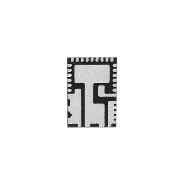
Vishay Siliconix SIC451ED-T1-GE3
- Part No.:
- SIC451ED-T1-GE3
- Manufacturer:
- Vishay Siliconix
- Package:
- 34-PowerWFQFN
- Datasheet:
-
SIC451ED-T1-GE3.pdf
- Description:
- IC REG BCK ADJ POWERPAK MLP34-57
- Quantity:
- Payment:

- Shipping:

Inventory:4,271
Please send an inquiry. Send us your inquiry, and we will respond immediately.
Product details
Overview
SIC451ED-T1-GE3 from Vishay Siliconix is a PMBus 1.3–compliant, non-isolated synchronous buck DC/DC converter with integrated 4 mΩ high-side and 1.4 mΩ low-side MOSFETs. It delivers up to 25 A continuous output current (≥30 A at VOUT < 2.5 V), supports 0.3–12 V digitally adjustable output voltage from a 4.5–20 V input, and operates up to 1.5 MHz switching frequency. It is used in server point-of-load power delivery where fast transient response, telemetry, and digital configuration are required.
For engineers reviewing the SIC451ED-T1-GE3 datasheet, SIC451ED-T1-GE3 pinout, SIC451ED-T1-GE3 application, or SIC451ED-T1-GE3 equivalent, key selection considerations include its 25 A rated current, MLP34-57 package footprint, PMBus-configurable fault thresholds, differential remote sensing capability, and voltage-mode COT control architecture enabling ultrafast load-step response without external compensation.
Technical Context
The SIC451ED-T1-GE3 implements a voltage-mode constant-on-time (VM-COT) control scheme with internal ramp generation and error amplifier compensation. Its control loop requires no external RC network and remains stable with any output capacitor type due to integrated compensation and automatic RAMP scaling based on VOUT and fSW.
It integrates full telemetry (PVIN, VOUT, IIN, IOUT, temperature), pulse-by-pulse overcurrent protection with programmable valley-current threshold, and configurable protections including OVP/UVP, OTP, VIN-OVP/UVP, and tON-MAX. All fault responses-including delay times, hysteresis, and restart behavior-are set via PMBus commands and stored in 1 kB NVM.
Key Specifications
| Parameter | Value and Actual Design Meaning |
|---|---|
| Input Voltage Range | 4.5 V to 20 V - Supports wide industrial and server rail inputs; UVLO thresholds at 9 V (turn-on) and 10 V (turn-off) default. |
| Output Current Rating | 25 A continuous (≥30 A at VOUT < 2.5 V) - Enables single-chip DDR memory or ASIC core rail supply without parallel devices. |
| Output Voltage Range | 0.3 V to 12 V - Digitally adjustable in 2 mV steps via PMBus; resistor-programmable from VSET pin with ±1 % accuracy over temp. |
| Switching Frequency | 300 kHz to 1.5 MHz - Set by RT/SYNC resistor or overridden via PMBus; supports phase synchronization in master/slave configurations. |
| Efficiency | 98 % peak - Achieved using integrated low-RDS(on) MOSFETs (4 mΩ HS / 1.4 mΩ LS) and adaptive light-load diode emulation + frequency foldback. |
| Protection Features | Pulse-by-pulse OCP, OVP/UVP, VIN-OVP/UVP, OTP, tON-MAX - All thresholds and response delays fully programmable and stored in NVM. |
| Telemetry Accuracy | VOUT monitoring ±1 %, IOUT ±3 %, PVIN ±3 % - Enables real-time power budgeting and health monitoring in server BMC systems. |
Pinout & Package
Package: PowerPAK® MLP34-57 (5 mm × 7 mm, 34-pin exposed pad). Thermally enhanced for high-current operation with RthJ-PCB = 5 °C/W.
| Pin/Terminal | Circuit Role | Design Meaning |
|---|---|---|
| PVIN (1,2,3,34) | Power input supply for MOSFET stage | Accepts 4.5–20 V; connects directly to high-current input bulk capacitors; shared with PH and SW nodes for low-inductance layout. |
| PH (4), SW (26–31) | Phase node / switch node | High dv/dt node connecting HS drain and LS source; requires tight coupling to inductor and minimal loop area for EMI control. |
| BOOT (6) | Bootstrap supply for HS gate driver | Referenced to PH; requires 0.1 µF ceramic capacitor between BOOT and PH to sustain HS FET turn-on during high-duty-cycle operation. |
| VSEN+ (12), VSEN− (11) | Differential remote sense inputs | Enable precise regulation at load point; reject PCB IR drop; support Kelvin connection to output capacitor or load plane. |
| PGOOD (13) | Open-drain power-good indicator | Signals VOUT within ±5 % of setpoint (default); requires external 10 kΩ pull-up to VDD; 25 µs rise/fall delay ensures glitch immunity. |
| RT/SYNC (17) | Frequency setting / clock sync interface | Resistor-to-AGND sets fSW (300–1500 kHz); also accepts or generates sync clock for interleaving up to 180° out-of-phase operation. |
| SDA/SCL (19,20) | PMBus 1.3 data/clock lines | Support 1 MHz bus speed; enable full configuration, telemetry readback, and fault logging without additional MCU firmware. |
| EN (21) | Enable control input | Active-high 5 V logic; no sequencing requirement with PVIN/VDD; enables clean power sequencing in multi-rail systems. |
Key Features
| Feature | Design Value |
|---|---|
| Integrated Power Stage | 4 mΩ HS + 1.4 mΩ LS MOSFETs - Eliminates external FETs and drivers; reduces BOM count and layout complexity for 25 A PoL designs. |
| VM-COT Control with No External Compensation | Fully internal ramp and error amplifier - Guarantees stability across all VOUT/fSW combinations and capacitor types; removes need for RCOMP/CCOMP. |
| Digital Configuration & Telemetry | 1 kB NVM storage + 50+ PMBus commands - Stores startup defaults, fault thresholds, and telemetry calibration; enables field firmware updates and runtime reconfiguration. |
| Adaptive Light-Load Efficiency | Diode emulation + frequency foldback - Maintains >85 % efficiency at 1 % load; avoids audible noise by supporting ultrasonic mode (>20 kHz minimum fSW). |
| Differential Remote Sensing | VSEN+/VSEN− inputs with ±200 mV common-mode range - Compensates for PCB voltage drop; ensures ±1 % regulation accuracy at point-of-load under dynamic current steps. |
Applications
| Server Core Voltage Regulation | DDR5 Memory Power Delivery |
|---|---|
Use Scenario: Regulating 1.1 V core voltage for high-performance x86 CPUs in dual-socket servers with rapid load transients up to 100 A/µs. IC Role / Device Role / Timing Role: Primary synchronous buck regulator with PMBus telemetry feeding server BMC for real-time thermal/power management. Use Value: Ultrafast VM-COT response minimizes required output capacitance; integrated MOSFETs reduce solution size vs. controller+FET discrete design. |
Use Scenario: Supplying 1.1 V VDDQ and 1.8 V VPP rails to DDR5 modules with tight voltage tolerance (±3 %) and dynamic current demands. IC Role / Device Role / Timing Role: Digitally programmable point-of-load converter with differential sensing to maintain regulation at memory DIMM pins. Use Value: 2 mV VOUT resolution and ±1 % accuracy ensure compliance with JEDEC DDR5 VDDQ spec; remote sense rejects board-level IR drop. |
| Telecom Baseband Processing | AI Accelerator Card Power |
Use Scenario: Providing 0.8 V @ 20 A to FPGA-based baseband processors in 5G radio units with strict EMI and thermal constraints. IC Role / Device Role / Timing Role: High-density buck regulator synchronized via RT/SYNC to avoid beat frequencies in multi-phase systems. Use Value: 1.5 MHz max fSW enables small inductors; MLP34-57 package supports double-sided PCB assembly for thermal relief. |
Use Scenario: Delivering 0.75 V @ 25 A to GPU or TPU cores on PCIe accelerator cards with dynamic power capping requirements. IC Role / Device Role / Timing Role: Telemetry-enabled regulator reporting real-time POUT, IOUT, and die temperature to host system for dynamic voltage/frequency scaling. Use Value: Integrated power monitoring (±3 % accuracy) replaces external sense resistors and ADCs; reduces component count and measurement error. |
Equivalent & Alternatives
The following parts are listed as comparable options for similar synchronous buck regulator applications.
| Alternative Part | Technical Difference | Application Difference | Selection Advice |
|---|---|---|---|
| MP8772GQ-Z (Monolithic Power Systems) | 40 V max input, 20 A rating, no PMBus; analog-only configuration via resistor networks and EN/PGOOD only. | Lacks telemetry, digital configuration, and NVM; suitable for cost-sensitive, fixed-output industrial supplies without system-level monitoring. | Select MP8772GQ-Z only if PMBus telemetry, remote sensing, and programmable fault response are unnecessary. |
| TPS546D24RVR (Texas Instruments) | Same 25 A rating, 4.5–18 V input, PMBus 1.3 compliant, but uses different pinout (32-pin QFN) and lacks integrated VDD LDO. | Requires external 5 V bias supply; supports higher VIN-OVP (20 V) but offers fewer stored configurations in NVM (256 bytes vs. 1 kB). | Choose TPS546D24RVR when leveraging TI's Fusion Digital Power Designer toolchain is preferred over Vishay's PowerNavigator compatibility. |
Compared with MP8772GQ-Z and TPS546D24RVR, the SIC451ED-T1-GE3 uniquely combines 25 A capability with full PMBus telemetry, differential remote sensing, and 1 kB NVM for autonomous fault recovery-making it optimal for server and AI infrastructure where visibility and configurability are critical.
Availability
SIC451ED-T1-GE3 is available at Aetrix Electronics and suitable for server motherboard power delivery, DDR5 memory subsystems, and telecom baseband processing requiring stable component supply, long-term lifecycle support, and traceable sourcing.
Supply support for SIC451ED-T1-GE3 includes scheduled delivery planning, volume procurement assistance, BOM continuity management, traceable sourcing, and lifecycle availability coordination for OEM customers, industrial embedded developers, connected-device designers, and electronics production programs.
Manufacturer
Vishay Siliconix is a global leader in discrete semiconductors and passive components, specializing in high-efficiency power solutions for computing, industrial, and communications markets.
The SiC45x family-including SIC451ED-T1-GE3-is designed specifically for high-current, digitally managed point-of-load applications in cloud infrastructure, where PMBus configurability, telemetry, and compact MLP packaging are essential.
FAQ
What is the maximum continuous output current supported by the SIC451ED-T1-GE3?
The SIC451ED-T1-GE3 supports 25 A continuous output current across its full operating temperature range (–40 °C to +125 °C junction). At output voltages below 2.5 V, it can deliver up to 30 A continuously. This rating is validated with proper thermal management using the MLP34-57 package's exposed pad and recommended PCB copper area per Vishay's layout guidelines.
Does the SIC451ED-T1-GE3 require external compensation components?
No, the SIC451ED-T1-GE3 does not require external compensation components. Its voltage-mode COT control architecture integrates all necessary ramp generation, error amplification, and compensation circuitry internally. Stability is guaranteed across the full 0.3–12 V output range and 300 kHz–1.5 MHz switching frequency range with any output capacitor type.
How is output voltage configured on the SIC451ED-T1-GE3?
Output voltage on the SIC451ED-T1-GE3 can be set either by connecting a resistor from the VSET pin to AGND (supporting 14 standard voltages from 0.6 V to 12 V) or digitally via PMBus commands. The PMBus method provides 2 mV resolution and independent programming of warning/fault thresholds, while the resistor method achieves ±1 % accuracy over temperature without host communication.
What protection features are implemented in the SIC451ED-T1-GE3?
The SIC451ED-T1-GE3 implements pulse-by-pulse overcurrent protection, output overvoltage/undervoltage protection, input overvoltage/undervoltage protection, overtemperature protection with hysteresis, and tON-MAX fault detection. All protection thresholds and response behaviors-including delay times and restart attempts-are fully programmable via PMBus and stored in non-volatile memory.
Is the SIC451ED-T1-GE3 compatible with other devices in the SiC45x family for pin-to-pin replacement?
No, the SIC451ED-T1-GE3 is not pin-to-pin compatible with SiC450ED-T1-GE3 or SiC453ED-T1-GE3. While all share the same MLP34-57 package and pinout, their current ratings (40 A / 25 A / 15 A) reflect different internal MOSFET RDS(on) values and thermal design margins. Substitution requires validation of thermal performance, current capability, and fault threshold settings for the target application.
SIC451ED-T1-GE3 Specifications
- Product attributes
- Attribute value
- Manufacturer:
- Vishay Siliconix
- Series:
- microBUCK®
- Package/Case:
- 34-PowerWFQFN
- Packaging:
- Tape & Reel (TR)
- Product Status:
- Active
- Function:
- Step-Down
- Output Configuration:
- Positive
- Topology:
- Buck
- Output Type:
- Adjustable
- Number of Outputs:
- 1
- Voltage - Input (Min):
- 4.5V
- Voltage - Input (Max):
- 20V
- Voltage - Output (Min/Fixed):
- 0.3V
- Voltage - Output (Max):
- 12V
- Current - Output:
- 25A
- Frequency - Switching:
- 300kHz ~ 1.5MHz
- Synchronous Rectifier:
- Yes
- Operating Temperature:
- -40°C ~ 85°C (TA)
- Grade:
- -
- Qualification:
- -
- Mounting Type:
- Surface Mount
- Supplier Device Package:
- PowerPAK® MLP34-57
SIC451ED-T1-GE3 FAQ
1.How can I place an order for SIC451ED-T1-GE3 through Aetrix?
Please submit a Request for Quotation (RFQ) for SIC451ED-T1-GE3 on Aetrix. Our sales agent will provide a competitive quotation and guide you through the order confirmation once you accept the terms.
2.Are the price and stock information for SIC451ED-T1-GE3 reliable?
The price and inventory of SIC451ED-T1-GE3 are updated periodically and may fluctuate due to market conditions. Stock and pricing data are typically refreshed every 24 hours. Quotation validity for SIC451ED-T1-GE3 is usually 5 days.
3.What payment methods are accepted for SIC451ED-T1-GE3?
We accept Wire Transfer, PayPal, Credit Card, Western Union, MoneyGram, and Escrow for SIC451ED-T1-GE3 transactions.
Note: Certain payment methods may incur a processing fee.
4.How is shipping managed for SIC451ED-T1-GE3?
SIC451ED-T1-GE3 orders can be shipped via leading logistics carriers, including DHL, UPS, FedEx, TNT, or Registered Mail.
Once your SIC451ED-T1-GE3 order is processed, you will receive an email with the shipment details and tracking number.
Note: Tracking information may take up to 24 hours to appear. Express delivery typically takes 3–5 business days.
5.How can I obtain technical support or documentation for SIC451ED-T1-GE3?
For technical support, including SIC451ED-T1-GE3 datasheets, pinout diagrams, or application guidance, please contact our engineering support team. They can provide detailed documentation and assistance for your SIC451ED-T1-GE3 requirements.
6.How does Aetrix verify that SIC451ED-T1-GE3 is sourced from the original manufacturer or authorized distributors?
All SIC451ED-T1-GE3 products on Aetrix are procured from qualified distributors and authorized channels. Our dedicated quality assurance team conducts strict verification, including traceability checks and, if necessary, third-party testing. This ensures that SIC451ED-T1-GE3 meets industry standards.
7.What is the process for return or replacement of SIC451ED-T1-GE3?
All SIC451ED-T1-GE3 units undergo pre-shipment inspection (PSI). If there is an issue with SIC451ED-T1-GE3, returns or replacements are accepted under the following conditions:
1.Quantity discrepancies, incorrect items, or visible external defects (such as breakage or corrosion), acknowledged by Aetrix.
2.The issue is reported within 90 days of delivery.
3.The SIC451ED-T1-GE3 part is unused and in its original packaging.
Return procedure for SIC451ED-T1-GE3:
1.Submit a request within 90 days.
2.Obtain a Return Material Authorization (RMA) from Aetrix.
SIC451ED-T1-GE3 Tags
-
TPS562201DDCR
Texas Instruments

-
MC34063ABD-TR
STMicroelectronics

-
TPS561201DDCR
Texas Instruments

-
MC33063ADR
Texas Instruments

-
MC34063ADR
Texas Instruments

-
TPS560200DBVR
Texas Instruments
-
AP3012KTR-G1
Diodes Incorporated
-
TLV61048DBVR
Texas Instruments

-
AZ34063UMTR-G1
Diodes Incorporated

-
TPS562200DDCR
Texas Instruments
-
AP62300TWU-7
Diodes Incorporated

-
MC34063EBD-TR
STMicroelectronics
Tech Hub

Comparator circuit design covering voltage thresholds, input limits, open-collector outputs, LM393 wiring, op-amp differences, hysteresis, timing, window detection and practical fault diagnosis.
Schmitt triggers use separate rising and falling thresholds to stabilize slow or noisy signals. This guide covers hysteresis, 74HC14 and 74HCT14 selection, comparator calculations, RC oscillators and p…
Counterfeit components can hide behind convincing markings and passing basic function tests. This engineering reference covers source traceability, external inspection, X-ray, XRF, electrical testing, …
A practical engineering and sourcing framework covering lifecycle verification, lifetime-buy calculations, replacement qualification, supplier checks and counterfeit-risk controls.
TTL and CMOS logic families differ in thresholds, loading, output drive, power and timing. This engineering guide compares 74HC and 74HCT, calculates noise margins and checks 3.3 V/5 V compatibility.
A practical engineering guide to 3.3V and 5V logic compatibility, input thresholds, resistor dividers, translator ICs, MOSFET level shifting, I2C pull-ups, timing limits and power-sequencing risks.
The 74HC595 uses push-pull logic outputs, while the TPIC6B595 uses 50 V open-drain DMOS sinks for higher-power loads. This guide compares timing, current limits, 3.3 V interfacing, load wiring, thermal…
The 74HC595 converts serial data into eight stable parallel outputs. This guide covers pin functions, shift and storage timing, OE and MR behavior, drive-current limits, cascading, voltage compatibilit…
A technical comparison of level-sensitive latches and edge-triggered flip-flops, covering timing windows, setup and hold limits, master–slave operation, time borrowing, race-through, HDL inference and…
A D latch stores one bit while Enable controls when data can pass. This reference covers gate-level operation, truth tables, transparency, setup and hold timing, LE versus OE, common ICs and practical …