Send an Inquiry

To receive a quote for your project, please fill in the following information, and we’ll get back to you promptly.

Name*
Company*
Email Address*
Phone/WhatsApp
Part Number*
Quantity*
Message
Submit Inventory List

Please fill in the following information, and we’ll get back to you promptly.

Name*
Company*
Email Address*
Phone/WhatsApp
Upload My List
Message

Vishay Siliconix SIC472ED-T1-GE3

Part No.:
SIC472ED-T1-GE3
Manufacturer:
Vishay Siliconix
Category:
Voltage Regulators - DC DC Switching Regulators
Package:
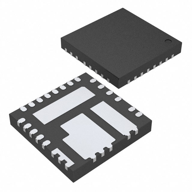
PowerPAK® MLP55-27
Datasheet:
AetrixSIC472ED-T1-GE3.pdf
Description:
IC REG BCK ADJ POWERPAK MLP55-27
Quantity:
Payment:
Payment
Shipping:
Shipping

Inventory:3,800

Please send an inquiry. Send us your inquiry, and we will respond immediately.

Part Number
Quantity*
Price
Name*
Company
Email*
Comments

Product details

Overview

SIC472ED-T1-GE3 from Vishay Siliconix is an 8 A, 4.5 V to 55 V input synchronous buck DC/DC converter with integrated high-side and low-side MOSFETs, adjustable 0.8 V output, and 2 MHz max switching frequency-designed for industrial computing, telecom power supplies, and robotics where wide VIN range and fast transient response are critical.

For engineers reviewing the SIC472ED-T1-GE3 datasheet, SIC472ED-T1-GE3 pinout, SIC472ED-T1-GE3 application, or SIC472ED-T1-GE3 equivalent, key selection considerations include its MLP55-27L package, valley current limit programmability via ILIMIT pin, ultrasonic mode control, ±1 % VFB accuracy over –40 °C to +125 °C, and compatibility with ceramic output capacitors without external ESR requirements.

Technical Context

The SIC472ED-T1-GE3 implements a voltage-mode constant-on-time (COT) control architecture with adaptive zero-current detection, enabling stable operation across discontinuous (DCM), continuous (CCM), and ultrasonic modes without capacitor-type dependency. Its internal error amplifier (gm = 0.3 mS) and dedicated VSNS pin support ripple-injection-based feedforward compensation for sub-100 ns transient response.

Power stage integration includes a 20 mΩ high-side and 8 mΩ low-side n-channel MOSFET pair optimized for 98 % peak efficiency at 48 VIN/5 VOUT. Protection logic executes pulse-by-pulse OCP, auto-retry UVP/OVP, and thermal shutdown with 150 °C trip and 35 °C hysteresis-fully managed by analog circuitry without microcontroller intervention.

Key Specifications

Parameter Value and Actual Design Meaning
Output Current 8 A continuous - supports single-rail conversion for mid-power industrial loads without external current sharing.
Input Voltage Range 4.5 V to 55 V - enables direct connection to 12 V, 24 V, 48 V, and unregulated wall adapters without pre-regulation.
Feedback Accuracy ±1 % from –40 °C to +125 °C - ensures tight regulation in automotive under-hood and industrial ambient conditions.
Switching Frequency 100 kHz to 2 MHz (programmable via fSW pin resistor) - allows EMI optimization and size reduction using small inductors.
High-Side RDS(on) 20 mΩ @ VDRV = 5.3 V, TA = 25 °C - minimizes conduction loss at 8 A, contributing to >95 % efficiency at 1 A load.
Soft-Start Current 5 μA (typ.) - sets precise ramp rate with external capacitor; avoids inrush-induced rail collapse in multi-rail systems.
Shutdown Current 4 μA (max) - enables ultra-low quiescent power in battery-backed or always-on standby subsystems.

Pinout & Package

Package: PowerPAK® MLP55-27L (5 mm × 5 mm, 27-pin lead-free QFN with exposed thermal pad).

Pin/Terminal Circuit Role Design Meaning
1 VCIN Bias supply input for internal regulators Accepts 4.5–55 V; decoupled separately from VIN to reduce LDO losses when VIN > 5 V.
2 PGOOD Open-drain power-good flag Signals valid regulation (VFB ≥ 0.8 V + 20 %); requires external pull-up for system sequencing.
3 EN Enable control High-voltage compatible (0–55 V); internal 5 MΩ pulldown prevents floating startup.
4 BOOT High-side gate driver bootstrap Charged via external diode/capacitor; enables full enhancement of high-side MOSFET.
5,6 PHASE High-side source / low-side drain node Connects directly to inductor; carries full switching current and must be routed with low-inductance layout.
7–8,29 VIN Main power stage input Parallel pins reduce IR drop and thermal stress; ties to bulk input capacitor for low-impedance path.
9–11,17,30 PGND Power ground return Multiple pins minimize ground bounce; must connect to thermal pad and input/output capacitor grounds.
12–14 SW Switch node Drives inductor; high dV/dt node requiring tight loop area and guard ring to reduce EMI.
15 GL Low-side gate drive output Directly drives low-side MOSFET gate; not user-accessible-internal only.
16 VDRV Gate driver supply output LDO output (5.3 V typ.); 4.7 μF decoupling required; can be bypassed with external 5 V supply in Mode 3/4.
18 ULTRASONIC Ultrasonic mode enable Tie to VDD for >20 kHz min. frequency (audible-noise avoidance); float to disable and allow sub-kHz DCM.
19 SS Soft-start timing 5 μA internal current charges external capacitor; sets monotonic VOUT ramp time.
20 VSNS Ripple injection feedback Enables stable COT control with ceramic caps; requires Rx/Cx/Cy network per VRAMP amplitude spec (100–900 mV).
21 COMP Error amplifier output Connects to RCOMP/CCOMP network; sets loop gain/phase margin independent of output cap ESR.
22 VFB Feedback input 0.8 V reference point; connects to resistor divider from VOUT; ±1 % accuracy enables precision output setting.
23,28 AGND Analog ground reference Separate from PGND; connects to COMP, VFB, VSNS, and decoupling caps for noise-sensitive analog circuitry.
24 fSW Frequency set Resistor-to-AGND sets on-time; 100 kHz–2 MHz range enables EMI spread-spectrum or compact magnetics.
25 ILIMIT Current limit programming Resistor-to-AGND sets valley OCP threshold (8–12 A range for SIC472); enables robust short-circuit protection.
26 VDD Bias regulator output 5 V LDO output; 1 μF decoupling to AGND required; UVLO at 4.25 V ensures clean startup.
27 MODE Operating mode select Resistor-to-AGND selects power-save/forced-CM/external-VDRV configurations; supports dynamic reconfiguration.

Key Features

Feature Design Value
Ultrafast transient response Stable with ≤10 μF ceramic output capacitance due to VSNS-based feedforward compensation and COT architecture.
Light-load efficiency optimization Diode emulation + frequency foldback in power-save mode reduces no-load current to 235 μA (typ.).
Capacitor-agnostic stability No minimum ESR requirement-supports MLCC, polymer, and electrolytic outputs without loop compensation changes.
Programmable protection thresholds OCP, UVP, OVP, and OTP thresholds set via external resistors or internal references-enables application-specific fault margins.
Thermal performance Junction-to-case thermal resistance of 2 °C/W enables 8 A operation at +105 °C ambient with minimal heatsinking.

Applications

Industrial Computing Telecom Power Supply

Use Scenario: Point-of-load regulation for FPGA I/O banks and ASIC core rails in 48 V-powered base station equipment.

IC Role / Device Role / Timing Role: Primary synchronous buck regulator delivering 1.2 V/8 A with <100 ns load-step response and sequencing via EN/PGOOD.

Use Value: Eliminates need for external MOSFET drivers and discrete current sensing while maintaining ±1 % output accuracy across temperature.

Use Scenario: Intermediate bus conversion in optical line cards requiring 3.3 V/5 V rails from 48 V backplane.

IC Role / Device Role / Timing Role: High-efficiency, low-noise DC/DC stage with ultrasonic mode disabled to avoid interference with sensitive RF front-end circuits.

Use Value: 98 % peak efficiency and 4 μA shutdown current extend uptime in energy-constrained remote deployments.

Robotics Motor Control Home Automation Hub

Use Scenario: Powering MCU, sensors, and communication ICs in battery-operated collaborative robots with 24 V nominal input.

IC Role / Device Role / Timing Role: Main system regulator supporting pre-bias start-up and output voltage tracking during multi-rail power sequencing.

Use Value: Adjustable soft-start and ±1 % VFB accuracy ensure reliable boot under variable battery voltage (18–32 V).

Use Scenario: Compact, low-EMI power solution for smart home hubs integrating Zigbee, Thread, and Wi-Fi radios.

IC Role / Device Role / Timing Role: Single-chip buck converter supplying 1.8 V/3.3 V rails with forced continuous conduction mode to suppress audible noise.

Use Value: MLP55-27L package enables <120 mm² total solution size including inductor and capacitors-critical for space-constrained enclosures.

Equivalent & Alternatives

The following parts are listed as comparable options for similar synchronous buck regulator applications.

Alternative Part Technical Difference Application Difference Selection Advice
MP2451DT-LF-Z 3 A rated, 4.5–36 V input, fixed 500 kHz fSW, no ultrasonic mode or VSNS pin Limited to lower-current consumer applications; lacks ceramic-cap stability and wide-VIN flexibility Select only for cost-sensitive, low-power designs where 8 A capability and 55 V rating are unnecessary
TPS54821RHLR 8 A rated, 4.5–20 V input, 300 kHz–2 MHz fSW, external MOSFETs required Requires gate drivers, current sense, and loop compensation; higher BOM count and layout complexity Choose when design demands custom FET selection or >20 V input is not needed and thermal management favors discrete layout

Compared with MP2451DT-LF-Z and TPS54821RHLR, the SIC472ED-T1-GE3 delivers higher integration (integrated 20 mΩ/8 mΩ FETs), wider input range (4.5–55 V), and unique VSNS-based stability-reducing component count by ≥40 % and eliminating ESR-dependent compensation in ceramic-cap designs.

Availability

SIC472ED-T1-GE3 is available at Aetrix Electronics and suitable for industrial computing, telecom infrastructure, and robotics applications requiring stable component supply, long-term lifecycle support, and traceable sourcing from authorized channels.

Supply support for SIC472ED-T1-GE3 includes scheduled delivery planning, volume procurement assistance, BOM continuity management, traceable sourcing, and lifecycle availability coordination for OEM customers, industrial embedded developers, connected-device designers, and electronics production programs.

Manufacturer

Vishay Siliconix is a global leader in discrete semiconductors and passive components, specializing in high-reliability power management solutions for demanding industrial and automotive environments.

The SiC47x family-including SIC472ED-T1-GE3-is engineered for high-density, wide-input-voltage DC/DC conversion in space-constrained systems where efficiency, thermal performance, and protection robustness are non-negotiable.

FAQ

What is the maximum recommended input voltage for the SIC472ED-T1-GE3?

The SIC472ED-T1-GE3 supports a maximum continuous input voltage of 55 V, as specified in its Absolute Maximum Ratings table. Operation above this level risks permanent damage. For reliable long-term use, the recommended operating range remains 4.5 V to 55 V, with derating advised above 50 V under high-temperature conditions. The SIC472ED-T1-GE3 integrates robust input-stage protection including VIN UVLO and phase-node voltage clamping to sustain transients up to +66 V (100 ns).

How does the SIC472ED-T1-GE3 achieve stability with all-ceramic output capacitors?

The SIC472ED-T1-GE3 achieves ceramic-capacitor stability through its dual-loop architecture: the VFB pin provides precise DC regulation via a 0.8 V reference, while the VSNS pin accepts externally injected ripple (VRAMP) to enable fast transient correction. This eliminates ESR dependency-unlike traditional voltage-mode controllers-and allows stable operation with ≤10 μF MLCCs. The SIC472ED-T1-GE3 specifies 100–900 mV VRAMP amplitude, set by Rx/Cx/Cy, ensuring jitter-free CCM/DCM/ultrasonic mode behavior.

Can the SIC472ED-T1-GE3 operate with an external 5 V supply on the VDRV pin?

Yes-the SIC472ED-T1-GE3 supports external VDRV biasing in Mode 3 or Mode 4, configured via a resistor on the MODE pin. When a regulated 5 V (±5 %) supply is applied to VDRV, the internal VDRV LDO is disabled, reducing power dissipation and improving light-load efficiency. This configuration requires no changes to the SIC472ED-T1-GE3 PCB layout beyond routing the external supply and selecting the correct MODE resistor value per the datasheet's Mode Table.

What is the purpose of the ULTRASONIC pin on the SIC472ED-T1-GE3?

The ULTRASONIC pin on the SIC472ED-T1-GE3 enables or disables audible-frequency switching in discontinuous conduction mode (DCM). When tied to VDD, it forces minimum switching frequency >20 kHz to eliminate buzz in audio-sensitive applications like home automation hubs. When floated, the SIC472ED-T1-GE3 operates in standard power-save mode, allowing frequency to drop below 20 kHz-ideal for ultra-low-quiescent designs where acoustic noise is irrelevant.

Does the SIC472ED-T1-GE3 support pre-bias start-up?

Yes-the SIC472ED-T1-GE3 supports pre-bias start-up, meaning it can safely ramp VOUT from a non-zero initial voltage (e.g., when output capacitors retain charge from prior operation). During pre-bias start-up, the SIC472ED-T1-GE3 controls high-side MOSFET turn-on to prevent reverse current flow and ensures monotonic rise to the target output voltage. This feature is enabled by default and requires no external configuration-critical for hot-swap and redundant power systems.

SIC472ED-T1-GE3 Specifications

Product attributes
Attribute value
Manufacturer:
Vishay Siliconix
Series:
microBUCK®
Package/Case:
PowerPAK® MLP55-27
Packaging:
Tape & Reel (TR)
Product Status:
Active
Function:
Step-Down
Output Configuration:
Positive
Topology:
Buck
Output Type:
Adjustable
Number of Outputs:
1
Voltage - Input (Min):
4.5V
Voltage - Input (Max):
55V
Voltage - Output (Min/Fixed):
0.8V
Voltage - Output (Max):
50.6V
Current - Output:
8A
Frequency - Switching:
20kHz ~ 2MHz
Synchronous Rectifier:
Yes
Operating Temperature:
-40°C ~ 105°C (TA)
Grade:
-
Qualification:
-
Mounting Type:
Surface Mount
Supplier Device Package:
PowerPAK® MLP55-27

SIC472ED-T1-GE3 FAQ

1.How can I place an order for SIC472ED-T1-GE3 through Aetrix?

Please submit a Request for Quotation (RFQ) for SIC472ED-T1-GE3 on Aetrix. Our sales agent will provide a competitive quotation and guide you through the order confirmation once you accept the terms.

2.Are the price and stock information for SIC472ED-T1-GE3 reliable?

The price and inventory of SIC472ED-T1-GE3 are updated periodically and may fluctuate due to market conditions. Stock and pricing data are typically refreshed every 24 hours. Quotation validity for SIC472ED-T1-GE3 is usually 5 days.

3.What payment methods are accepted for SIC472ED-T1-GE3?

We accept Wire Transfer, PayPal, Credit Card, Western Union, MoneyGram, and Escrow for SIC472ED-T1-GE3 transactions.

Note: Certain payment methods may incur a processing fee.

4.How is shipping managed for SIC472ED-T1-GE3?

SIC472ED-T1-GE3 orders can be shipped via leading logistics carriers, including DHL, UPS, FedEx, TNT, or Registered Mail.

Once your SIC472ED-T1-GE3 order is processed, you will receive an email with the shipment details and tracking number.

Note: Tracking information may take up to 24 hours to appear. Express delivery typically takes 3–5 business days.

5.How can I obtain technical support or documentation for SIC472ED-T1-GE3?

For technical support, including SIC472ED-T1-GE3 datasheets, pinout diagrams, or application guidance, please contact our engineering support team. They can provide detailed documentation and assistance for your SIC472ED-T1-GE3 requirements.

6.How does Aetrix verify that SIC472ED-T1-GE3 is sourced from the original manufacturer or authorized distributors?

All SIC472ED-T1-GE3 products on Aetrix are procured from qualified distributors and authorized channels. Our dedicated quality assurance team conducts strict verification, including traceability checks and, if necessary, third-party testing. This ensures that SIC472ED-T1-GE3 meets industry standards.

7.What is the process for return or replacement of SIC472ED-T1-GE3?

All SIC472ED-T1-GE3 units undergo pre-shipment inspection (PSI). If there is an issue with SIC472ED-T1-GE3, returns or replacements are accepted under the following conditions:

1.Quantity discrepancies, incorrect items, or visible external defects (such as breakage or corrosion), acknowledged by Aetrix.

2.The issue is reported within 90 days of delivery.

3.The SIC472ED-T1-GE3 part is unused and in its original packaging.

Return procedure for SIC472ED-T1-GE3:

1.Submit a request within 90 days.

2.Obtain a Return Material Authorization (RMA) from Aetrix.

SIC472ED-T1-GE3 Tags
  • SIC472ED-T1-GE3
  • SIC472ED-T1-GE3 PDF
  • SIC472ED-T1-GE3 Datasheet
  • SIC472ED-T1-GE3 Specifications
  • SIC472ED-T1-GE3 Images
  • Vishay Siliconix
  • Vishay Siliconix SIC472ED-T1-GE3
  • Buy SIC472ED-T1-GE3
  • SIC472ED-T1-GE3 Price
  • SIC472ED-T1-GE3 Distributor
  • SIC472ED-T1-GE3 Supplier
  • SIC472ED-T1-GE3 Wholesale
Related Products
TPS562201DDCR
TPS562201DDCR

Texas Instruments

MC34063ABD-TR
MC34063ABD-TR

STMicroelectronics

TPS561201DDCR
TPS561201DDCR

Texas Instruments

MC33063ADR
MC33063ADR

Texas Instruments

MC34063ADR
MC34063ADR

Texas Instruments

TPS560200DBVR
TPS560200DBVR

Texas Instruments

AP3012KTR-G1
AP3012KTR-G1

Diodes Incorporated

TLV61048DBVR
TLV61048DBVR

Texas Instruments

AZ34063UMTR-G1
AZ34063UMTR-G1

Diodes Incorporated

TPS562200DDCR
TPS562200DDCR

Texas Instruments

AP62300TWU-7
AP62300TWU-7

Diodes Incorporated

MC34063EBD-TR
MC34063EBD-TR

STMicroelectronics

Tech Hub

Search

Search

PRODUCT

PRODUCT

PHONE

PHONE

USER

USER