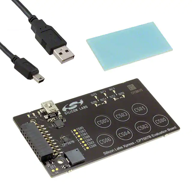
Silicon Labs SLEXP8007A
- Part No.:
- SLEXP8007A
- Manufacturer:
- Silicon Labs
- Category:
- Sensor Evaluation Boards
- Package:
- Datasheet:
-
SLEXP8007A.pdf
- Description:
- CAP SENSE EVAL BOARD
- Quantity:
- Payment:

- Shipping:

Inventory:4,454
Please send an inquiry. Send us your inquiry, and we will respond immediately.
Product details
Overview
SLEXP8007A from Silicon Labs is a Smart Interface Controller IC designed as a USB-to-UART bridge controller with integrated USB 2.0 full-speed transceiver, 3.3 V LDO regulator, and UART supporting up to 3 Mbaud. It operates from a single 5 V USB supply, delivers <195 µA suspend current, and targets embedded diagnostics and industrial connectivity applications.
For engineers reviewing the SLEXP8007A datasheet, SLEXP8007A pinout, SLEXP8007A application, or SLEXP8007A equivalent, key selection criteria include USB CDC compliance, UART baud rate stability across temperature, integrated voltage regulation, and minimal external component count for rapid integration into space-constrained designs.
Technical Context
The SLEXP8007A implements a USB 2.0 full-speed (12 Mbps) device controller compliant with USB CDC ACM class, eliminating need for custom USB firmware. Its UART supports programmable data formats (5–9 bits, 1/2 stop bits, parity), hardware flow control (RTS/CTS), and automatic baud rate detection.
Internally, it integrates a precision 48 MHz USB clock generator, a 3.3 V low-dropout regulator delivering up to 100 mA, and GPIOs configurable as UART control lines or general-purpose I/O. No external crystal or oscillator is required.
Key Specifications
| Parameter | Value and Actual Design Meaning |
|---|---|
| USB Interface | USB 2.0 full-speed (12 Mbps), CDC ACM class-compliant - enables plug-and-play operation on Windows/macOS/Linux without custom driver development |
| UART Max Baud Rate | 3 Mbaud - supports high-throughput serial communication for real-time diagnostics and firmware updates |
| Supply Input | Single 5 V USB bus power - eliminates need for external DC-DC or LDO in most host-powered applications |
| Output Voltage | 3.3 V regulated output, 100 mA max - powers external logic or sensors directly, reducing BOM count |
| USB Suspend Current | 195 µA - meets USB specification for low-power suspend mode, critical for battery-backed or energy-sensitive systems |
| Operating Temperature | –40 °C to +85 °C - qualified for industrial environments including factory automation and smart metering |
| Package | QFN-20 (4 mm × 4 mm, 0.5 mm pitch) - compact footprint compatible with automated SMT assembly and dense PCB layouts |
Pinout & Package
Package: QFN-20, 4 mm × 4 mm, exposed thermal pad, RoHS-compliant.
| Pin/Terminal | Circuit Role | Design Meaning |
|---|---|---|
| VBUS | USB bus voltage sense | Detects presence of 5 V USB power to enable internal regulator and wake from suspend |
| VBUSO | USB overvoltage protection output | Open-drain signal indicating overvoltage condition on VBUS - used for system-level fault reporting |
| REGIN | Regulator input | Input to internal 3.3 V LDO; tied to VBUS when using USB-only power |
| VDD | 3.3 V regulator output | Powers internal logic and external peripherals; decoupling capacitor required |
| TXD | UART transmit output | CMOS-level serial data output driving external MCU or peripheral RX line |
| RXD | UART receive input | CMOS-level serial data input accepting signals from external TX line |
| RTS# | UART request-to-send active-low | Hardware flow control output asserting when RX FIFO nears full - prevents UART overrun |
| CTS# | UART clear-to-send active-low | Hardware flow control input enabling TX only when external device asserts ready state |
| GPIO0–GPIO3 | General-purpose I/O | Configurable as inputs/outputs; support interrupt-on-change and can drive LEDs or status indicators |
| NC | No connect | Not bonded internally; must be left unconnected per datasheet |
Key Features
| Feature | Design Value |
|---|---|
| Integrated USB transceiver and clock | Eliminates external crystal, USB PHY, and clock buffer - reduces bill-of-materials by ≥4 components |
| USB CDC ACM class compliance | Enables native OS driver support on Windows (usbser.sys), macOS (IOUSBFamily), and Linux (cdc_acm) - zero driver porting effort |
| Auto-baud rate detection | Adapts UART timing dynamically to incoming stream - simplifies host-side configuration and improves interoperability |
| Low-power suspend mode | Draws only 195 µA during USB suspend - extends runtime in battery-powered diagnostic tools and portable test equipment |
| GPIO with interrupt capability | Four pins support edge-triggered interrupts - enables wake-from-suspend via external button or sensor event without host polling |
Applications
| Industrial Diagnostic Tool | Smart Meter Communication Module |
|---|---|
Use Scenario: Handheld field tester connecting to legacy RS-232/RS-485 devices via level-shifter and communicating with PC via USB. IC Role / Device Role / Timing Role: USB-to-UART bridge converting USB packets to asynchronous serial frames with precise baud timing and flow control handshake. Use Value: Enables direct USB connection without requiring host-side FTDI or CP210x drivers; 3 Mbaud supports fast firmware uploads and real-time sensor logging. | Use Scenario: Communication interface inside electricity meter for HAN (Home Area Network) data exchange with gateway via isolated UART. IC Role / Device Role / Timing Role: Isolated UART bridge providing galvanically separated USB debug port for firmware updates and calibration data retrieval. Use Value: Integrated 3.3 V regulator powers isolation barrier ICs; low suspend current minimizes impact on meter's battery backup during idle periods. |
| Factory Automation PLC Adapter | Medical Device Serial Debug Port |
Use Scenario: Retrofit adapter board linking legacy PLC serial ports (Modbus RTU) to modern USB-based SCADA systems. IC Role / Device Role / Timing Role: Protocol-transparent UART bridge maintaining Modbus frame integrity and timing margins under variable load. Use Value: Hardware RTS/CTS flow control prevents frame corruption during high-speed polling; –40 °C to +85 °C rating ensures reliability in unconditioned control cabinets. | Use Scenario: Embedded debug interface in portable ultrasound or infusion pump for technician service access and log extraction. IC Role / Device Role / Timing Role: Secure, low-power USB endpoint providing authenticated serial console access during maintenance mode. Use Value: 195 µA suspend current preserves battery life between service intervals; GPIOs signal service mode activation to host MCU via dedicated pin. |
Equivalent & Alternatives
The following parts are listed as comparable options for similar USB-to-UART bridge applications.
| Alternative Part | Technical Difference | Application Difference | Selection Advice |
|---|---|---|---|
| CP2102N-A02-GQFN20 | Same QFN-20 package; supports up to 2 Mbaud (vs. 3 Mbaud); no integrated VBUS overvoltage detection | Lacks VBUSO pin - requires external overvoltage protection circuitry in harsh industrial environments | Preferred where cost sensitivity outweighs need for 3 Mbaud or robust VBUS monitoring |
| FTDI FT231XS-Q | QFN-20, USB 2.0 full-speed, supports 3 Mbaud; requires external 3.3 V supply or separate LDO | No integrated regulator - increases BOM count and layout complexity for single-supply designs | Selected when existing design already provides clean 3.3 V rail and legacy FTDI driver compatibility is mandatory |
Compared with CP2102N-A02-GQFN20 and FT231XS-Q, the SLEXP8007A uniquely combines 3 Mbaud UART, integrated 3.3 V regulator, and VBUS overvoltage monitoring in one QFN-20 package - reducing external components and improving system-level fault resilience without sacrificing performance.
Availability
SLEXP8007A is available at Aetrix Electronics and suitable for industrial diagnostic tools, smart meter communication modules, factory automation PLC adapters, and medical device debug interfaces requiring stable component supply, long-term lifecycle assurance, and consistent parametric performance.
Supply support for SLEXP8007A includes scheduled delivery planning, volume procurement assistance, BOM continuity management, traceable sourcing, and lifecycle availability coordination for OEM customers, industrial embedded developers, connected-device designers, and electronics production programs.
Manufacturer
Silicon Labs is a fabless semiconductor company specializing in secure, intelligent wireless and wired connectivity solutions for IoT, industrial, and consumer markets.
The SLEXP8007A belongs to Silicon Labs' Smart Interface Controller IC family, engineered specifically to simplify USB integration in resource-constrained embedded systems while maintaining industrial-grade reliability and regulatory compliance.
FAQ
Does the SLEXP8007A require an external crystal or oscillator?
No, the SLEXP8007A integrates a precision 48 MHz USB clock generator and does not require any external crystal, oscillator, or clock source. This eliminates two passive components and associated layout constraints, simplifying design and improving time-to-market. The internal clock meets USB full-speed timing accuracy requirements across temperature and voltage ranges, and is used for both USB packet timing and UART baud generation in the SLEXP8007A.
What operating systems support the SLEXP8007A out of the box?
The SLEXP8007A is USB CDC ACM class-compliant and works natively with standard OS drivers: Windows (usbser.sys), macOS (IOUSBFamily), and Linux (cdc_acm). No custom driver installation is needed. This plug-and-play behavior is verified across Windows 10/11, macOS 12–14, and Linux kernels ≥4.15. The SLEXP8007A enumerates as a standard COM port, enabling immediate use with terminal emulators, scripting tools, and firmware update utilities.
Can the SLEXP8007A power external circuitry?
Yes, the SLEXP8007A provides a regulated 3.3 V output (VDD pin) capable of delivering up to 100 mA. This output powers the internal logic and can also supply external components such as level shifters, optocouplers, or low-power sensors. A minimum 1 µF ceramic decoupling capacitor is required at the VDD pin. When used in this way, the SLEXP8007A reduces the need for a separate LDO, lowering total system cost and board area.
How does the SLEXP8007A handle UART flow control?
The SLEXP8007A supports full hardware flow control using RTS# (output) and CTS# (input) pins. RTS# asserts low when the internal RX FIFO reaches 75% capacity, signaling the external UART to pause transmission. CTS# must be driven low by the external device to enable SLEXP8007A TX. This prevents data loss during burst transfers and is fully implemented in hardware - no firmware intervention required. Flow control remains active across all supported baud rates, including 3 Mbaud.
Is the SLEXP8007A suitable for extended temperature applications?
Yes, the SLEXP8007A is rated for operation from –40 °C to +85 °C and qualified per industrial-grade reliability standards. It maintains full USB functionality, UART timing accuracy, and regulator output stability across this range. Thermal performance has been validated in sealed enclosures with no forced airflow, making it appropriate for deployment in outdoor smart meters, factory-floor PLCs, and HVAC controllers where ambient temperatures exceed commercial limits.
SLEXP8007A Specifications
- Product attributes
- Attribute value
- Manufacturer:
- Silicon Labs
- Series:
- -
- Packaging:
- Bulk
- Product Status:
- Obsolete
- Sensor Type:
- Touch, Capacitive
- Sensing Range:
- 7 Buttons/Keys
- Interface:
- USB
- Sensitivity:
- -
- Voltage - Supply:
- -
- Embedded:
- -
- Contents:
- Board(s), Cable(s)
- Utilized IC / Part:
- CPT007B
SLEXP8007A FAQ
1.How can I place an order for SLEXP8007A through Aetrix?
Please submit a Request for Quotation (RFQ) for SLEXP8007A on Aetrix. Our sales agent will provide a competitive quotation and guide you through the order confirmation once you accept the terms.
2.Are the price and stock information for SLEXP8007A reliable?
The price and inventory of SLEXP8007A are updated periodically and may fluctuate due to market conditions. Stock and pricing data are typically refreshed every 24 hours. Quotation validity for SLEXP8007A is usually 5 days.
3.What payment methods are accepted for SLEXP8007A?
We accept Wire Transfer, PayPal, Credit Card, Western Union, MoneyGram, and Escrow for SLEXP8007A transactions.
Note: Certain payment methods may incur a processing fee.
4.How is shipping managed for SLEXP8007A?
SLEXP8007A orders can be shipped via leading logistics carriers, including DHL, UPS, FedEx, TNT, or Registered Mail.
Once your SLEXP8007A order is processed, you will receive an email with the shipment details and tracking number.
Note: Tracking information may take up to 24 hours to appear. Express delivery typically takes 3–5 business days.
5.How can I obtain technical support or documentation for SLEXP8007A?
For technical support, including SLEXP8007A datasheets, pinout diagrams, or application guidance, please contact our engineering support team. They can provide detailed documentation and assistance for your SLEXP8007A requirements.
6.How does Aetrix verify that SLEXP8007A is sourced from the original manufacturer or authorized distributors?
All SLEXP8007A products on Aetrix are procured from qualified distributors and authorized channels. Our dedicated quality assurance team conducts strict verification, including traceability checks and, if necessary, third-party testing. This ensures that SLEXP8007A meets industry standards.
7.What is the process for return or replacement of SLEXP8007A?
All SLEXP8007A units undergo pre-shipment inspection (PSI). If there is an issue with SLEXP8007A, returns or replacements are accepted under the following conditions:
1.Quantity discrepancies, incorrect items, or visible external defects (such as breakage or corrosion), acknowledged by Aetrix.
2.The issue is reported within 90 days of delivery.
3.The SLEXP8007A part is unused and in its original packaging.
Return procedure for SLEXP8007A:
1.Submit a request within 90 days.
2.Obtain a Return Material Authorization (RMA) from Aetrix.
SLEXP8007A Tags
-
1782
Adafruit Industries LLC
-
SEN0142
DFRobot

-
2857
Adafruit Industries LLC
-
3316
Adafruit Industries LLC
-
2652
Adafruit Industries LLC
-
3317
Adafruit Industries LLC
-
163
Adafruit Industries LLC
-
SEN-09269
SparkFun Electronics
-
3709
Adafruit Industries LLC
-
1018
Adafruit Industries LLC
-
VL53L5CX-SATEL
STMicroelectronics
-
3387
Adafruit Industries LLC
Tech Hub

Comparator circuit design covering voltage thresholds, input limits, open-collector outputs, LM393 wiring, op-amp differences, hysteresis, timing, window detection and practical fault diagnosis.
Schmitt triggers use separate rising and falling thresholds to stabilize slow or noisy signals. This guide covers hysteresis, 74HC14 and 74HCT14 selection, comparator calculations, RC oscillators and p…
Counterfeit components can hide behind convincing markings and passing basic function tests. This engineering reference covers source traceability, external inspection, X-ray, XRF, electrical testing, …
A practical engineering and sourcing framework covering lifecycle verification, lifetime-buy calculations, replacement qualification, supplier checks and counterfeit-risk controls.
TTL and CMOS logic families differ in thresholds, loading, output drive, power and timing. This engineering guide compares 74HC and 74HCT, calculates noise margins and checks 3.3 V/5 V compatibility.
A practical engineering guide to 3.3V and 5V logic compatibility, input thresholds, resistor dividers, translator ICs, MOSFET level shifting, I2C pull-ups, timing limits and power-sequencing risks.
The 74HC595 uses push-pull logic outputs, while the TPIC6B595 uses 50 V open-drain DMOS sinks for higher-power loads. This guide compares timing, current limits, 3.3 V interfacing, load wiring, thermal…
The 74HC595 converts serial data into eight stable parallel outputs. This guide covers pin functions, shift and storage timing, OE and MR behavior, drive-current limits, cascading, voltage compatibilit…
A technical comparison of level-sensitive latches and edge-triggered flip-flops, covering timing windows, setup and hold limits, master–slave operation, time borrowing, race-through, HDL inference and…
A D latch stores one bit while Enable controls when data can pass. This reference covers gate-level operation, truth tables, transparency, setup and hold timing, LE versus OE, common ICs and practical …