Vishay Semiconductor Opto Division TEMT1030
- Part No.:
- TEMT1030
- Manufacturer:
- Vishay Semiconductor Opto Division
- Category:
- Phototransistors
- Package:
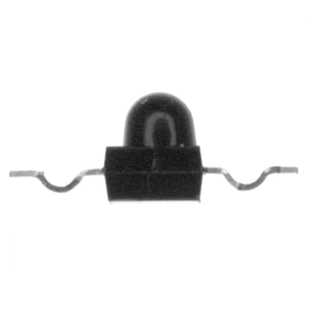
- 2-SMD, Yoke Bend
- Datasheet:
-
TEMT1030.pdf
- Description:
- PHOTOTRANSISTOR 730 TO 1000 NM
- Quantity:
- Payment:

- Shipping:

Inventory:561
Please send an inquiry. Send us your inquiry, and we will respond immediately.
Product details
Overview
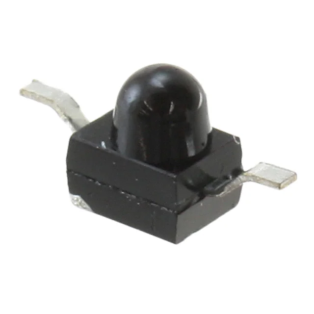
TEMT1030 from Vishay Semiconductors is a silicon NPN phototransistor in a surface-mount yoke package with daylight-blocking filter, 7 mA collector light current (Ica) at 1 mW/cm² irradiance, ±15° angle of half sensitivity, and peak spectral response at 880 nm. It is used in IR-based photo interrupters and encoder detection where ambient-light rejection and fast 2.0 μs turn-on time are required.
For engineers reviewing the TEMT1030 datasheet, TEMT1030 pinout, TEMT1030 application, or TEMT1030 equivalent, this page delivers verified package dimensions (7.9 × 5 × 2.7 mm), absolute maximum ratings (VECO = 5 V, IC = 50 mA), spectral bandwidth (730–1000 nm), thermal resistance (RthJA = 400 K/W), and reflow compatibility per J-STD-020 MSL 3.
Technical Context
The TEMT1030 operates as a light-controlled NPN transistor with emitter-collector voltage rating of 5 V and collector dark current ≤200 nA at VCE = 20 V. Its daylight-blocking filter ensures high signal-to-noise ratio when paired with 870–950 nm IR emitters like TSML1000 series.
It features fast switching (ton = 2.0 μs, toff = 2.3 μs at IC = 5 mA, RL = 100 Ω) and low capacitance (CCEO = 3 pF typical at VCE = 5 V, f = 1 MHz), enabling reliable performance in high-speed opto-isolated feedback and position-sensing circuits.
Key Specifications
| Parameter | Value and Actual Design Meaning |
|---|---|
| VECO | 5 V - Maximum reverse-biased emitter-collector voltage before breakdown; defines safe operating range in reverse-active configuration. |
| Ica | 7 mA typical at Ee = 1 mW/cm², λ = 950 nm - Output current level under standard IR illumination; sets load resistor sizing for digital logic interfacing. |
| ϕ | ±15° - Angular field over which sensitivity drops to 50%; enables precise alignment tolerance in mechanical encoder slots. |
| ton/toff | 2.0 / 2.3 μs - Switching speed at IC = 5 mA, RL = 100 Ω; supports >100 kHz pulse detection in counting and timing applications. |
| λ0.5 | 730–1000 nm - Full spectral bandwidth at 50% relative sensitivity; confirms compatibility with common 850/940 nm IR LEDs. |
| RthJA | 400 K/W - Thermal resistance junction-to-ambient on 4 mm × 4 mm PCB pad; informs derating above 55 °C ambient. |
| VCEsat | ≤0.3 V at IC = 0.1 mA - Saturation voltage under light drive; ensures low-voltage drop for direct TTL/CMOS input interfacing. |
Pinout & Package
TEMT1030 uses a 3-terminal yoke-style surface-mount package (Drawing-No.: 6.544-5329.02-4, Issue: 4) with overall dimensions 7.9 × 5.0 × 2.7 mm. Terminals are arranged with Collector (C) and Emitter (E) on opposing sides of the molded body; no base connection is externally accessible.
| Pin/Terminal | Circuit Role | Design Meaning |
|---|---|---|
| Collector (C) | Anode-side output terminal | Connected to VCC via load resistor; sinks photocurrent when illuminated; polarity matches NPN phototransistor operation. |
| Emitter (E) | Cathode-side reference terminal | Typically grounded; establishes return path for photocurrent; voltage at C relative to E determines output logic level. |
| Case / Molded Body | Optical lens housing | Integrates daylight-blocking filter and ±15° angular collimation; lens geometry optimized for coupling with TSML1000-series IR emitters. |
Key Features
| Feature | Design Value |
|---|---|
| Daylight-blocking filter | Matches 870–950 nm IR emitters; rejects visible spectrum to prevent false triggering in ambient-light environments. |
| Yoke package form | Enables robust mechanical mounting in photo interrupter housings; provides stable optical axis alignment without solder joint stress. |
| MSL 3 moisture sensitivity | 168-hour floor life per J-STD-020; requires bake or dry-box storage after tape opening to prevent popcorning during reflow. |
| Fast response time | 2.0 μs turn-on enables real-time detection of high-frequency IR pulses in rotary encoders and object counters. |
| Spectral peak at 880 nm | Aligns with high-efficiency GaAlAs IR LED output; maximizes signal amplitude while minimizing power consumption. |
Applications
| Photo Interrupter Detection | Rotary Encoder Position Sensing |
|---|---|
|
Use Scenario: Detecting opaque objects passing between IR emitter and detector in vending machines or printer paper-path sensors. IC Role / Device Role / Timing Role: Light-controlled switch providing open-collector digital output synchronized to mechanical motion. Use Value: ±15° angular tolerance and 2.0 μs response enable reliable edge detection at speeds up to 50,000 rpm in compact interrupter gaps. |
Use Scenario: Reading slotted or perforated disks in motor feedback systems for speed and direction measurement. IC Role / Device Role / Timing Role: Optical sensor generating quadrature-compatible pulse trains via dual-channel placement. Use Value: 730–1000 nm spectral bandwidth ensures consistent output across temperature drift of IR emitters, maintaining count accuracy. |
| Industrial Counter Systems | IR-Based Proximity Switch |
|
Use Scenario: Counting bottles on conveyor belts using reflected or transmitted IR beams in packaging lines. IC Role / Device Role / Timing Role: High-sensitivity photodetector converting beam interruption into clean TTL-level pulses. Use Value: 7 mA Ica and ≤0.3 V VCEsat allow direct interface with microcontroller GPIOs without external amplification. |
Use Scenario: Non-contact presence detection of metal or plastic parts near machinery guards or assembly stations. IC Role / Device Role / Timing Role: Ambient-light-immune proximity sensor operating in unshielded factory lighting conditions. Use Value: Daylight-blocking filter and <200 nA dark current ensure stable high/low state discrimination without software debouncing. |
Equivalent & Alternatives
The following parts are listed as comparable options for similar phototransistor applications.
| Alternative Part | Technical Difference | Application Difference | Selection Advice |
|---|---|---|---|
| TEMT1020 | Gullwing package (vs. yoke); identical electrical specs (Ica, ϕ, λp, ton) and optical filter. | Requires different PCB footprint and stencil design; better suited for automated placement on dense boards. | Select TEMT1020 only if gullwing mountability and 2.3 × 1.1 mm lead pitch are preferred over yoke mechanical stability. |
| TEMT1000 | Reverse gullwing package; same optical and electrical parameters; differs only in leadform orientation and solder pad layout. | Not interchangeable without PCB redesign; intended for mirrored board layouts requiring reversed terminal polarity. | Choose TEMT1000 only when reverse gullwing mechanical fit or specific thermal pad routing is required. |
Compared with TEMT1030, TEMT1020 offers identical photometric performance in a gullwing package for higher-density SMT assembly, while TEMT1000 provides the same sensitivity in a reverse-gullwing variant-neither is pin-compatible, and all three require unique land patterns despite shared core functionality.
Availability
TEMT1030 is available at Aetrix Electronics and suitable for photo interrupters, rotary encoders, industrial counters, and IR proximity switches requiring stable component supply, RoHS-compliant packaging, and MSL 3 handling support.
Supply support for TEMT1030 includes scheduled delivery planning, volume procurement assistance, BOM continuity management, traceable sourcing, and lifecycle availability coordination for OEM customers, industrial embedded developers, connected-device designers, and electronics production programs.
Manufacturer
Vishay Semiconductors is a global leader in discrete semiconductors and passive components, specializing in high-reliability optoelectronics, power MOSFETs, and precision resistors.
The TEMT1000 series-including TEMT1030-is designed for industrial and consumer IR detection applications demanding ambient-light immunity, fast response, and surface-mount mechanical robustness.
FAQ
What is the maximum collector-emitter voltage rating for TEMT1030?
The TEMT1030 has an absolute maximum emitter-collector voltage (VECO) of 5 V. This rating applies under reverse-biased conditions and must not be exceeded to avoid junction breakdown. The device is rated for 70 V VCEO in forward-active mode, but its primary use case leverages the 5 V VECO limit for optical switch configurations. Always observe this 5 V limit in emitter-follower or reverse-connected topologies.
Does TEMT1030 have a base connection for external bias control?
No, TEMT1030 is a two-terminal phototransistor with only Collector and Emitter leads exposed. It lacks an accessible base terminal, operating solely on photogenerated base current. This simplifies circuit design by eliminating external bias networks but means gain and response cannot be adjusted via base voltage-the device relies entirely on incident irradiance and load resistor selection for output behavior.
What is the spectral response range of TEMT1030, and how does it match common IR emitters?
TEMT1030 exhibits a spectral bandwidth (λ0.5) from 730 nm to 1000 nm, with peak sensitivity at 880 nm. This range aligns precisely with standard 850 nm and 940 nm GaAlAs IR emitters, including Vishay's TSML1000 series. The daylight-blocking filter suppresses visible light, ensuring high signal fidelity even in brightly lit industrial environments where ambient IR noise would otherwise degrade detection reliability.
Can TEMT1030 be used in reflow soldering processes, and what MSL level does it comply with?
Yes, TEMT1030 is qualified for lead-free reflow per J-STD-020 and carries Moisture Sensitivity Level (MSL) 3, with a floor life of 168 hours at ≤30 °C/60% RH. After tape opening, it must be assembled within one week or stored in a dry box with desiccant. Reflow peak temperature must not exceed 260 °C for ≤10 s, and preheat must follow the specified 1°C/s to 5°C/s ramp rate to prevent package damage or delamination.
How does the yoke package of TEMT1030 differ mechanically from TEMT1020 or TEMT1000?
The TEMT1030 uses a yoke-style surface-mount package (7.9 × 5.0 × 2.7 mm) with terminals extending laterally from opposite sides of the molded body-distinct from TEMT1020's gullwing leads (2.3 × 1.1 mm pitch) and TEMT1000's reverse gullwing form. The yoke design provides superior mechanical rigidity for photo interrupter assemblies, resists bending during insertion, and maintains fixed optical axis alignment without reliance on solder joint integrity.
TEMT1030 Specifications
- Product attributes
- Attribute value
- Manufacturer:
- Vishay Semiconductor Opto Division
- Series:
- -
- Package/Case:
- 2-SMD, Yoke Bend
- Packaging:
- Tape & Reel (TR)
- Product Status:
- Active
- Voltage - Collector Emitter Breakdown (Max):
- 70 V
- Current - Collector (Ic) (Max):
- 50 mA
- Current - Dark (Id) (Max):
- 200 nA
- Wavelength:
- 950nm
- Viewing Angle:
- 30°
- Power - Max:
- 100 mW
- Mounting Type:
- Surface Mount
- Orientation:
- Top View
- Operating Temperature:
- -40°C ~ 85°C
- Grade:
- -
- Qualification:
- -
TEMT1030 FAQ
1.How can I place an order for TEMT1030 through Aetrix?
Please submit a Request for Quotation (RFQ) for TEMT1030 on Aetrix. Our sales agent will provide a competitive quotation and guide you through the order confirmation once you accept the terms.
2.Are the price and stock information for TEMT1030 reliable?
The price and inventory of TEMT1030 are updated periodically and may fluctuate due to market conditions. Stock and pricing data are typically refreshed every 24 hours. Quotation validity for TEMT1030 is usually 5 days.
3.What payment methods are accepted for TEMT1030?
We accept Wire Transfer, PayPal, Credit Card, Western Union, MoneyGram, and Escrow for TEMT1030 transactions.
Note: Certain payment methods may incur a processing fee.
4.How is shipping managed for TEMT1030?
TEMT1030 orders can be shipped via leading logistics carriers, including DHL, UPS, FedEx, TNT, or Registered Mail.
Once your TEMT1030 order is processed, you will receive an email with the shipment details and tracking number.
Note: Tracking information may take up to 24 hours to appear. Express delivery typically takes 3–5 business days.
5.How can I obtain technical support or documentation for TEMT1030?
For technical support, including TEMT1030 datasheets, pinout diagrams, or application guidance, please contact our engineering support team. They can provide detailed documentation and assistance for your TEMT1030 requirements.
6.How does Aetrix verify that TEMT1030 is sourced from the original manufacturer or authorized distributors?
All TEMT1030 products on Aetrix are procured from qualified distributors and authorized channels. Our dedicated quality assurance team conducts strict verification, including traceability checks and, if necessary, third-party testing. This ensures that TEMT1030 meets industry standards.
7.What is the process for return or replacement of TEMT1030?
All TEMT1030 units undergo pre-shipment inspection (PSI). If there is an issue with TEMT1030, returns or replacements are accepted under the following conditions:
1.Quantity discrepancies, incorrect items, or visible external defects (such as breakage or corrosion), acknowledged by Aetrix.
2.The issue is reported within 90 days of delivery.
3.The TEMT1030 part is unused and in its original packaging.
Return procedure for TEMT1030:
1.Submit a request within 90 days.
2.Obtain a Return Material Authorization (RMA) from Aetrix.
TEMT1030 Tags
-
ALS-PT19-315C/L177/TR8
Everlight Electronics Co Ltd
-
PT19-21C/L41/TR8
Everlight Electronics Co Ltd
-
PT12-21C/TR8
Everlight Electronics Co Ltd
-
PT12-21B/TR8
Everlight Electronics Co Ltd

-
ALS-PT204-6C/L177
Everlight Electronics Co Ltd
.jpg)
-
APA3010P3BT-GX
Kingbright

-
PT26-51B/TR8(DGK)
Everlight Electronics Co Ltd
-
OP550A
TT Electronics/Optek Technology
-
OP505A
TT Electronics/Optek Technology
-
OP598A
TT Electronics/Optek Technology

-
PT42-21B/TR8
Everlight Electronics Co Ltd
-
QSB363ZR
onsemi
Tech Hub

Comparator circuit design covering voltage thresholds, input limits, open-collector outputs, LM393 wiring, op-amp differences, hysteresis, timing, window detection and practical fault diagnosis.
Schmitt triggers use separate rising and falling thresholds to stabilize slow or noisy signals. This guide covers hysteresis, 74HC14 and 74HCT14 selection, comparator calculations, RC oscillators and p…
Counterfeit components can hide behind convincing markings and passing basic function tests. This engineering reference covers source traceability, external inspection, X-ray, XRF, electrical testing, …
A practical engineering and sourcing framework covering lifecycle verification, lifetime-buy calculations, replacement qualification, supplier checks and counterfeit-risk controls.
TTL and CMOS logic families differ in thresholds, loading, output drive, power and timing. This engineering guide compares 74HC and 74HCT, calculates noise margins and checks 3.3 V/5 V compatibility.
A practical engineering guide to 3.3V and 5V logic compatibility, input thresholds, resistor dividers, translator ICs, MOSFET level shifting, I2C pull-ups, timing limits and power-sequencing risks.
The 74HC595 uses push-pull logic outputs, while the TPIC6B595 uses 50 V open-drain DMOS sinks for higher-power loads. This guide compares timing, current limits, 3.3 V interfacing, load wiring, thermal…
The 74HC595 converts serial data into eight stable parallel outputs. This guide covers pin functions, shift and storage timing, OE and MR behavior, drive-current limits, cascading, voltage compatibilit…
A technical comparison of level-sensitive latches and edge-triggered flip-flops, covering timing windows, setup and hold limits, master–slave operation, time borrowing, race-through, HDL inference and…
A D latch stores one bit while Enable controls when data can pass. This reference covers gate-level operation, truth tables, transparency, setup and hold timing, LE versus OE, common ICs and practical …









