Qorvo TGL4203-SM
- Part No.:
- TGL4203-SM
- Manufacturer:
- Qorvo
- Category:
- Attenuators
- Package:
- 16-VFQFN Exposed Pad
- Datasheet:
-
TGL4203-SM.pdf
- Description:
- DC-30 GHZ WB ANALOG ATTN
- Quantity:
- Payment:

- Shipping:

Inventory:300
Please send an inquiry. Send us your inquiry, and we will respond immediately.
Product details
Overview
TGL4203-SM from Qorvo (formerly TriQuint) is a DC–30 GHz wideband analog voltage-controlled attenuator in a 3×3 mm 16-lead QFN package, delivering 17 dB attenuation range, 1.5 dB typical insertion loss, >20 dBm input P1dB at 10 dB attenuation, and -40 dBc IM3 at 6 dBm tone power-designed for RF front-end signal level control in point-to-point radio transceivers.
For engineers reviewing the TGL4203-SM datasheet, pinout, applications, or equivalent options, key selection criteria include its GaAs pHEMT-based broadband flatness (±0.5 dB IL ripple), bias-controlled attenuation linearity across 30 GHz, thermal stability (-0.01 dB/°C IL drift), and compatibility with high-reliability military/space RF subsystems requiring RoHS-compliant surface-mount integration.
Technical Context
The TGL4203-SM employs a monolithic GaAs 0.25 µm mmw pHEMT process to achieve continuous DC–30 GHz operation with two independent analog bias inputs (V1, V2) enabling precise attenuation tuning. Its architecture supports bidirectional RF flow (RF In/Out reversible) and integrates on-chip matching for 50 Ω systems without external components.
Thermal design centers on low junction-to-case resistance (θjc = 42 °C/W) and channel temperature derating guidance up to 200 °C, supporting sustained operation under +24 dBm CW input at baseplate temperatures ≤70 °C. Bias optimization targets attenuation flatness and group delay variation (<±5 ps) over full bandwidth.
Key Specifications
| Parameter | Value and Actual Design Meaning |
|---|---|
| Frequency Range | DC to 30 GHz - enables single-component coverage of microwave bands from L-band through Ka-band without band switching. |
| Attenuation Range | 17 dB typical (13–19 dB min–max) - provides sufficient dynamic range for AGC loops and transmitter output leveling. |
| Insertion Loss | 1.5 dB typical (≤3 dB max up to 20 GHz) - minimizes signal path degradation while maintaining broadband impedance match. |
| Input P1dB | >20 dBm @ 10 dB attenuation - ensures linear operation with high-power RF signals common in point-to-point radios. |
| IM3 Distortion | -40 dBc @ Pin/Tone = 6 dBm - meets spectral purity requirements for multi-carrier and OFDM systems. |
| Bias Range | V1/V2 = -1 V to 0 V (recommended); -5 V to +1 V (absolute max) - allows fine-grained analog control using standard DAC outputs. |
| Package | 3 × 3 × 0.9 mm 16-lead QFN - supports high-density RF PCB layouts with exposed thermal pad for efficient heat dissipation. |
Pinout & Package
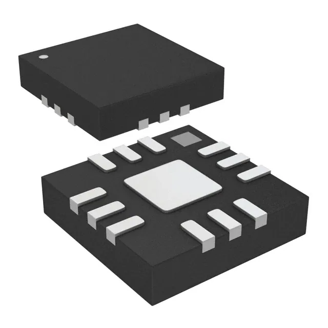
Package: 3×3 mm QFN with exposed thermal pad, 16 leads, lead-free and RoHS compliant. Pin 1 marked by dot; pins 1,2,4,9,11,12 are ground connections; pins 3 and 10 serve as RF input and output (reversible); pins 6 and 7 are V1 and V2 control terminals; pins 5,8,13,14,15,16 are no-connect.
| Pin/Terminal | Circuit Role | Design Meaning |
|---|---|---|
| 1, 2, 4, 9, 11, 12 | GND | RF and DC return paths; must be low-inductance connected to solid ground plane for broadband stability. |
| 3 | RF In | Primary RF input port; bidirectional capability allows use as RF Out if layout requires. |
| 6 | V1 | Analog attenuation control voltage input; bias range -1 V to 0 V sets coarse attenuation step. |
| 7 | V2 | Analog attenuation control voltage input; bias range -1 V to 0 V sets fine attenuation adjustment. |
| 10 | RF Out | Primary RF output port; matched to 50 Ω; reverse usage supported per datasheet. |
| 5, 8, 13, 14, 15, 16 | N/C | No internal connection; must remain unconnected and unstubbed to avoid parasitic resonance. |
Key Features
| Feature | Design Value |
|---|---|
| DC–30 GHz Operation | Single-component broadband coverage eliminates need for multiple narrowband attenuators or switches in multi-band radios. |
| 17 dB Attenuation Range | Enables robust automatic gain control (AGC) across varying link budgets without digital calibration overhead. |
| ±0.5 dB Insertion Loss Ripple | Ensures consistent amplitude response across full frequency band-critical for wideband modulation fidelity. |
| -0.01 dB/°C IL Temperature Coefficient | Minimizes gain drift over operating temperature range, reducing need for closed-loop compensation in outdoor equipment. |
| Reversible RF Ports | Allows flexible PCB routing and reuse in both transmit and receive signal chains without redesign. |
Applications
| Point-to-Point Radio Transceivers | Fiber Optic Transmitter Drivers |
|---|---|
Use Scenario: High-capacity licensed microwave links operating from 6 to 30 GHz requiring stable output power control across temperature and aging. IC Role / Device Role / Timing Role: Analog voltage-controlled RF attenuator in transmitter output stage for precise EIRP management and spectrum mask compliance. Use Value: Delivers 17 dB dynamic range with <±0.5 dB ripple and -40 dBc IM3 to maintain ACLR and adjacent-channel interference below regulatory limits. | Use Scenario: High-speed optical modules (e.g., 100G/400G coherent transceivers) where RF driver amplifiers require pre-distortion-compensated signal conditioning. IC Role / Device Role / Timing Role: Wideband analog attenuator placed between DAC output and driver amplifier to normalize signal envelope prior to optical modulation. Use Value: DC–30 GHz bandwidth and flat group delay (<±5 ps) preserve signal integrity for multi-Gbaud NRZ/PAM4 waveforms without phase distortion. |
| Military Radar Front-Ends | Test & Measurement Instrumentation |
Use Scenario: Active electronically scanned array (AESA) radar receivers needing calibrated RF path loss adjustment across wide instantaneous bandwidths. IC Role / Device Role / Timing Role: Digitally controlled analog attenuator in receiver channel for real-time gain balancing and dynamic range optimization. Use Value: >20 dBm P1dB and 15 dB return loss ensure minimal compression and reflection-induced measurement error during pulsed RF operation. | Use Scenario: Vector network analyzers and signal generators requiring broadband, repeatable attenuation standards traceable to calibration labs. IC Role / Device Role / Timing Role: Reference-grade analog attenuator used in internal calibration paths and output leveling circuits. Use Value: Stable 1.5 dB insertion loss and ±0.01 dB/°C temperature coefficient enable sub-0.1 dB absolute accuracy over lab temperature ranges. |
Equivalent & Alternatives
The following parts are listed as comparable options for similar wideband analog attenuator applications.
| Alternative Part | Technical Difference | Application Difference | Selection Advice |
|---|---|---|---|
| HMC650LP3E | DC–20 GHz range; 20 dB attenuation range; requires dual positive supply (+5 V); higher IL (2.5 dB typ) | Limited to K-band and below; less suitable for Ka-band point-to-point or radar front-ends | Select when lower-frequency operation and positive-only bias simplify system power architecture |
| QPA9801 | DC–30 GHz; integrated digital SPI interface; 15 dB attenuation range; 2.0 dB IL; requires external decoupling | Offers programmable control but adds MCU dependency; slightly reduced dynamic range vs. analog biasing | Select when digital control, calibration storage, or remote configuration outweighs analog simplicity |
Compared with HMC650LP3E and QPA9801, the TGL4203-SM delivers superior Ka-band coverage, lowest insertion loss, and pure analog biasing-making it optimal for high-frequency, low-latency, and thermally constrained RF systems where deterministic analog control is preferred over digital overhead.
Availability
TGL4203-SM is available at Aetrix Electronics and suitable for point-to-point radio transceivers, fiber optic transmitter drivers, and military radar front-ends requiring stable component supply, long-term lifecycle support, and RoHS-compliant surface-mount integration.
Supply support for TGL4203-SM includes scheduled delivery planning, volume procurement assistance, BOM continuity management, traceable sourcing, and lifecycle availability coordination for OEM customers, industrial embedded developers, connected-device designers, and electronics production programs.
Manufacturer
Qorvo is a global leader in RF solutions, formed from the merger of TriQuint and RFMD, specializing in high-performance GaAs, GaN, and BAW technologies for defense, infrastructure, and mobile applications.
The TGL4203-SM belongs to Qorvo's millimeter-wave MMIC attenuator product line, engineered specifically for broadband RF signal conditioning in mission-critical wireless infrastructure and aerospace systems demanding DC–30 GHz performance and high reliability.
FAQ
What is the recommended bias voltage range for optimal performance of the TGL4203-SM?
The TGL4203-SM achieves best attenuation flatness and linearity with V1 and V2 set between -1 V and 0 V. Absolute maximum ratings allow -5 V to +1 V, but operation outside the recommended range increases distortion and degrades return loss. The datasheet specifies that bias voltages in this range optimize group delay variation (<±5 ps) and insertion loss ripple (≤0.5 dB) across DC–30 GHz. Always apply bias before RF input to prevent damage.
Can the RF input and output ports of the TGL4203-SM be interchanged in the circuit layout?
Yes, the TGL4203-SM supports bidirectional RF operation: pin 3 (RF In) and pin 10 (RF Out) may be swapped without performance penalty. This flexibility simplifies PCB routing in compact transceiver modules and enables reuse in both transmit and receive signal chains. Measured S-parameters confirm symmetrical return loss (>15 dB) and insertion loss (1.5 dB typ) regardless of direction, provided proper grounding and decoupling are maintained.
What is the thermal resistance and maximum channel temperature specification for the TGL4203-SM?
The TGL4203-SM has a junction-to-case thermal resistance (θjc) of 42 °C/W under 100 mW input power at 70 °C baseplate temperature. Its absolute maximum channel temperature is 200 °C, but for 1E+6 hour median lifetime, channel temperature must be limited to ≤150 °C-requiring input power derating per the formula Pin = (150 °C – Tbase)/θjc. Thermal pad soldering to a solid copper plane is mandatory for reliable operation.
Does the TGL4203-SM require external DC blocking or matching components?
No, the TGL4203-SM is internally matched to 50 Ω across DC–30 GHz and features integrated DC blocking on RF ports. External components are only required for bias decoupling: 1 nF capacitors (0402 size) are recommended on V1 and V2 lines per the evaluation board design. No series inductors, shunt capacitors, or microstrip stubs are needed for basic operation-reducing bill-of-materials and layout complexity.
Is the TGL4203-SM compatible with lead-free reflow assembly processes?
Yes, the TGL4203-SM is RoHS compliant and qualified for lead-free reflow with a peak temperature of 260 °C for ≤20 seconds within 5 °C of the peak. Qorvo recommends a ramp-up rate of 3 °C/sec, activation at 150–200 °C for 60–180 sec, and time above liquidus of 60–150 sec. Conductive solder paste and stencil-printed deposition are advised; hand soldering is not recommended due to thermal sensitivity of the GaAs die and QFN thermal pad.
TGL4203-SM Specifications
- Product attributes
- Attribute value
- Manufacturer:
- Qorvo
- Package/Case:
- 16-VFQFN Exposed Pad
- Series:
- -
- Packaging:
- Tape & Reel (TR)
- Product Status:
- Active
- Attenuation Value:
- 0dB
- Frequency Range:
- 0 Hz ~ 30 GHz
- Power (Watts):
- -
- Impedance:
- -
- Grade:
- -
- Qualification:
- -
TGL4203-SM FAQ
1.How can I place an order for TGL4203-SM through Aetrix?
Please submit a Request for Quotation (RFQ) for TGL4203-SM on Aetrix. Our sales agent will provide a competitive quotation and guide you through the order confirmation once you accept the terms.
2.Are the price and stock information for TGL4203-SM reliable?
The price and inventory of TGL4203-SM are updated periodically and may fluctuate due to market conditions. Stock and pricing data are typically refreshed every 24 hours. Quotation validity for TGL4203-SM is usually 5 days.
3.What payment methods are accepted for TGL4203-SM?
We accept Wire Transfer, PayPal, Credit Card, Western Union, MoneyGram, and Escrow for TGL4203-SM transactions.
Note: Certain payment methods may incur a processing fee.
4.How is shipping managed for TGL4203-SM?
TGL4203-SM orders can be shipped via leading logistics carriers, including DHL, UPS, FedEx, TNT, or Registered Mail.
Once your TGL4203-SM order is processed, you will receive an email with the shipment details and tracking number.
Note: Tracking information may take up to 24 hours to appear. Express delivery typically takes 3–5 business days.
5.How can I obtain technical support or documentation for TGL4203-SM?
For technical support, including TGL4203-SM datasheets, pinout diagrams, or application guidance, please contact our engineering support team. They can provide detailed documentation and assistance for your TGL4203-SM requirements.
6.How does Aetrix verify that TGL4203-SM is sourced from the original manufacturer or authorized distributors?
All TGL4203-SM products on Aetrix are procured from qualified distributors and authorized channels. Our dedicated quality assurance team conducts strict verification, including traceability checks and, if necessary, third-party testing. This ensures that TGL4203-SM meets industry standards.
7.What is the process for return or replacement of TGL4203-SM?
All TGL4203-SM units undergo pre-shipment inspection (PSI). If there is an issue with TGL4203-SM, returns or replacements are accepted under the following conditions:
1.Quantity discrepancies, incorrect items, or visible external defects (such as breakage or corrosion), acknowledged by Aetrix.
2.The issue is reported within 90 days of delivery.
3.The TGL4203-SM part is unused and in its original packaging.
Return procedure for TGL4203-SM:
1.Submit a request within 90 days.
2.Obtain a Return Material Authorization (RMA) from Aetrix.
TGL4203-SM Tags

-
PAT0510S-C-3DB-T10
Susumu

-
PAT0510S-C-10DB-T10
Susumu

-
PAT0510S-C-2DB-T10
Susumu
-
PAT1220-C-10DB-T5
Susumu

-
PAT1220-C-6DB-T5
Susumu

-
PAT1220-C-0DB-T5
Susumu

-
PAT1220-C-3DB-T5
Susumu

-
PAT1220-C-5DB-T5
Susumu

-
PAT1220-C-8DB-T5
Susumu
-
MAADSS0008TR-3000
MACOM Technology Solutions

-
MAATSS0018TR-3000
MACOM Technology Solutions
-
PE43205B-Z
pSemi
Tech Hub

Comparator circuit design covering voltage thresholds, input limits, open-collector outputs, LM393 wiring, op-amp differences, hysteresis, timing, window detection and practical fault diagnosis.
Schmitt triggers use separate rising and falling thresholds to stabilize slow or noisy signals. This guide covers hysteresis, 74HC14 and 74HCT14 selection, comparator calculations, RC oscillators and p…
Counterfeit components can hide behind convincing markings and passing basic function tests. This engineering reference covers source traceability, external inspection, X-ray, XRF, electrical testing, …
A practical engineering and sourcing framework covering lifecycle verification, lifetime-buy calculations, replacement qualification, supplier checks and counterfeit-risk controls.
TTL and CMOS logic families differ in thresholds, loading, output drive, power and timing. This engineering guide compares 74HC and 74HCT, calculates noise margins and checks 3.3 V/5 V compatibility.
A practical engineering guide to 3.3V and 5V logic compatibility, input thresholds, resistor dividers, translator ICs, MOSFET level shifting, I2C pull-ups, timing limits and power-sequencing risks.
The 74HC595 uses push-pull logic outputs, while the TPIC6B595 uses 50 V open-drain DMOS sinks for higher-power loads. This guide compares timing, current limits, 3.3 V interfacing, load wiring, thermal…
The 74HC595 converts serial data into eight stable parallel outputs. This guide covers pin functions, shift and storage timing, OE and MR behavior, drive-current limits, cascading, voltage compatibilit…
A technical comparison of level-sensitive latches and edge-triggered flip-flops, covering timing windows, setup and hold limits, master–slave operation, time borrowing, race-through, HDL inference and…
A D latch stores one bit while Enable controls when data can pass. This reference covers gate-level operation, truth tables, transparency, setup and hold timing, LE versus OE, common ICs and practical …









