
 My Inquiry
 My Account


Infineon Technologies TLE7826GXUMA1
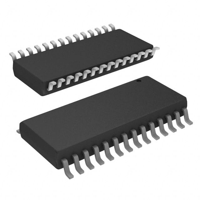
- Part No.:
- TLE7826GXUMA1
- Manufacturer:
- Infineon Technologies
- Category:
- Power Management - Specialized
- Package:
- 28-SOIC (0.295", 7.50mm Width)
- Datasheet:
-
 TLE7826GXUMA1.pdf
- Description:
- IC LDO VREG/LIN TXRX DSO-28
- Quantity:
- Payment:

- Shipping:

Inventory:1,972
Please send an inquiry. Send us your inquiry, and we will respond immediately.
Product details
Overview
TLE7826GXUMA1 from Infineon Technologies is an automotive System Basis Chip (SBC) with integrated 8-bit 8051-compatible MCU (32 kB Flash, 256 B RAM), dual low-side switches (1.2 A each), high-side LED driver (40 mA), Hall sensor supply (5 V/100 mA), 5 wake-up inputs, LIN 2.0 transceiver, 10-bit ADC, and LDO regulator (5 V/150 mA). It operates from -40 °C to 150 °C in PG-DSO-28-38 package and targets body control modules requiring consolidated power, communication, and actuation.
For engineers reviewing the TLE7826GXUMA1 datasheet, TLE7826GXUMA1 pinout, TLE7826GXUMA1 application, or TLE7826GXUMA1 equivalent, key selection criteria include verified LIN bus compliance, dual low-side switch current rating and thermal derating, integrated MCU boot ROM availability, wake-up input voltage thresholds (VBAT-referenced), and SBC active/stop mode current consumption under terminal 30 bias.
Technical Context
The device integrates two functionally distinct subsystems: an SBC with LIN transceiver, programmable window watchdog, overtemperature protection, and dual low-side/high-side drivers; and an XC885-based MCU with on-chip oscillator, JTAG debug interface, 3×16-bit timers, and UART/SSC peripherals. The SBC and MCU share supply domains (VCC = 5 V, VDDC = 2.5 V) but operate independently-enabling SBC-only wake-up without MCU activation.
Power management includes five defined modes: Standby (20 µA), Active, LIN Sleep (150 µA), RxD-Only (80 µA), and Stop Mode with cyclic wake (10 µA). Wake-up sources are LIN frames or any of five MONx inputs (VBAT-referenced, ±1 V hysteresis), with MON5 shared as HS-LED output. All analog measurement (Vbat, temp) uses a single 10-bit ADC with internal reference.
Key Specifications
| Parameter | Value and Actual Design Meaning |
|---|---|
| LIN Compliance | ISO 9141-2 & LIN 2.0 compliant transceiver; supports dominant/recessive signaling and slave node auto-synchronization |
| Low-Side Switches | LS1/LS2: 1.2 A continuous current, 200 mΩ RDS(on) @ TJ = 25 °C; short-circuit protected with foldback current limiting |
| HS-LED Driver | MON5/HS_LED pin: 40 mA constant-current sink; PWM-dimmable via SPI register; shares pin with wake-up input |
| ADC Resolution | 10-bit SAR ADC with 8-channel multiplexer; measures VBAT_SENSE (via external resistor divider) and internal die temperature |
| Flash Memory | 32 kB on-chip Flash for program/data; includes 12 kB boot ROM with LIN bootloader for field firmware updates |
| Operating Temp | Junction temperature range −40 °C to +150 °C; qualified per AEC-Q100 Grade 0; enables under-hood placement without external heatsinking |
| Supply Outputs | VCC = 5 V / 150 mA (logic supply); SUPPLY = 5 V / 100 mA (Hall sensor supply); VDDC = 2.5 V / 50 mA (MCU core) |
Pinout & Package
PG-DSO-28-38: 28-pin thermally enhanced exposed-pad SOIC package with 0.6 mm pitch, RoHS-compliant, green molding compound. Thermal resistance RthJA = 50 K/W (JEDEC standard PCB).
| Pin/Terminal | Circuit Role | Design Meaning |
|---|---|---|
| LS1 (Pin 6) | Low-side switch output | Controlled via SPI; drives relays or solenoids up to 1.2 A; includes overcurrent shutdown and thermal foldback |
| LS2 (Pin 5) | Low-side switch output | Independent SPI-controlled channel; identical specs to LS1; supports dual relay or lamp load control |
| MON1–MON4 (Pins 1,2,3,4) | Wake-up input | VBAT-referenced, bi-level sensitive; detect switch closures or sensor signals; ±1 V hysteresis prevents bounce |
| MON5/HS_LED (Pin 27) | Shared wake-up / LED driver | Configurable: as wake-up input (VBAT-referenced) or constant-current LED sink (40 mA); no simultaneous use |
| LIN (Pin 4) | LIN bus physical layer | Direct connection to LIN bus line; integrated pull-up/pull-down; meets ISO 9141-2 electrical requirements |
| VCC (Pin 23) | Main logic supply output | 5 V regulated LDO output; powers internal logic and external loads ≤150 mA; requires local 10 µF ceramic decoupling |
| SUPPLY (Pin 24) | Hall sensor supply | 5 V regulated output; dedicated for Hall ICs (e.g., TLE4966); 100 mA max; controlled via SPI enable bit |
| VS (Pin 25) | Main power input | Connects to battery (VBAT); accepts 5.5–28 V; internal ESD protection and reverse-polarity clamp |
Key Features
| Feature | Design Value |
|---|---|
| LIN Bootloader in ROM | 12 kB factory-programmed boot ROM enables firmware updates over LIN bus without external programmer |
| Programmable Window Watchdog | Configurable timeout and window width via SPI; resets MCU if not serviced within window; prevents runaway code execution |
| Dual Power Domains | Separate VCC (5 V) and VDDC (2.5 V) supplies isolate MCU core from I/O noise; improves ADC accuracy and timing stability |
| Integrated Temperature Sensing | On-die thermal sensor feeds 10-bit ADC; used for overtemperature shutdown at 165 °C and thermal derating of switch outputs |
| Stop Mode with Cyclic Wake | Ultra-low 10 µA sleep current with configurable wake interval (1–255 ms); enables periodic sensor polling without host intervention |
Applications
| Door Module Control | Seat Position Adjustment |
|---|---|
Use Scenario: Centralized control of power windows, locks, mirrors, and interior lighting in automotive door modules. IC Role / Device Role / Timing Role: SBC provides LIN communication, low-side switching for motor drivers and lamps, Hall supply for position sensors, and wake-up on button press. Use Value: Reduces BOM count by integrating MCU, LIN, power switches, and sensor supply in one PG-DSO-28 package; eliminates discrete LDO and transceiver. | Use Scenario: Motorized seat fore/aft, recline, and lumbar adjustment with position feedback via Hall sensors. IC Role / Device Role / Timing Role: Supplies Hall sensors (SUPPLY pin), reads position via ADC, drives motors via LS1/LS2, and reports status over LIN. Use Value: Enables closed-loop seat control with <100 µs response latency between Hall signal change and switch activation; supports ASIL-B functional safety goals. |
| Roof Module (Sunroof/Blind) | Trunk/Liftgate Actuation |
Use Scenario: Sunroof open/close and tilt control, plus integrated ambient light and rain sensing. IC Role / Device Role / Timing Role: Manages LIN command parsing, drives sunroof motor via LS1/LS2, supplies Hall sensors for position, and monitors VBAT for low-voltage cutoff. Use Value: Single-chip solution supports IP67-rated module design with only 28 pins; thermal shutdown prevents motor stall damage during obstruction events. | Use Scenario: Powered liftgate with obstacle detection, soft-close, and hands-free operation using proximity sensors. IC Role / Device Role / Timing Role: Interfaces ultrasonic/proximity sensors via ADC, controls latch and lift motors via LS1/LS2, and wakes on LIN request or MONx trigger. Use Value: Achieves <5 µA quiescent current in Stop Mode with cyclic wake, meeting OEM 100 µA total module leakage requirement over 30 days. |
Equivalent & Alternatives
The following parts are listed as comparable options for similar automotive SBC with integrated MCU applications.
| Alternative Part | Technical Difference | Application Difference | Selection Advice |
|---|---|---|---|
| TLF35584ESV50 | 32-bit ARM Cortex-M0+ MCU (1 MB Flash), dual CAN FD + LIN, higher integration (Buck/Boost regulators), no integrated low-side switches | Targets ADAS domain controllers requiring CAN FD and higher compute; lacks direct relay driving capability | Select when CAN FD backbone integration and >100 MHz processing are required; avoid if cost-sensitive relay control is primary need |
| MC33816 | 8-bit S12X MCU (64 kB Flash), LIN + SPI, dual low-side switches (1.5 A), no Hall supply or integrated ADC | Designed for simpler body nodes; requires external voltage reference and Hall supply regulator | Select for legacy S12X toolchain compatibility and higher switch current; add external LDO if Hall sensor supply needed |
Compared with TLF35584ESV50 and MC33816, TLE7826GXUMA1 uniquely balances MCU compute (8051), LIN, dual low-side drive, Hall supply, and ADC in one thermally robust package-making it optimal for cost-constrained, space-limited body electronics where mixed-signal integration reduces interconnect complexity.
Availability
TLE7826GXUMA1 is available at Aetrix Electronics and suitable for automotive door modules, seat control units, roof systems, and trunk actuation requiring stable component supply across extended temperature ranges and long production lifecycles.
Supply support for TLE7826GXUMA1 includes scheduled delivery planning, volume procurement assistance, BOM continuity management, traceable sourcing, and lifecycle availability coordination for OEM customers, industrial embedded developers, connected-device designers, and electronics production programs.
Manufacturer
Infineon Technologies is a German semiconductor manufacturer specializing in power management, automotive ICs, and security solutions, with global manufacturing and automotive qualification expertise.
The TLE78xx family delivers integrated System Basis Chips for automotive body electronics, combining power regulation, communication, and actuation to reduce system complexity and improve reliability in harsh environments.
FAQ
What is the maximum allowable junction temperature before thermal shutdown activates?
Thermal shutdown triggers at 165 °C measured at the die, as confirmed in Section 16.2 (Functional Range) of the Rev. 3.01 datasheet. The internal temperature sensor feeds the 10-bit ADC, enabling software-based thermal derating below shutdown threshold. Recovery occurs automatically after junction temperature falls below 155 °C hysteresis.
Can MON5 be used simultaneously as a wake-up input and HS-LED driver?
No-MON5/HS_LED is a time-multiplexed pin. Configuration is mutually exclusive: either enabled as a VBAT-referenced wake-up input (with ±1 V hysteresis) or as a 40 mA constant-current LED sink. The mode is selected via SPI register bit HSLED_EN; concurrent operation is electrically prohibited and not supported in firmware.
Does the integrated LIN transceiver support automatic baud rate detection?
Yes-the LIN transceiver implements automatic sync-field detection per LIN 2.0 specification. Upon wake-up, it samples the bus for dominant pulses and adjusts internal timing to match incoming frame baud rate (typically 19.2 kbps or 10.4 kbps), eliminating need for external crystal or precise clock calibration.
What is the minimum VBAT level at which the reset generator asserts RESET?
The undervoltage reset (UVR) circuit asserts active-low RESET when VBAT drops below 4.5 V (typical) with 100 mV hysteresis, as specified in Table 13 (Operating Range). This threshold is monitored continuously in all operating modes-including Stop Mode-and holds RESET until VBAT exceeds 4.6 V for ≥10 ms.
TLE7826GXUMA1 Specifications
- Product attributes
- Attribute value
- Manufacturer:
- Infineon Technologies
- Series:
- -
- Package/Case:
- 28-SOIC (0.295", 7.50mm Width)
- Packaging:
- Tape & Reel (TR)
- Product Status:
- Obsolete
- Applications:
- Special Purpose
- Current - Supply:
- -
- Voltage - Supply:
- 3.9V ~ 27V
- Operating Temperature:
- -40°C ~ 150°C
- Grade:
- -
- Qualification:
- -
- Mounting Type:
- Surface Mount
- Supplier Device Package:
- PG-DSO-28
TLE7826GXUMA1 FAQ
1.How can I place an order for TLE7826GXUMA1 through Aetrix?
Please submit a Request for Quotation (RFQ) for TLE7826GXUMA1 on Aetrix. Our sales agent will provide a competitive quotation and guide you through the order confirmation once you accept the terms.
2.Are the price and stock information for TLE7826GXUMA1 reliable?
The price and inventory of TLE7826GXUMA1 are updated periodically and may fluctuate due to market conditions. Stock and pricing data are typically refreshed every 24 hours. Quotation validity for TLE7826GXUMA1 is usually 5 days.
3.What payment methods are accepted for TLE7826GXUMA1?
We accept Wire Transfer, PayPal, Credit Card, Western Union, MoneyGram, and Escrow for TLE7826GXUMA1 transactions.
Note: Certain payment methods may incur a processing fee.
4.How is shipping managed for TLE7826GXUMA1?
TLE7826GXUMA1 orders can be shipped via leading logistics carriers, including DHL, UPS, FedEx, TNT, or Registered Mail.
Once your TLE7826GXUMA1 order is processed, you will receive an email with the shipment details and tracking number.
Note: Tracking information may take up to 24 hours to appear. Express delivery typically takes 3–5 business days.
5.How can I obtain technical support or documentation for TLE7826GXUMA1?
For technical support, including TLE7826GXUMA1 datasheets, pinout diagrams, or application guidance, please contact our engineering support team. They can provide detailed documentation and assistance for your TLE7826GXUMA1 requirements.
6.How does Aetrix verify that TLE7826GXUMA1 is sourced from the original manufacturer or authorized distributors?
All TLE7826GXUMA1 products on Aetrix are procured from qualified distributors and authorized channels. Our dedicated quality assurance team conducts strict verification, including traceability checks and, if necessary, third-party testing. This ensures that TLE7826GXUMA1 meets industry standards.
7.What is the process for return or replacement of TLE7826GXUMA1?
All TLE7826GXUMA1 units undergo pre-shipment inspection (PSI). If there is an issue with TLE7826GXUMA1, returns or replacements are accepted under the following conditions:
1.Quantity discrepancies, incorrect items, or visible external defects (such as breakage or corrosion), acknowledged by Aetrix.
2.The issue is reported within 90 days of delivery.
3.The TLE7826GXUMA1 part is unused and in its original packaging.
Return procedure for TLE7826GXUMA1:
1.Submit a request within 90 days.
2.Obtain a Return Material Authorization (RMA) from Aetrix.
TLE7826GXUMA1 Tags

-
TPS2511DGNR
Texas Instruments

-
UTC2000/MG
Microchip Technology

-
TUSB320HAIRWBR
Texas Instruments

-
TPS61252DSGR
Texas Instruments

-
PI5USB30216CXUAEX
Diodes Incorporated

-
SN6501DBVR
Texas Instruments

-
CYPD3177-24LQXQT
Infineon Technologies
-
SN6501QDBVRQ1
Texas Instruments

-
STUSB1600AQTR
STMicroelectronics

-
SN6505BDBVR
Texas Instruments
-
SN6501DBVT
Texas Instruments

-
TPS65150PWPR
Texas Instruments
Tech Hub

18650 battery guide covering lithium-ion cell basics, 3.6V/3.7V voltage, 4.2V charging, mAh and Wh capacity, protected cells, chargers, BMS, series-parallel packs, holders, welding and sourcing checks.…

Hall effect sensor guide covering working principle, linear and digital sensors, Arduino circuits, current sensing, speed detection, automotive applications, A3144 examples, signal filtering and datash…

Product Change Notification guide for electronic components, covering PCN meaning, PCN vs PDN/EOL, common change types, risk levels, form-fit-function review, engineering validation, BOM control, LTB/L…

A practical guide to blend door actuators, covering HVAC function, symptoms, location, AC and heater issues, reset and calibration, replacement cost, electrical diagnosis, compatibility checks, and rep…

Engineering guide to Raspberry Pi alternatives, covering chip-level differences, Orange Pi, ROCK, Jetson, Banana Pi, NanoPi, Compute Module, Pico, GPIO, camera, HAT compatibility, and replacement risks…

Engineering guide to dynamic load response testing for high-current buck converters, covering load step setup, slew rate, Vcore undershoot, overshoot, recovery time, probe location, output capacitors a…

Engineering guide to output capacitor selection for ASIC Vcore rails, covering bulk capacitors, polymer capacitors, MLCC decoupling, DC bias, ESR, ESL, placement, transient response and substitution ri…

Engineering guide to high-current ASIC Vcore rails, covering 12-phase buck architecture, PMBus control, dynamic load testing, output capacitor networks, smart power stage selection, thermal design and …

Voltage regulator guide covering linear, LDO, 7805, Zener, adjustable, buck, VRM and alternator regulators, with design checks, testing methods, troubleshooting and datasheet-based selection.

Amplifier guide covering voltage, current and power amplification, gain, feedback, amplifier classes, audio and RF applications, op-amp circuits, transimpedance amplifiers, datasheet selection and trou…


