Send an Inquiry

To receive a quote for your project, please fill in the following information, and we’ll get back to you promptly.

Name*
Company*
Email Address*
Phone/WhatsApp
Part Number*
Quantity*
Message
Submit Inventory List

Please fill in the following information, and we’ll get back to you promptly.

Name*
Company*
Email Address*
Phone/WhatsApp
Upload My List
Message

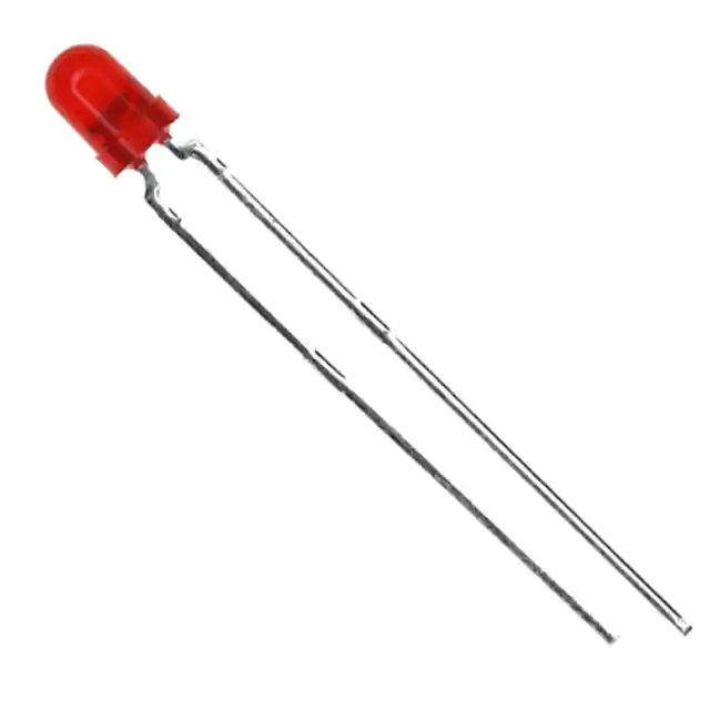
Vishay Semiconductor Opto Division TLHR4400
Part No.:
TLHR4400
Manufacturer:
Vishay Semiconductor Opto Division
Category:
LED Indication - Discrete
Package:
Radial
Datasheet:
AetrixTLHR4400.pdf
Description:
LED RED DIFFUSED T-1 T/H
Quantity:
Payment:
Payment
Shipping:
Shipping

Inventory:6,294

Please send an inquiry. Send us your inquiry, and we will respond immediately.

Part Number
Quantity*
Price
Name*
Company
Email*
Comments

Product details

Overview

TLHR4400 from Vishay Semiconductors is a red light-emitting diode (LED) in a 3 mm tinted diffused plastic package (T-1), delivering 1.6–13 mcd luminous intensity at 10 mA, with dominant wavelength 612–625 nm and forward voltage 2–3 V at 20 mA. It serves as an on/off indicator or status light in industrial control panels and consumer electronics interfaces.

For engineers reviewing the TLHR4400 datasheet, TLHR4400 pinout, TLHR4400 application, or TLHR4400 equivalent, this page provides verified optical-electrical specs, package geometry, viewing angle behavior, absolute maximum ratings, and validated alternative LEDs for visual indication design.

Technical Context

The TLHR4400 uses GaAsP-on-GaP epitaxial technology to achieve red emission with high on-off contrast and stable chromaticity across temperature. Its ±30° angle of half intensity enables wide-angle visibility without lens distortion.

Rated for DC and pulsed operation up to 1 A surge current (10 μs), it supports reliable indicator function in environments with ambient temperatures from –40 °C to +100 °C and junction temperatures up to 100 °C.

Key Specifications

Parameter Value and Actual Design Meaning
Luminous intensity 1.6–13 mcd at 10 mA - defines visible brightness level under standard test conditions for consistent human-perceived illumination
Dominant wavelength 612–625 nm - specifies red spectral output range ensuring color consistency across production lots
Forward voltage 2–3 V at 20 mA - determines series resistor value needed for stable biasing in 3.3 V or 5 V indicator circuits
Angle of half intensity ±30° - sets usable viewing cone width for front-panel indicators requiring broad operator visibility
Absolute max forward current 30 mA DC - establishes continuous drive limit to prevent thermal degradation and lumen depreciation
Reverse voltage rating 6 V - defines maximum allowable reverse bias before leakage or breakdown compromises reliability
Junction-to-ambient thermal resistance 400 K/W - quantifies self-heating under load; informs derating requirements above 25 °C ambient

Pinout & Package

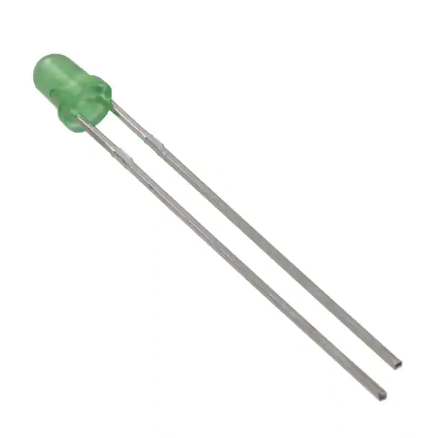
TLHR4400 is housed in a standard Ø 3 mm (T-1) tinted diffused plastic package with axial leads. Cathode is identified by a flat edge on the lens housing and shorter lead per Vishay mechanical drawing 6.544-5255.01-4.

Pin/Terminal Circuit Role Design Meaning
Anode (longer lead) Positive terminal Connects to current-limiting resistor and supply rail; polarity must be observed to avoid reverse-bias damage
Cathode (shorter lead, flat side) Negative terminal Common return path; marking aligns with PCB silkscreen cathode indicator for automated assembly verification

Key Features

Feature Design Value
Standard T-1 (Ø 3 mm) package Enables drop-in replacement in legacy 3 mm LED footprints without board redesign or tooling change
Wide ±30° viewing angle Provides uniform brightness across 60° arc-critical for panel-mounted status lights viewed from multiple angles
Luminous intensity binning Groups TLHR4400 units by measured mcd range (L group: 1–2 mcd), ensuring consistent brightness within a single reel
Tinted diffused lens Softens point-source glare and eliminates hot spots-improves readability and reduces eye fatigue in low-light environments
GaAsP-on-GaP chip technology Delivers stable red chromaticity with minimal wavelength shift over temperature (Δλd < 0.1 nm/°C)

Applications

Status Indicator Power-On Confirmation

Use Scenario: Front-panel LED on industrial PLC module indicating operational readiness.

IC Role / Device Role / Timing Role: Visual status emitter - no timing or logic function; driven statically or via microcontroller GPIO.

Use Value: High on-off contrast and wide viewing angle ensure immediate recognition by maintenance personnel across 0–60° horizontal plane.

Use Scenario: Power-good indicator on embedded power supply board.

IC Role / Device Role / Timing Role: Steady-state DC indicator - biased continuously during nominal operation.

Use Value: 30 mA absolute max rating and 100 °C junction temperature support long-term reliability under continuous 5 V rail operation.

Legend Illumination Maintenance Light

Use Scenario: Backlighting engraved labels on HVAC control panel overlays.

IC Role / Device Role / Timing Role: Constant-current light source - paired with diffuser film to homogenize output.

Use Value: Tinted diffused lens eliminates specular reflection, enabling even illumination of translucent polycarbonate legends.

Use Scenario: Portable handheld diagnostic tool with battery-powered indicator.

IC Role / Device Role / Timing Role: Low-power visual cue - operated at 10 mA to extend coin-cell battery life.

Use Value: 1.6–13 mcd intensity range allows selection of appropriate brightness bin (e.g., L group) to balance visibility and power consumption.

Equivalent & Alternatives

The following parts are listed as comparable options for similar red LED indicator applications.

Alternative Part Technical Difference Application Difference Selection Advice
TLHR4401 Higher typical luminous intensity (14 mcd vs. 13 mcd at 10 mA); same wavelength and VF range Better suited for applications requiring higher brightness in ambient-lit environments Select TLHR4401 when >13 mcd is needed without changing drive circuit or footprint
TLHR4405 Further increased intensity (15 mcd typ.), wider min–max luminous intensity spread (6.3–12.5 mcd) Used where brightness uniformity is less critical than peak output (e.g., non-critical warning lights) Choose TLHR4405 only if system-level brightness tolerance allows wider binning; not recommended for matched arrays

Compared with TLHR4400, TLHR4401 offers marginally higher brightness while maintaining identical package, pinout, and electrical envelope-making it a direct upgrade for visibility-critical indicators. TLHR4405 trades intensity consistency for higher peak output, limiting its use in applications requiring uniform appearance across multiple units.

Availability

TLHR4400 is available at Aetrix Electronics and suitable for industrial HMI panels, consumer appliance interfaces, and embedded diagnostic tools requiring stable component supply and consistent red indicator performance.

Supply support for TLHR4400 includes scheduled delivery planning, volume procurement assistance, BOM continuity management, traceable sourcing, and lifecycle availability coordination for OEM customers, industrial embedded developers, connected-device designers, and electronics production programs.

Manufacturer

Vishay Semiconductors designs discrete semiconductors and passive components with emphasis on reliability, precision, and long-term manufacturability for industrial and automotive markets.

The TLHR4400 belongs to Vishay's standard 3 mm LED product line, engineered specifically for general-purpose visual indication where consistent color, wide viewing angle, and mechanical interchangeability are primary design requirements.

FAQ

What is the luminous intensity range of TLHR4400 at 10 mA?

The TLHR4400 has a luminous intensity range of 1.6–13 mcd at 10 mA, as specified in the Vishay datasheet (Document Number: 83006, Rev. 3.8). This range reflects factory binning into the "L" group (1–2 mcd min–max), ensuring consistent brightness within each packaging unit. The TLHR4400 is not rated for intensity beyond 13 mcd at this current.

Does TLHR4400 have a built-in current-limiting resistor?

No, TLHR4400 is a bare LED die in a 3 mm package and does not include an integrated current-limiting resistor. External series resistance must be calculated based on supply voltage and the TLHR4400's forward voltage (2–3 V at 20 mA) to maintain operation within its 30 mA absolute maximum DC rating.

What is the correct polarity identification for TLHR4400?

The TLHR4400 cathode is marked by a flat edge on the lens housing and corresponds to the shorter lead. The anode is the longer lead. This polarity alignment follows Vishay's standard orientation for axial-leaded LEDs and must be observed during PCB layout and assembly to prevent reverse-bias damage.

Can TLHR4400 operate reliably at 100 °C ambient temperature?

Yes, TLHR4400 is rated for operation from –40 °C to +100 °C ambient temperature. However, at 100 °C, its forward voltage decreases and luminous intensity drops approximately 30% relative to 25 °C values. Derating of forward current below 30 mA may be required to maintain junction temperature ≤ 100 °C under sustained high-temperature conditions.

Is TLHR4400 compatible with reflow soldering processes?

No-TLHR4400 is intended for wave soldering or hand soldering only. Its plastic package is not rated for reflow profiles; the maximum soldering temperature is 260 °C for ≤5 seconds at 2 mm from the body. Reflow exposure risks lens discoloration, internal delamination, and irreversible luminous flux loss.

TLHR4400 Specifications

Product attributes
Attribute value
Manufacturer:
Vishay Semiconductor Opto Division
Series:
TLH.44
Package/Case:
Radial
Packaging:
Bulk
Product Status:
Active
Color:
Red
Configuration:
Standard
Lens Color:
-
Lens Transparency:
Diffused
Millicandela Rating:
13mcd
Lens Style:
Round with Domed Top
Lens Size:
3mm, T-1
Voltage - Forward (Vf) (Typ):
2V
Current - Test:
10mA
Viewing Angle:
60°
Mounting Type:
Through Hole
Wavelength - Dominant:
619nm
Wavelength - Peak:
635nm
Features:
-
Grade:
-
Qualification:
-
Supplier Device Package:
T-1
Size / Dimension:
-

TLHR4400 FAQ

1.How can I place an order for TLHR4400 through Aetrix?

Please submit a Request for Quotation (RFQ) for TLHR4400 on Aetrix. Our sales agent will provide a competitive quotation and guide you through the order confirmation once you accept the terms.

2.Are the price and stock information for TLHR4400 reliable?

The price and inventory of TLHR4400 are updated periodically and may fluctuate due to market conditions. Stock and pricing data are typically refreshed every 24 hours. Quotation validity for TLHR4400 is usually 5 days.

3.What payment methods are accepted for TLHR4400?

We accept Wire Transfer, PayPal, Credit Card, Western Union, MoneyGram, and Escrow for TLHR4400 transactions.

Note: Certain payment methods may incur a processing fee.

4.How is shipping managed for TLHR4400?

TLHR4400 orders can be shipped via leading logistics carriers, including DHL, UPS, FedEx, TNT, or Registered Mail.

Once your TLHR4400 order is processed, you will receive an email with the shipment details and tracking number.

Note: Tracking information may take up to 24 hours to appear. Express delivery typically takes 3–5 business days.

5.How can I obtain technical support or documentation for TLHR4400?

For technical support, including TLHR4400 datasheets, pinout diagrams, or application guidance, please contact our engineering support team. They can provide detailed documentation and assistance for your TLHR4400 requirements.

6.How does Aetrix verify that TLHR4400 is sourced from the original manufacturer or authorized distributors?

All TLHR4400 products on Aetrix are procured from qualified distributors and authorized channels. Our dedicated quality assurance team conducts strict verification, including traceability checks and, if necessary, third-party testing. This ensures that TLHR4400 meets industry standards.

7.What is the process for return or replacement of TLHR4400?

All TLHR4400 units undergo pre-shipment inspection (PSI). If there is an issue with TLHR4400, returns or replacements are accepted under the following conditions:

1.Quantity discrepancies, incorrect items, or visible external defects (such as breakage or corrosion), acknowledged by Aetrix.

2.The issue is reported within 90 days of delivery.

3.The TLHR4400 part is unused and in its original packaging.

Return procedure for TLHR4400:

1.Submit a request within 90 days.

2.Obtain a Return Material Authorization (RMA) from Aetrix.

TLHR4400 Tags

  • TLHR4400
  • TLHR4400 PDF
  • TLHR4400 Datasheet
  • TLHR4400 Specifications
  • TLHR4400 Images
  • Vishay Semiconductor Opto Division
  • Vishay Semiconductor Opto Division TLHR4400
  • Buy TLHR4400
  • TLHR4400 Price
  • TLHR4400 Distributor
  • TLHR4400 Supplier
  • TLHR4400 Wholesale
Related Products
LTST-C281KRKT
LTST-C281KRKT

Lite-On Inc.

150060GS75000
150060GS75000

Würth Elektronik

150060VS75000
150060VS75000

Würth Elektronik

150060AS75000
150060AS75000

Würth Elektronik

150060YS75000
150060YS75000

Würth Elektronik

150060SS75000
150060SS75000

Würth Elektronik

150060BS75000
150060BS75000

Würth Elektronik

151031VS06000
151031VS06000

Würth Elektronik

151033RS03000
151033RS03000

Würth Elektronik

150080BS75000
150080BS75000

Würth Elektronik

150080GS75000
150080GS75000

Würth Elektronik

150141GS73100
150141GS73100

Würth Elektronik

Tech Hub

Search

Search

PRODUCT

PRODUCT

PHONE

PHONE

USER

USER