Send an Inquiry

To receive a quote for your project, please fill in the following information, and we’ll get back to you promptly.

Name*
Company*
Email Address*
Phone/WhatsApp
Part Number*
Quantity*
Message
Submit Inventory List

Please fill in the following information, and we’ll get back to you promptly.

Name*
Company*
Email Address*
Phone/WhatsApp
Upload My List
Message

Vishay Semiconductor Opto Division TLLY4400
Part No.:
TLLY4400
Manufacturer:
Vishay Semiconductor Opto Division
Category:
LED Indication - Discrete
Package:
Radial
Datasheet:
AetrixTLLY4400.pdf
Description:
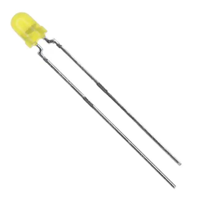
LED YELLOW DIFFUSED T-1 T/H
Quantity:
Payment:
Payment
Shipping:
Shipping

Inventory:4,458

Please send an inquiry. Send us your inquiry, and we will respond immediately.

Part Number
Quantity*
Price
Name*
Company
Email*
Comments

Product details

Overview

TLLY4400 from Vishay Semiconductors is a low-current yellow LED in a 3 mm tinted diffused package, specified at 2 mA forward current, with dominant wavelength 581–594 nm, forward voltage 2.4–2.9 V, and luminous intensity 0.63–1.2 mcd. It serves as an indicator in space-constrained, low-power DC circuits requiring stable visual status feedback under ambient lighting.

For engineers reviewing the TLLY4400 datasheet, TLLY4400 pinout, TLLY4400 application, or TLLY4400 equivalent, this page delivers verified optical, electrical, and packaging data - including absolute maximum ratings, luminous intensity binning, thermal resistance (800 K/W), and compatibility with CMOS/MOS logic-level drive - to support reliable indicator selection in battery-powered and industrial control designs.

Technical Context

The TLLY4400 uses GaAsP-on-GaP semiconductor technology optimized for visible yellow emission, with ±25° viewing angle and tested at 25 ms pulse width for luminous intensity and wavelength measurements. Its low 2 mA test current enables direct interface with microcontroller GPIOs without external current-limiting resistors in many cases.

Rated for operation from –40 °C to +100 °C ambient, the device features 6 V reverse voltage tolerance, 7 mA DC forward current limit, and 20 mW power dissipation at ≤84 °C ambient - making it suitable for sealed enclosures and thermally unmanaged environments where self-heating must be minimized.

Key Specifications

Parameter Value and Actual Design Meaning
Luminous intensity 0.63–1.2 mcd at 2 mA - sufficient for clear visibility in indoor/low-ambient-light panels without excessive power draw
Dominant wavelength 581–594 nm - standardized yellow output compliant with IEC 60068-2-17 color classification group "0" through "6"
Forward voltage 2.4–2.9 V at 2 mA - compatible with 3.3 V and 5 V logic rails using minimal series resistance (e.g., ~330 Ω from 5 V)
Viewing angle ±25° half-intensity - provides focused yet readable indication within narrow panel apertures
Thermal resistance 800 K/W junction-to-ambient - requires no heatsinking but limits continuous duty cycle above 2 mA in enclosed spaces
Absolute max forward current 7 mA DC - defines safe operating ceiling for pulsed or intermittent use beyond nominal 2 mA rating
Reverse voltage 6 V - protects against accidental reverse polarity in manual wiring or shared PCB traces

Pinout & Package

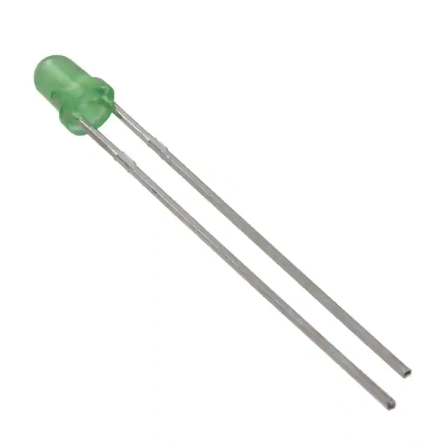
Package: Ø3 mm radial-leaded, tinted diffused epoxy lens with cathode-indicating flat side and standard 2.54 mm lead pitch. Leads are tin-plated copper, RoHS-compliant, and rated for 260 °C soldering (5 s, 2 mm from body).

Pin/Terminal Circuit Role Design Meaning
Anode (longer lead) Positive terminal Connects to supply rail or active-high driver; forward bias initiates photon emission
Cathode (shorter lead / flat side) Negative terminal Reference node for current return; polarity-sensitive - reverse connection blocks conduction

Key Features

Feature Design Value
Low power consumption Operates at 2 mA nominal - draws <6 µW at 3 V, enabling multi-LED arrays on coin-cell or energy-harvesting supplies
CMOS/MOS compatible Forward voltage range (2.4–2.9 V) aligns with standard logic high thresholds - eliminates need for level-shifting circuitry
Luminous intensity binning IVmin/IVmax ≤ 0.5 per packing unit - ensures consistent brightness across LEDs in same batch for uniform panel appearance
Wide temperature operation –40 °C to +100 °C ambient range - supports deployment in automotive dashboards, industrial HMI, and outdoor enclosures
Standardized wavelength grouping Yellow dominant wavelength binned into 3 nm groups (e.g., 581–584 nm, 583–586 nm) - enables precise color matching across production lots

Applications

Industrial Control Panel Indicator Portable Medical Device Status Light

Use Scenario: Visual status indication on DIN-rail mounted PLC I/O modules with limited board space and no active cooling.

IC Role / Device Role / Timing Role: Passive optical indicator driven directly from microcontroller GPIO pins at 2 mA.

Use Value: Low 2 mA drive requirement avoids burdening MCU outputs; 800 K/W RthJA prevents thermal runaway in sealed metal enclosures.

Use Scenario: Battery-operated glucose meter displaying measurement completion and error states.

IC Role / Device Role / Timing Role: Human-readable status emitter powered by CR2032 cell with >2-year shelf life.

Use Value: 0.63–1.2 mcd output remains clearly visible under indoor lighting while consuming <1 µA average current in pulsed mode.

Automotive Dashboard Warning Light Consumer Appliance Power-On Indicator

Use Scenario: Engine oil pressure warning lamp integrated into instrument cluster backlighting layer.

IC Role / Device Role / Timing Role: Yellow-emitting discrete LED paired with diffuser film for soft, glare-free illumination.

Use Value: 581–594 nm dominant wavelength meets automotive yellow signal standards; ±25° viewing angle matches lens aperture geometry.

Use Scenario: Standby power indicator on Wi-Fi-enabled smart thermostat with 3.3 V system rail.

IC Role / Device Role / Timing Role: Always-on visual cue powered via LDO-regulated 3.3 V, drawing <10 µA average in blink mode.

Use Value: 2.4–2.9 V VF allows direct connection to 3.3 V rail with only 33 Ω series resistor - simplifies BOM and layout.

Equivalent & Alternatives

The following parts are listed as comparable options for similar LED indicator applications.

Alternative Part Technical Difference Application Difference Selection Advice
TLLY4401 Luminous intensity 1–2 mcd (vs. 0.63–1.2 mcd); otherwise identical optical/electrical specs and package Better suited for higher-ambient-light environments (e.g., kiosk front panels) where increased brightness improves readability Select TLLY4401 when >1 mcd minimum output is required; TLLY4400 preferred for ultra-low-power or dimmed UI contexts
TLLE4400 Vishay's newer 3 mm yellow LED with same 581–594 nm λd, but improved 1.5–3.0 mcd output and 500 K/W RthJA Enables higher drive currents (up to 10 mA) and better thermal margin in compact assemblies Choose TLLE4400 for new designs needing higher brightness or extended thermal headroom; TLLY4400 remains valid for legacy replacements

Compared with TLLY4400, TLLY4401 offers higher minimum luminous intensity without changing drive requirements, while TLLE4400 provides both higher output and lower thermal resistance - making it more robust for sustained operation but requiring design review for forward voltage and footprint compatibility.

Availability

TLLY4400 is available at Aetrix Electronics and suitable for industrial control panels, portable medical devices, automotive dashboard indicators, and consumer appliance power-on circuits requiring stable component supply and long-term obsolescence management.

Supply support for TLLY4400 includes scheduled delivery planning, volume procurement assistance, BOM continuity management, traceable sourcing, and lifecycle availability coordination for OEM customers, industrial embedded developers, connected-device designers, and electronics production programs.

Manufacturer

Vishay Semiconductors is a global leader in discrete semiconductors and passive components, specializing in high-reliability optoelectronics, power MOSFETs, and precision resistors for industrial, automotive, and computing markets.

The TLLY4400 belongs to Vishay's low-current 3 mm LED family designed specifically for ultra-low-power visual indication in space- and energy-constrained applications - emphasizing consistency, longevity, and ease of integration with digital logic.

FAQ

What is the recommended forward current for continuous operation of the TLLY4400?

The TLLY4400 is specified and characterized at 2 mA forward current, which is its nominal operating point for luminous intensity and forward voltage ratings. While its absolute maximum DC forward current is 7 mA, continuous operation above 2 mA increases self-heating and reduces lifetime - especially given its 800 K/W thermal resistance. For reliable long-term use, maintain ≤2 mA unless transient pulses are used with appropriate duty cycling. The TLLY4400 datasheet confirms all key parameters are guaranteed at IF = 2 mA.

Does the TLLY4400 have a built-in current-limiting resistor?

No, the TLLY4400 is a bare LED die in a 3 mm package with no integrated current-limiting resistor. It requires an external series resistor or constant-current driver to regulate forward current. At 5 V supply, a 1.2 kΩ resistor sets IF ≈ 2 mA (using typical VF = 2.6 V); at 3.3 V, a 330 Ω resistor achieves the same. This discrete configuration preserves flexibility in brightness tuning and thermal management - a design choice confirmed in the Vishay TLLY4400 datasheet section "Optical and Electrical Characteristics."

Is the TLLY4400 suitable for outdoor applications?

The TLLY4400 is rated for operation from –40 °C to +100 °C ambient temperature and features a tinted diffused epoxy lens that resists UV-induced yellowing per Vishay's material categorization guidelines. However, its luminous intensity (0.63–1.2 mcd) is optimized for indoor or shaded environments - not direct sunlight. For outdoor signage or daylight-visible indicators, higher-intensity alternatives like TLLE4400 or surface-mount high-brightness LEDs are recommended. The TLLY4400 datasheet explicitly positions it for "low power DC circuits," not solar-exposed deployments.

How does the luminous intensity binning work for the TLLY4400?

The TLLY4400 is shipped in brightness-binned lots where IVmin/IVmax ≤ 0.5 within each packing unit - meaning the dimmest and brightest units in a reel differ by no more than 2× in luminous intensity. This ensures uniform appearance across multi-LED panels. Vishay assigns standard bin codes (K = 0.63–1.25 mcd, L = 1–2 mcd) per the "Luminous Intensity Classification" table. The TLLY4400 corresponds to bin K; its datasheet specifies min 0.63 mcd and typ 1.2 mcd at 2 mA - values validated per IEC 60068-2-17 testing protocols.

Can the TLLY4400 be reflow soldered?

No, the TLLY4400 is a through-hole radial-leaded LED intended for wave soldering or hand soldering only. Its package is not rated for reflow profiles: the maximum soldering temperature is 260 °C for 5 seconds at 2 mm from the body, per the "Absolute Maximum Ratings" table. Reflow exposes the entire epoxy body to sustained high temperatures (>200 °C for >60 s), risking lens discoloration, internal delamination, or bond wire failure. The Vishay TLLY4400 datasheet explicitly references tape-and-reel handling (AS12/MS12) and wave-solder-compatible dimensions - confirming its through-hole process alignment.

TLLY4400 Specifications

Product attributes
Attribute value
Manufacturer:
Vishay Semiconductor Opto Division
Series:
-
Package/Case:
Radial
Packaging:
Bulk
Product Status:
Active
Color:
Yellow
Configuration:
Standard
Lens Color:
-
Lens Transparency:
Diffused
Millicandela Rating:
1.2mcd
Lens Style:
Round with Domed Top
Lens Size:
3.20mm Dia
Voltage - Forward (Vf) (Typ):
2.4V
Current - Test:
2mA
Viewing Angle:
50°
Mounting Type:
Through Hole
Wavelength - Dominant:
588nm
Wavelength - Peak:
585nm
Features:
-
Grade:
-
Qualification:
-
Supplier Device Package:
T-1
Size / Dimension:
-

TLLY4400 FAQ

1.How can I place an order for TLLY4400 through Aetrix?

Please submit a Request for Quotation (RFQ) for TLLY4400 on Aetrix. Our sales agent will provide a competitive quotation and guide you through the order confirmation once you accept the terms.

2.Are the price and stock information for TLLY4400 reliable?

The price and inventory of TLLY4400 are updated periodically and may fluctuate due to market conditions. Stock and pricing data are typically refreshed every 24 hours. Quotation validity for TLLY4400 is usually 5 days.

3.What payment methods are accepted for TLLY4400?

We accept Wire Transfer, PayPal, Credit Card, Western Union, MoneyGram, and Escrow for TLLY4400 transactions.

Note: Certain payment methods may incur a processing fee.

4.How is shipping managed for TLLY4400?

TLLY4400 orders can be shipped via leading logistics carriers, including DHL, UPS, FedEx, TNT, or Registered Mail.

Once your TLLY4400 order is processed, you will receive an email with the shipment details and tracking number.

Note: Tracking information may take up to 24 hours to appear. Express delivery typically takes 3–5 business days.

5.How can I obtain technical support or documentation for TLLY4400?

For technical support, including TLLY4400 datasheets, pinout diagrams, or application guidance, please contact our engineering support team. They can provide detailed documentation and assistance for your TLLY4400 requirements.

6.How does Aetrix verify that TLLY4400 is sourced from the original manufacturer or authorized distributors?

All TLLY4400 products on Aetrix are procured from qualified distributors and authorized channels. Our dedicated quality assurance team conducts strict verification, including traceability checks and, if necessary, third-party testing. This ensures that TLLY4400 meets industry standards.

7.What is the process for return or replacement of TLLY4400?

All TLLY4400 units undergo pre-shipment inspection (PSI). If there is an issue with TLLY4400, returns or replacements are accepted under the following conditions:

1.Quantity discrepancies, incorrect items, or visible external defects (such as breakage or corrosion), acknowledged by Aetrix.

2.The issue is reported within 90 days of delivery.

3.The TLLY4400 part is unused and in its original packaging.

Return procedure for TLLY4400:

1.Submit a request within 90 days.

2.Obtain a Return Material Authorization (RMA) from Aetrix.

TLLY4400 Tags

  • TLLY4400
  • TLLY4400 PDF
  • TLLY4400 Datasheet
  • TLLY4400 Specifications
  • TLLY4400 Images
  • Vishay Semiconductor Opto Division
  • Vishay Semiconductor Opto Division TLLY4400
  • Buy TLLY4400
  • TLLY4400 Price
  • TLLY4400 Distributor
  • TLLY4400 Supplier
  • TLLY4400 Wholesale
Related Products
LTST-C281KRKT
LTST-C281KRKT

Lite-On Inc.

150060GS75000
150060GS75000

Würth Elektronik

150060VS75000
150060VS75000

Würth Elektronik

150060AS75000
150060AS75000

Würth Elektronik

150060YS75000
150060YS75000

Würth Elektronik

150060SS75000
150060SS75000

Würth Elektronik

150060BS75000
150060BS75000

Würth Elektronik

151031VS06000
151031VS06000

Würth Elektronik

151033RS03000
151033RS03000

Würth Elektronik

150080BS75000
150080BS75000

Würth Elektronik

150080GS75000
150080GS75000

Würth Elektronik

150141GS73100
150141GS73100

Würth Elektronik

Tech Hub

Search

Search

PRODUCT

PRODUCT

PHONE

PHONE

USER

USER