Vishay Semiconductor Opto Division TLPR5600
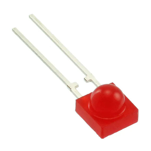
- Part No.:
- TLPR5600
- Manufacturer:
- Vishay Semiconductor Opto Division
- Category:
- LED Indication - Discrete
- Package:
- Radial, Side View
- Datasheet:
-
TLPR5600.pdf
- Description:
- LED RED DIFF SIDE VIEW T/H R/A
- Quantity:
- Payment:

- Shipping:

Inventory:5,041
Please send an inquiry. Send us your inquiry, and we will respond immediately.
Product details
Overview
TLPR5600 from Vishay Semiconductors is a super red 5 mm side-view LED with dominant wavelength of 630 nm, luminous intensity of 3.5 mcd at 10 mA, and ±80° viewing angle - designed for front-panel status indication in industrial HMIs, appliance control panels, and instrumentation displays.
For engineers reviewing the TLPR5600 datasheet, TLPR5600 pinout, TLPR5600 application, or TLPR5600 equivalent, this device requires attention to forward voltage (2–3 V @ 20 mA), thermal resistance (500 K/W), luminous intensity binning (R group: 10–20 mcd), and DC/pulse operation compatibility within its -40°C to +100°C operating range.
Technical Context
The TLPR5600 uses GaAsP-on-GaP epitaxial technology to achieve super red emission with peak wavelength at 640 nm and narrow spectral width. Its side-view 5 mm package enables compact PCB mounting with horizontal light emission aligned to panel edges.
Rated for 20 mA DC forward current and 1 A surge (tp ≤ 10 μs), it operates with 6 V reverse voltage tolerance and exhibits 50 pF junction capacitance - supporting stable low-speed indicator signaling without high-frequency parasitic effects.
Key Specifications
| Parameter | Value and Actual Design Meaning |
|---|---|
| Color | Super red - optimized for human eye sensitivity in status-indicator applications requiring high visual contrast against neutral backgrounds. |
| Luminous intensity | 3.5 mcd typical at 10 mA - sufficient brightness for indoor panel indication without glare or excessive power draw. |
| Dominant wavelength | 630 nm - places emission in the high-luminosity region of CIE 1931 photopic curve for optimal perceived brightness. |
| Viewing angle | ±80° - enables wide-angle visibility across broad operator positions without mechanical aiming. |
| Forward voltage | 2–3 V at 20 mA - compatible with standard 3.3 V and 5 V logic-supply rails using simple series resistor biasing. |
| Thermal resistance | 500 K/W - requires thermal-aware layout (e.g., minimal copper isolation) when operated near max 20 mA in enclosed environments. |
| Operating temperature | -40°C to +100°C - supports deployment in automotive cabin controls, industrial PLC I/O modules, and outdoor-rated enclosures. |
Pinout & Package
TLPR5600 uses a standard 5 mm side-view package with axial leads: anode (longer lead) and cathode (shorter lead, flat side on housing). No polarity marking on lens; identification relies on lead length and housing flat.
| Pin/Terminal | Circuit Role | Design Meaning |
|---|---|---|
| Anode | Positive terminal | Connects to current source or MCU GPIO via current-limiting resistor; forward bias initiates photon emission. |
| Cathode | Ground reference terminal | Typically tied to system ground or sink driver; polarity reversal blocks conduction and prevents damage below 6 V. |
Key Features
| Feature | Design Value |
|---|---|
| Even luminance distribution | Diffused tinted lens ensures uniform brightness across entire emitting surface - eliminates hot spots in visual inspection. |
| Wide viewing angle | ±80° half-intensity angle allows reliable detection from >160° total arc - critical for multi-operator HMI panels. |
| DC and pulse operation support | Validated for continuous 20 mA and pulsed 1 A (10 μs) - enables both steady-state indicators and low-duty-cycle backlight strobing. |
| Binned luminous intensity | R-group (10–20 mcd) shipped per bag - guarantees consistent brightness across production units without manual sorting. |
| GaAsP-on-GaP chip technology | Delivers stable super red chromaticity with low wavelength drift over temperature vs. AlInGaP alternatives. |
Applications
| Industrial Control Panel Indicator | Appliance Power-On Status Light |
|---|---|
|
Use Scenario: Mounted on metal-front HMI panels in factory automation cabinets where ambient light varies from dim warehouse to direct fluorescent exposure. IC Role / Device Role / Timing Role: Passive optical indicator driven by microcontroller GPIO or discrete transistor switch; no timing or data interface required. Use Value: 3.5 mcd output and ±80° viewing angle ensure legibility from 0.5–3 m distance across multiple viewing angles without lens collimation. |
Use Scenario: Embedded in microwave oven or washing machine control fascia to signal standby vs. active mode under variable lighting and user proximity. IC Role / Device Role / Timing Role: Static DC-biased indicator; driven at 10–15 mA for longevity and thermal margin in sealed plastic housings. Use Value: Super red 630 nm emission provides high contrast against white/gray appliance surfaces and resists yellowing degradation over 50,000-hour lifetime. |
| Test Equipment Power-OK Indicator | Medical Device Ready-State Lamp |
|
Use Scenario: PCB-mounted on benchtop multimeter or oscilloscope front panel to confirm main power rail presence during self-test sequence. IC Role / Device Role / Timing Role: Driven directly from regulated 3.3 V supply through fixed 220 Ω resistor; no control logic or modulation. Use Value: 2–3 V forward voltage aligns with common LDO outputs; 500 K/W RthJA permits safe operation without heatsinking at 15 mA. |
Use Scenario: Integrated into portable ECG monitor housing to indicate system boot completion and sensor connection readiness. IC Role / Device Role / Timing Role: Low-duty-cycle pulsed indicator synchronized with firmware handshake - leverages 1 A surge rating for brief flash visibility. Use Value: -40°C to +100°C operating range supports clinical use in air-conditioned labs and field-deployed ambulances without derating. |
Equivalent & Alternatives
The following parts are listed as comparable options for similar LED indicator applications.
| Alternative Part | Technical Difference | Application Difference | Selection Advice |
|---|---|---|---|
| TLPH5600 | Red (612–625 nm), higher 30 mA IF rating, 400 K/W RthJA, 3.5 mcd @ 10 mA | Preferred where warmer red tone improves color coding vs. super red; better thermal performance allows higher sustained current. | Select TLPH5600 when board layout permits higher drive current and color differentiation from adjacent super red LEDs is needed. |
| TLPG5600 | Green (562–575 nm), 2.4–3 V VF, same 30 mA IF rating and 400 K/W RthJA, 2.25 mcd @ 10 mA | Used where green denotes "ready" or "normal operation" per IEC 60417 conventions; lower luminous intensity than TLPR5600 at same current. | Choose TLPG5600 for compliance with safety-standard color semantics and when driving circuit supports 2.4 V minimum forward drop. |
Compared with TLPH5600 and TLPG5600, the TLPR5600 delivers higher perceived brightness at 630 nm with tighter thermal limits - making it optimal for space-constrained, low-power status indicators where chromatic distinction from red/green variants matters.
Availability
TLPR5600 is available at Aetrix Electronics and suitable for industrial HMIs, appliance control panels, and test equipment requiring stable component supply with consistent luminance binning and RoHS-compliant packaging.
Supply support for TLPR5600 includes scheduled delivery planning, volume procurement assistance, BOM continuity management, traceable sourcing, and lifecycle availability coordination for OEM customers, industrial embedded developers, connected-device designers, and electronics production programs.
Manufacturer
Vishay Semiconductors is a global manufacturer specializing in discrete semiconductors and passive components, with leadership in optoelectronics, power MOSFETs, and precision resistors.
The TLPR5600 belongs to Vishay's standard 5 mm side-view LED product line, engineered for cost-sensitive, high-reliability visual indication in industrial, consumer, and medical equipment where consistent color point and wide viewing angle are essential.
FAQ
What is the maximum continuous forward current for TLPR5600?
The TLPR5600 has a maximum DC forward current rating of 20 mA at Tamb ≤ 60 °C. Exceeding this value without thermal mitigation risks accelerated lumen depreciation and junction temperature rise beyond the 100 °C limit. Derating is required above 60 °C ambient per Fig. 1 in the datasheet. The TLPR5600 must not be operated above 20 mA in continuous DC mode unless board-level thermal design reduces RthJA.
Does TLPR5600 have a built-in current-limiting resistor?
No, the TLPR5600 is a bare LED die in a 5 mm side-view package and contains no integrated current-limiting resistor. External series resistance must be calculated based on supply voltage, desired forward current (e.g., 10–15 mA for longevity), and the TLPR5600's 2–3 V forward voltage range. Typical designs use 220–470 Ω with 3.3 V or 5 V supplies.
What does the "R" in the luminous intensity bin mean for TLPR5600?
The "R" bin indicates a luminous intensity range of 10–20 mcd at 10 mA, per the LUMINOUS INTENSITY CLASSIFICATION table. Vishay ships only one bin per bag - so all TLPR5600 units in a given reel or tube share this R-group specification, ensuring consistent brightness across assemblies without post-manufacturing sorting.
Can TLPR5600 be used in outdoor applications?
The TLPR5600 is rated for -40°C to +100°C operating temperature and features a tinted diffused lens, but it is not IP-rated or explicitly qualified for direct UV exposure or moisture ingress. It may be used outdoors only when fully enclosed in a gasketed, UV-stabilized housing that maintains junction temperature within spec and shields the epoxy lens from ozone and solar radiation.
How does TLPR5600 differ from TLPH5600 in terms of optical performance?
The TLPR5600 emits super red light centered at 630 nm dominant wavelength with 640 nm peak, while TLPH5600 emits standard red at 612–625 nm dominant. Both share ±80° viewing angle and 3.5 mcd typical intensity at 10 mA, but TLPR5600 offers higher photopic luminosity due to its longer wavelength - resulting in greater perceived brightness to the human eye under identical drive conditions.
TLPR5600 Specifications
- Product attributes
- Attribute value
- Manufacturer:
- Vishay Semiconductor Opto Division
- Series:
- -
- Package/Case:
- Radial, Side View
- Packaging:
- Bulk
- Product Status:
- Active
- Color:
- Red
- Configuration:
- Standard
- Lens Color:
- -
- Lens Transparency:
- Diffused
- Millicandela Rating:
- 3.5mcd
- Lens Style:
- Round with Domed Top
- Lens Size:
- -
- Voltage - Forward (Vf) (Typ):
- 2V
- Current - Test:
- 10mA
- Viewing Angle:
- 160°
- Mounting Type:
- Through Hole, Right Angle
- Wavelength - Dominant:
- 630nm
- Wavelength - Peak:
- 640nm
- Features:
- -
- Grade:
- -
- Qualification:
- -
- Supplier Device Package:
- Side View LED
- Size / Dimension:
- 4.50mm L x 4.00mm W
TLPR5600 FAQ
1.How can I place an order for TLPR5600 through Aetrix?
Please submit a Request for Quotation (RFQ) for TLPR5600 on Aetrix. Our sales agent will provide a competitive quotation and guide you through the order confirmation once you accept the terms.
2.Are the price and stock information for TLPR5600 reliable?
The price and inventory of TLPR5600 are updated periodically and may fluctuate due to market conditions. Stock and pricing data are typically refreshed every 24 hours. Quotation validity for TLPR5600 is usually 5 days.
3.What payment methods are accepted for TLPR5600?
We accept Wire Transfer, PayPal, Credit Card, Western Union, MoneyGram, and Escrow for TLPR5600 transactions.
Note: Certain payment methods may incur a processing fee.
4.How is shipping managed for TLPR5600?
TLPR5600 orders can be shipped via leading logistics carriers, including DHL, UPS, FedEx, TNT, or Registered Mail.
Once your TLPR5600 order is processed, you will receive an email with the shipment details and tracking number.
Note: Tracking information may take up to 24 hours to appear. Express delivery typically takes 3–5 business days.
5.How can I obtain technical support or documentation for TLPR5600?
For technical support, including TLPR5600 datasheets, pinout diagrams, or application guidance, please contact our engineering support team. They can provide detailed documentation and assistance for your TLPR5600 requirements.
6.How does Aetrix verify that TLPR5600 is sourced from the original manufacturer or authorized distributors?
All TLPR5600 products on Aetrix are procured from qualified distributors and authorized channels. Our dedicated quality assurance team conducts strict verification, including traceability checks and, if necessary, third-party testing. This ensures that TLPR5600 meets industry standards.
7.What is the process for return or replacement of TLPR5600?
All TLPR5600 units undergo pre-shipment inspection (PSI). If there is an issue with TLPR5600, returns or replacements are accepted under the following conditions:
1.Quantity discrepancies, incorrect items, or visible external defects (such as breakage or corrosion), acknowledged by Aetrix.
2.The issue is reported within 90 days of delivery.
3.The TLPR5600 part is unused and in its original packaging.
Return procedure for TLPR5600:
1.Submit a request within 90 days.
2.Obtain a Return Material Authorization (RMA) from Aetrix.
TLPR5600 Tags

-
LTST-C281KRKT
Lite-On Inc.
-
150060GS75000
Würth Elektronik

-
150060VS75000
Würth Elektronik

-
150060AS75000
Würth Elektronik

-
150060YS75000
Würth Elektronik

-
150060SS75000
Würth Elektronik

-
150060BS75000
Würth Elektronik
-
151031VS06000
Würth Elektronik
-
151033RS03000
Würth Elektronik
-
150080BS75000
Würth Elektronik
-
150080GS75000
Würth Elektronik
-
150141GS73100
Würth Elektronik
Tech Hub

Comparator circuit design covering voltage thresholds, input limits, open-collector outputs, LM393 wiring, op-amp differences, hysteresis, timing, window detection and practical fault diagnosis.
Schmitt triggers use separate rising and falling thresholds to stabilize slow or noisy signals. This guide covers hysteresis, 74HC14 and 74HCT14 selection, comparator calculations, RC oscillators and p…
Counterfeit components can hide behind convincing markings and passing basic function tests. This engineering reference covers source traceability, external inspection, X-ray, XRF, electrical testing, …
A practical engineering and sourcing framework covering lifecycle verification, lifetime-buy calculations, replacement qualification, supplier checks and counterfeit-risk controls.
TTL and CMOS logic families differ in thresholds, loading, output drive, power and timing. This engineering guide compares 74HC and 74HCT, calculates noise margins and checks 3.3 V/5 V compatibility.
A practical engineering guide to 3.3V and 5V logic compatibility, input thresholds, resistor dividers, translator ICs, MOSFET level shifting, I2C pull-ups, timing limits and power-sequencing risks.
The 74HC595 uses push-pull logic outputs, while the TPIC6B595 uses 50 V open-drain DMOS sinks for higher-power loads. This guide compares timing, current limits, 3.3 V interfacing, load wiring, thermal…
The 74HC595 converts serial data into eight stable parallel outputs. This guide covers pin functions, shift and storage timing, OE and MR behavior, drive-current limits, cascading, voltage compatibilit…
A technical comparison of level-sensitive latches and edge-triggered flip-flops, covering timing windows, setup and hold limits, master–slave operation, time borrowing, race-through, HDL inference and…
A D latch stores one bit while Enable controls when data can pass. This reference covers gate-level operation, truth tables, transparency, setup and hold timing, LE versus OE, common ICs and practical …









