Vishay Semiconductor Opto Division TSOP34138
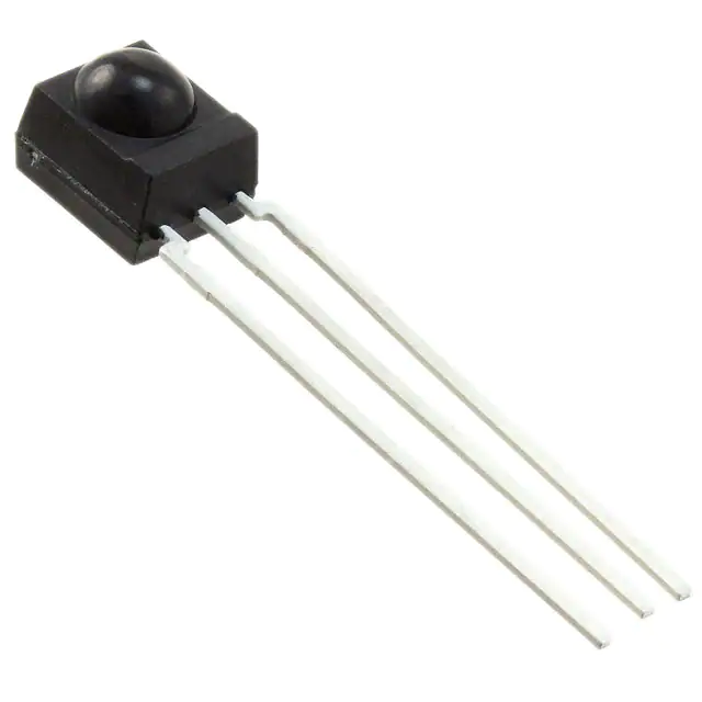
- Part No.:
- TSOP34138
- Manufacturer:
- Vishay Semiconductor Opto Division
- Category:
- Photo Detectors - Remote Receiver
- Package:
- Datasheet:
-
TSOP34138.pdf
- Description:
- SENSOR REMOTE REC 38.0KHZ 45M
- Quantity:
- Payment:

- Shipping:

Inventory:2,224
Please send an inquiry. Send us your inquiry, and we will respond immediately.
Product details
Overview
TSOP34138 from Vishay Semiconductors is an infrared (IR) receiver module optimized for short-burst remote control systems operating at 38 kHz carrier frequency, with AGC1 configuration for legacy remote protocols. It integrates a PIN photodiode and preamplifier in a molded epoxy package with built-in IR filter, delivers active-low demodulated output directly compatible with microcontrollers, and supports operation from 2.0 V to 5.5 V supply voltage.
For engineers reviewing the TSOP34138 datasheet, TSOP34138 pinout, TSOP34138 application, or TSOP34138 equivalent, key selection considerations include its ±45° horizontal directivity, 39 m typical transmission distance with TSAL6200 emitter, 0.35 mA typical supply current at 3.3 V, immunity to fluorescent lamp interference (Fig. 13), and suitability for RC5, XMP, RECS-80, RCMM, and r-map code formats.
Technical Context
The TSOP34138 implements a band-pass filter centered at 38 kHz with Δf(3 dB) = f₀/10, enabling selective detection of modulated IR signals while rejecting continuous or off-frequency noise. Its AGC1 architecture provides baseline noise suppression without aggressive gain reduction, preserving compatibility with standard remote control burst lengths (≥6 cycles/burst) and gap timing (6–70 cycles between bursts).
Internal circuitry includes a demodulator with output pulse width control (tpo constrained to tpi ± 3.5/f₀), DC-blocking and automatic gain control logic, and output stage capable of sinking 0.5 mA at ≤100 mV low-level voltage. The device operates across –25 °C to +85 °C ambient temperature and is not qualified for automotive use.
Key Specifications
| Parameter | Value and Actual Design Meaning |
|---|---|
| Carrier frequency | 38 kHz - precisely matched to common IR remote transmitters (e.g., RC5, XMP) for reliable demodulation |
| Supply voltage range | 2.0 V to 5.5 V - enables direct interface with 3.3 V and 5 V microcontroller I/O domains without level shifting |
| Supply current (typ.) | 0.35 mA at 3.3 V - enables low-power remote receiver designs with battery life extension |
| Transmission distance | 39 m with TSAL6200 emitter at 50 mA - supports full-room consumer remote control coverage |
| Minimum irradiance | 0.05 mW/m² (RC5), 0.1 mW/m² (XMP) - ensures reliable wake-up and command decoding under weak signal conditions |
| Directivity (half-angle) | ±45° - provides wide-angle reception suitable for non-line-of-sight or off-axis remote usage |
| Output polarity | Active-low - directly drives standard MCU GPIO interrupt inputs without external inversion logic |
Pinout & Package
TSOP34138 uses a 3-pin leaded surface-mount package (6.0 mm × 6.95 mm × 5.6 mm) with epoxy IR-filtered housing and standardized TSOP footprint. Pin 1 is OUT (active-low demodulated output), Pin 2 is GND (signal and power ground reference), and Pin 3 is VS (2.0–5.5 V supply input).
| Pin/Terminal | Circuit Role | Design Meaning |
|---|---|---|
| 1 - OUT | Demodulated output signal | Open-collector NPN output; sinks up to 5 mA; requires external pull-up to VS for logic-high state |
| 2 - GND | Ground reference | Common return path for photodiode bias, amplifier, and output stage; must be low-impedance |
| 3 - VS | Positive supply input | Accepts 2.0–5.5 V DC; decoupling capacitor (C1) recommended near pin for ripple suppression |
Key Features
| Feature | Design Value |
|---|---|
| Integrated PIN diode + preamplifier | Single-component solution eliminates discrete photodiode/amplifier design complexity and layout sensitivity |
| Onboard IR optical filter | Rejects visible light and ambient IR noise (e.g., sunlight, incandescent lamps), improving signal-to-noise ratio |
| AGC1 configuration | Optimized for legacy short-burst protocols (e.g., RC5) with minimal gain variation and maximum code compatibility |
| Fluorescent lamp immunity | Suppresses interference from low-modulation fluorescent sources (per Fig. 13), enabling stable operation in office/home lighting |
| Wide supply voltage range | Supports direct integration into both 3.3 V embedded systems and legacy 5 V remote control receivers |
Applications
| TV Remote Control Receiver | AC Unit IR Interface |
|---|---|
Use Scenario: Consumer television remote control system receiving commands in living room environments with mixed ambient lighting. IC Role / Device Role / Timing Role: IR signal demodulator and protocol decoder front-end, converting modulated 38 kHz IR bursts into clean digital pulses for MCU interpretation. Use Value: Enables reliable command capture at up to 39 m range with ±45° viewing angle, and rejects interference from LED/LCD TV backlights and nearby Wi-Fi routers. | Use Scenario: Wall-mounted air conditioner remote receiver operating in brightly lit commercial spaces with fluorescent lighting. IC Role / Device Role / Timing Role: Ambient-noise-immune IR front-end that filters out 20–100 kHz lamp ballast emissions before signal conditioning. Use Value: Maintains functional integrity under high ambient DC irradiance (up to 10 W/m²) and suppresses spurious outputs from Fig. 13–type fluorescent disturbances. |
| Set-Top Box Command Input | Smart Home Hub IR Gateway |
Use Scenario: Compact set-top box requiring low-profile IR reception with minimal PCB area and no external components. IC Role / Device Role / Timing Role: Self-contained IR receiver delivering active-low pulses synchronized to RC5/XMP envelope timing for direct GPIO interrupt triggering. Use Value: Eliminates need for external amplifiers, filters, or inverters; 0.35 mA supply current extends standby battery life in always-on designs. | Use Scenario: Multi-protocol smart home hub supporting legacy IR remotes (RC5, RECS-80, r-map) alongside RF and BLE interfaces. IC Role / Device Role / Timing Role: Protocol-agnostic IR signal conditioner providing standardized digital output regardless of underlying modulation scheme. Use Value: Native support for five major IR codes (RC5, XMP, RECS-80, RCMM, r-map) reduces firmware complexity and enables single-hardware IR abstraction layer. |
Equivalent & Alternatives
The following parts are listed as comparable options for similar IR receiver applications.
| Alternative Part | Technical Difference | Application Difference | Selection Advice |
|---|---|---|---|
| TSOP32138 | Different pinout: Pin 1 = OUT, Pin 2 = VS, Pin 3 = GND; identical electrical/optical specs and AGC1 configuration | Requires PCB layout revision due to swapped VS/GND pins; same performance in noise immunity and range | Select when existing board uses TSOP32x footprint or when GND routing constraints favor VS-on-Pin2 placement |
| TSOP34338 | AGC3 configuration instead of AGC1; higher noise suppression but reduced compatibility with long-burst or low-duty-cycle codes | Better suited for noisy industrial environments with strong EMI; less tolerant of marginal signal strength or non-standard burst timing | Select when fluorescent lamp interference exceeds Fig. 13 levels or when operating near Wi-Fi routers and switching power supplies |
Compared with TSOP32138, TSOP34138 offers identical functionality with reversed supply/ground pinout-requiring layout change but no firmware or performance trade-off. Against TSOP34338, TSOP34138 prioritizes protocol compatibility over noise rejection, making it optimal for consumer remote ecosystems where RC5 and XMP dominance demands minimal false-trigger risk.
Availability
TSOP34138 is available at Aetrix Electronics and suitable for TV remote control receivers, HVAC IR interfaces, set-top box command inputs, and smart home hub IR gateways requiring stable component supply, consistent parametric performance, and long-term manufacturing continuity.
Supply support for TSOP34138 includes scheduled delivery planning, volume procurement assistance, BOM continuity management, traceable sourcing, and lifecycle availability coordination for OEM customers, industrial embedded developers, connected-device designers, and electronics production programs.
Manufacturer
Vishay Intertechnology is a global semiconductor manufacturer specializing in discrete components, sensors, and optoelectronics, with emphasis on reliability, precision, and application-specific integration.
The TSOP341xx series belongs to Vishay's IR receiver module product line, engineered specifically for short-burst remote control systems in consumer electronics where noise immunity, low power, and multi-code compatibility are critical.
FAQ
What is the carrier frequency supported by TSOP34138?
The TSOP34138 is tuned to a nominal carrier frequency of 38 kHz, with a 3 dB bandwidth of ±3.8 kHz (Δf = f₀/10). This matches industry-standard remote control protocols including RC5, XMP, RECS-80, RCMM, and r-map. Its center frequency tolerance and selectivity ensure robust demodulation of 38 kHz-modulated IR signals while rejecting adjacent frequencies such as 36 kHz or 40 kHz.
Does TSOP34138 require external components for basic operation?
TSOP34138 operates autonomously with only a pull-up resistor on the OUT pin and optional decoupling capacitor (C1) on the VS pin. The datasheet recommends a 100 nF ceramic capacitor placed close to Pin 3 (VS) when supply ripple or spikes exceed specification limits. No external amplifier, filter, or level shifter is needed-its integrated PIN diode, preamplifier, and demodulator deliver ready-to-decode digital output.
Is TSOP34138 qualified for automotive applications?
No, TSOP34138 is not qualified to AEC-Q200 or any automotive-grade reliability standard. The datasheet explicitly states "These components have not been qualified to automotive specifications." Its operating temperature range is –25 °C to +85 °C, and it lacks automotive-specific stress testing, qualification reporting, or PPAP documentation. For automotive infotainment or climate control IR receivers, Vishay's automotive-qualified alternatives must be selected.
How does TSOP34138 handle ambient light interference?
TSOP34138 incorporates an epoxy-integrated IR passband filter centered at 950 nm and employs AGC1-based dynamic gain control to suppress DC and low-frequency ambient light (e.g., tungsten bulbs, sunlight). It rejects continuous or slowly varying irradiance up to 10 W/m² (≈8.2 klx daylight) and is specifically designed to ignore interference patterns from low-modulation fluorescent lamps per Figure 13 in the datasheet.
What is the minimum burst length required for reliable detection by TSOP34138?
TSOP34138 requires a minimum burst length of 6 carrier cycles at 38 kHz (≈158 µs), as specified in the "SUITABLE DATA FORMAT" section. Bursts shorter than this threshold may not trigger valid output pulses. Additionally, a gap time of 6–70 cycles (158–1.84 ms) is required between consecutive bursts to ensure proper AGC recovery and avoid false triggering.
TSOP34138 Specifications
- Product attributes
- Attribute value
- Manufacturer:
- Vishay Semiconductor Opto Division
- Series:
- -
- Packaging:
- Tube
- Product Status:
- Active
- Sensing Distance:
- 45m
- B.P.F. Center Frequency:
- 38.0kHz
- Voltage - Supply:
- 2.5 V ~ 5.5 V
- Current - Supply:
- 350 µA
- Orientation:
- Side View
- Mounting Type:
- Through Hole
- Operating Temperature:
- -25°C ~ 85°C
TSOP34138 FAQ
1.How can I place an order for TSOP34138 through Aetrix?
Please submit a Request for Quotation (RFQ) for TSOP34138 on Aetrix. Our sales agent will provide a competitive quotation and guide you through the order confirmation once you accept the terms.
2.Are the price and stock information for TSOP34138 reliable?
The price and inventory of TSOP34138 are updated periodically and may fluctuate due to market conditions. Stock and pricing data are typically refreshed every 24 hours. Quotation validity for TSOP34138 is usually 5 days.
3.What payment methods are accepted for TSOP34138?
We accept Wire Transfer, PayPal, Credit Card, Western Union, MoneyGram, and Escrow for TSOP34138 transactions.
Note: Certain payment methods may incur a processing fee.
4.How is shipping managed for TSOP34138?
TSOP34138 orders can be shipped via leading logistics carriers, including DHL, UPS, FedEx, TNT, or Registered Mail.
Once your TSOP34138 order is processed, you will receive an email with the shipment details and tracking number.
Note: Tracking information may take up to 24 hours to appear. Express delivery typically takes 3–5 business days.
5.How can I obtain technical support or documentation for TSOP34138?
For technical support, including TSOP34138 datasheets, pinout diagrams, or application guidance, please contact our engineering support team. They can provide detailed documentation and assistance for your TSOP34138 requirements.
6.How does Aetrix verify that TSOP34138 is sourced from the original manufacturer or authorized distributors?
All TSOP34138 products on Aetrix are procured from qualified distributors and authorized channels. Our dedicated quality assurance team conducts strict verification, including traceability checks and, if necessary, third-party testing. This ensures that TSOP34138 meets industry standards.
7.What is the process for return or replacement of TSOP34138?
All TSOP34138 units undergo pre-shipment inspection (PSI). If there is an issue with TSOP34138, returns or replacements are accepted under the following conditions:
1.Quantity discrepancies, incorrect items, or visible external defects (such as breakage or corrosion), acknowledged by Aetrix.
2.The issue is reported within 90 days of delivery.
3.The TSOP34138 part is unused and in its original packaging.
Return procedure for TSOP34138:
1.Submit a request within 90 days.
2.Obtain a Return Material Authorization (RMA) from Aetrix.
TSOP34138 Tags
-
TSOP38238
Vishay Semiconductor Opto Division
-
VSOP38338
Vishay Semiconductor Opto Division
.jpg)
-
TSOP75436TT
Vishay Semiconductor Opto Division
.jpg)
-
TSOP75238TT
Vishay Semiconductor Opto Division
-
TSSP4038
Vishay Semiconductor Opto Division
-
TSSP4038SS1XB
Vishay Semiconductor Opto Division

-
TSSP6038TT
Vishay Semiconductor Opto Division
.jpg)
-
TSOP75340TT
Vishay Semiconductor Opto Division
.jpg)
-
TSOP75338TT
Vishay Semiconductor Opto Division
-
TSOP57238TT1
Vishay Semiconductor Opto Division
-
TSSP57038ETT1
Vishay Semiconductor Opto Division
_W.jpg)
-
TSOP75338WTT
Vishay Semiconductor Opto Division
Tech Hub

Comparator circuit design covering voltage thresholds, input limits, open-collector outputs, LM393 wiring, op-amp differences, hysteresis, timing, window detection and practical fault diagnosis.
Schmitt triggers use separate rising and falling thresholds to stabilize slow or noisy signals. This guide covers hysteresis, 74HC14 and 74HCT14 selection, comparator calculations, RC oscillators and p…
Counterfeit components can hide behind convincing markings and passing basic function tests. This engineering reference covers source traceability, external inspection, X-ray, XRF, electrical testing, …
A practical engineering and sourcing framework covering lifecycle verification, lifetime-buy calculations, replacement qualification, supplier checks and counterfeit-risk controls.
TTL and CMOS logic families differ in thresholds, loading, output drive, power and timing. This engineering guide compares 74HC and 74HCT, calculates noise margins and checks 3.3 V/5 V compatibility.
A practical engineering guide to 3.3V and 5V logic compatibility, input thresholds, resistor dividers, translator ICs, MOSFET level shifting, I2C pull-ups, timing limits and power-sequencing risks.
The 74HC595 uses push-pull logic outputs, while the TPIC6B595 uses 50 V open-drain DMOS sinks for higher-power loads. This guide compares timing, current limits, 3.3 V interfacing, load wiring, thermal…
The 74HC595 converts serial data into eight stable parallel outputs. This guide covers pin functions, shift and storage timing, OE and MR behavior, drive-current limits, cascading, voltage compatibilit…
A technical comparison of level-sensitive latches and edge-triggered flip-flops, covering timing windows, setup and hold limits, master–slave operation, time borrowing, race-through, HDL inference and…
A D latch stores one bit while Enable controls when data can pass. This reference covers gate-level operation, truth tables, transparency, setup and hold timing, LE versus OE, common ICs and practical …









