Send an Inquiry

To receive a quote for your project, please fill in the following information, and we’ll get back to you promptly.

Name*
Company*
Email Address*
Phone/WhatsApp
Part Number*
Quantity*
Message
Submit Inventory List

Please fill in the following information, and we’ll get back to you promptly.

Name*
Company*
Email Address*
Phone/WhatsApp
Upload My List
Message

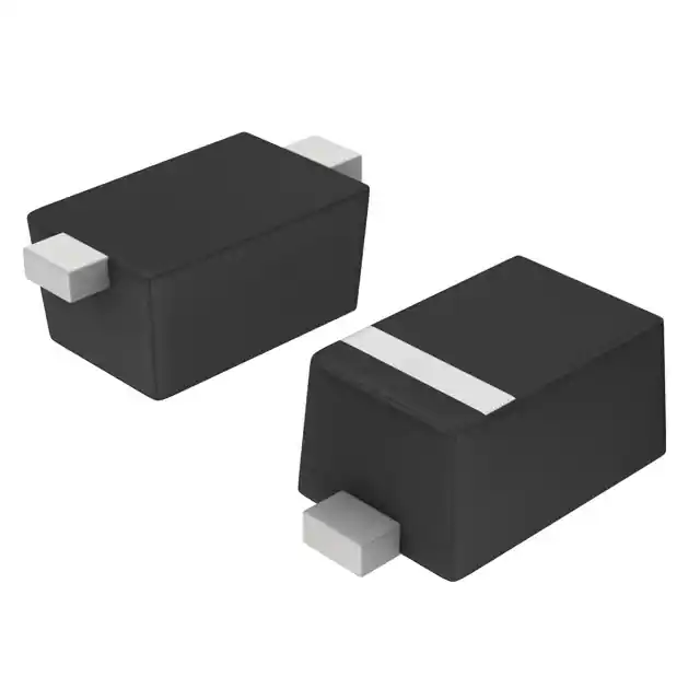
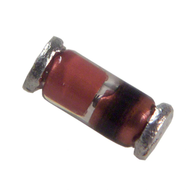
Vishay General Semiconductor - Diodes Division TZMC33-GS18
Part No.:
TZMC33-GS18
Manufacturer:
Vishay General Semiconductor - Diodes Division
Category:
Single Zener Diodes
Package:
DO-213AC, MINI-MELF, SOD-80
Datasheet:
AetrixTZMC33-GS18.pdf
Description:
DIODE ZENER 33V 500MW SOD80
Quantity:
Payment:
Payment
Shipping:
Shipping

Inventory:9,032

Please send an inquiry. Send us your inquiry, and we will respond immediately.

Part Number
Quantity*
Price
Name*
Company
Email*
Comments

Product details

Overview

TZMC33-GS18 from Vishay Semiconductors is a MiniMELF (SOD-80) packaged silicon Zener diode with nominal zener voltage 33 V, ±5 % tolerance, 5 mA test current, < 0.1 μA reverse leakage at 95 % VZmin, and 24 Ω dynamic resistance at IZT; used for precision voltage stabilization in low-power analog reference and regulator feedback paths.

For engineers reviewing the TZMC33-GS18 datasheet, TZMC33-GS18 pinout, TZMC33-GS18 application, or TZMC33-GS18 equivalent, this page delivers verified electrical specs, package dimensions, thermal behavior, real-world stabilization use cases, and validated alternative parts for design-in and BOM optimization.

Technical Context

The TZMC33-GS18 operates as a two-terminal voltage reference device relying on controlled avalanche breakdown in its p-n junction. Its temperature coefficient of zener voltage is +0.04 %/K to +0.12 %/K, indicating positive drift above ~6.2 V, and it maintains stable regulation under pulse and DC conditions up to 500 mW total power dissipation.

Designed for high-stability, low-noise operation, the device features very sharp reverse characteristics and low reverse current (< 0.1 μA at 31.35 V), enabling accurate clamping and reference functions in battery-powered and precision instrumentation circuits where long-term drift and thermal hysteresis must be minimized.

Key Specifications

ParameterValue and Actual Design Meaning
Zener voltage (VZ)31.0–35.0 V (nominal 33 V; ±5 % tolerance ensures predictable clamping within 1.65 V window)
Test current (IZT)5 mA (standard operating point for VZ specification; defines bias condition for datasheet parameters)
Dynamic resistance (ZZ)24 Ω (low impedance at 5 mA enables tight regulation against load transients)
Reverse leakage (IR)< 0.1 μA at 31.35 V (enables ultra-low standby current in always-on reference circuits)
Power dissipation (Ptot)500 mW (supports continuous operation at 33 V with ≤15 mA average current)
Temperature coefficient (TKVZ)+0.04 to +0.12 %/K (positive drift allows predictable compensation in multi-diode references)
Junction temperature (Tj)175 °C max (supports operation in industrial environments with elevated ambient temperatures)

Pinout & Package

MiniMELF (SOD-80) glass-body cylindrical package with axial leads; cathode identified by a band or indentation near one end. Total weight ≈31 mg; UL 94 V-0 molding compound; MSL level 1; compatible with standard reflow profiles (peak 260 °C).

Pin/TerminalCircuit RoleDesign Meaning
AnodeForward conduction terminal / low-side connectionConnected to ground or lower potential node in shunt regulator configuration
CathodeZener breakdown terminal / high-side connectionConnected to input voltage source; regulates voltage across load tied between cathode and anode

Key Features

FeatureDesign Value
Very sharp reverse characteristicEnables precise knee detection and minimal voltage overshoot during transient clamping
Low reverse current level (< 0.1 μA)Reduces quiescent power loss in battery-critical applications such as IoT sensor nodes
Very high stabilitySupports long-term voltage reference integrity over 10+ years in unregulated environments
Low noiseMinimizes added jitter in analog signal chains and precision ADC reference buffers
VZ tolerance ±5 %Allows direct use without post-selection in cost-sensitive consumer and industrial designs

Applications

Industrial Sensor Signal ConditioningUSB-C Power Delivery Clamp

Use Scenario: Stabilizing excitation voltage for bridge-based pressure sensors in factory automation PLC modules.

IC Role / Device Role / Timing Role: Shunt voltage reference providing fixed 33 V bias to Wheatstone bridge, rejecting supply ripple.

Use Value: Maintains bridge output linearity within ±0.05 % full-scale error despite ±10 % input rail variation.

Use Scenario: Overvoltage protection clamp on VBUS line in USB-C sink port during hot-plug events.

IC Role / Device Role / Timing Role: Fast-acting crowbar element limiting VBUS to 33 V during 20 V PD negotiation faults.

Use Value: Limits fault energy to < 10 mJ with < 100 ns response, preventing downstream PMIC latch-up.

Programmable Logic Controller (PLC) Analog Input ProtectionMedical Infusion Pump Reference

Use Scenario: Front-end overvoltage clamp on 4–20 mA loop receiver inputs exposed to field wiring surges.

IC Role / Device Role / Timing Role: Passive shunt limiter absorbing transient energy before signal conditioning op-amps.

Use Value: Withstands 1 kV/μs fast transients per IEC 61000-4-5 Level 3 without parameter shift or degradation.

Use Scenario: Precision 33 V reference for DAC-controlled motor driver in Class II medical infusion pump.

IC Role / Device Role / Timing Role: Stable voltage reference for 16-bit DAC generating calibrated flow-rate command signals.

Use Value: Delivers < 10 ppm/°C drift over 0–50 °C, meeting IEC 60601-1 accuracy requirements for dose control.

Equivalent & Alternatives

The following parts are listed as comparable options for similar Zener diode voltage stabilization applications.

Alternative PartTechnical DifferenceApplication DifferenceSelection Advice
BZX55C33-TRDO-35 package; 500 mW rating; ±5 % VZ; 25 Ω ZZ at 5 mA; higher RthJA (625 K/W)Larger footprint; less suitable for high-density PCBs; lower thermal performance in confined layoutsSelect when legacy DO-35 compatibility or through-hole assembly is required
MMSZ5256B-TPSOD-123 package; 500 mW; ±5 % VZ; 27 Ω ZZ; MSL level 1; 1000 units/reel minimum orderSurface-mount but larger body than MiniMELF; higher capacitance (40 pF vs. 15 pF typical)Select when automated pick-and-place compatibility with standard SOD-123 feeders is prioritized

Compared with TZMC33-GS18, BZX55C33-TR offers identical electrical specs but inferior thermal resistance and larger size, while MMSZ5256B-TP trades MiniMELF's low capacitance and high stability for broader SMT process support-making TZMC33-GS18 optimal for space-constrained, low-noise, high-reliability analog references.

Availability

TZMC33-GS18 is available at Aetrix Electronics and suitable for industrial sensor conditioning, USB-C power delivery protection, and medical infusion pump reference circuits requiring stable component supply, consistent parametric performance, and long-lifecycle availability.

Supply support for TZMC33-GS18 includes scheduled delivery planning, volume procurement assistance, BOM continuity management, traceable sourcing, and lifecycle availability coordination for OEM customers, industrial embedded developers, connected-device designers, and electronics production programs.

Manufacturer

Vishay Semiconductors is a global manufacturer of discrete semiconductors and passive components, specializing in high-reliability diodes, MOSFETs, optoelectronics, and resistive sensors.

The TZM-Series Zener diodes-including TZMC33-GS18-are engineered for precision voltage regulation in demanding analog, industrial, and automotive subsystems where stability, low noise, and long-term repeatability are critical.

FAQ

What is the maximum continuous power dissipation for TZMC33-GS18?

The TZMC33-GS18 has a maximum total power dissipation (Ptot) of 500 mW at Tamb = 25 °C with RthJA ≤ 300 K/W. Derating is required above 25 °C ambient-approximately 3.3 mW/°C above that point per the datasheet's Ptot vs. Tamb curve. This limit ensures safe junction temperature operation below 175 °C in typical PCB layouts.

Does TZMC33-GS18 have a specified reverse leakage current at elevated temperature?

Yes, TZMC33-GS18 specifies reverse leakage current (IR) ≤ 0.1 μA at VR = 31.35 V (95 % VZmin) and Tj = 25 °C. At Tj = 150 °C, IR remains ≤ 2 μA per note (1) in the Vishay datasheet 84122, confirming robust high-temperature blocking capability essential for under-hood or industrial applications.

What is the thermal resistance from junction to ambient (RthJA) for TZMC33-GS18 on a standard PCB?

The TZMC33-GS18 exhibits a junction-to-ambient thermal resistance (RthJA) of 500 K/W when mounted on a standard FR-4 PCB measuring 50 mm × 50 mm × 1.6 mm. This value reflects real-world board-level cooling-not theoretical free-air conditions-and directly informs thermal design margins when calculating worst-case junction temperature under sustained 33 V bias.

Can TZMC33-GS18 be used in series or parallel configurations for higher voltage or current handling?

TZMC33-GS18 is not recommended for parallel operation due to mismatched dynamic resistance and thermal runaway risk. In series, multiple TZMC33-GS18 devices can achieve higher regulated voltages (e.g., two in series = ~66 V), but individual unit tolerances compound (±10 % total), and thermal coupling must be managed to avoid imbalance-designs should include balancing resistors per Vishay application guidance.

Is TZMC33-GS18 compliant with RoHS and REACH regulations?

Yes, TZMC33-GS18 complies with RoHS Directive 2011/65/EU and REACH Regulation (EC) No. 1907/2006, as confirmed by Vishay's material declarations (document 99912). The MiniMELF package uses lead-free terminations and UL 94 V-0 compliant molding compound, supporting environmentally conscious manufacturing and export compliance.

TZMC33-GS18 Specifications

Product attributes
Attribute value
Manufacturer:
Vishay General Semiconductor - Diodes Division
Series:
TZM
Package/Case:
DO-213AC, MINI-MELF, SOD-80
Packaging:
Tape & Reel (TR)
Product Status:
Active
Voltage - Zener (Nom) (Vz):
33 V
Tolerance:
±5%
Power - Max:
500 mW
Impedance (Max) (Zzt):
80 Ohms
Current - Reverse Leakage @ Vr:
100 nA @ 24 V
Voltage - Forward (Vf) (Max) @ If:
1.5 V @ 200 mA
Operating Temperature:
175°C
Grade:
Automotive
Qualification:
AEC-Q101
Mounting Type:
Surface Mount
Supplier Device Package:
SOD-80 MiniMELF

TZMC33-GS18 FAQ

1.How can I place an order for TZMC33-GS18 through Aetrix?

Please submit a Request for Quotation (RFQ) for TZMC33-GS18 on Aetrix. Our sales agent will provide a competitive quotation and guide you through the order confirmation once you accept the terms.

2.Are the price and stock information for TZMC33-GS18 reliable?

The price and inventory of TZMC33-GS18 are updated periodically and may fluctuate due to market conditions. Stock and pricing data are typically refreshed every 24 hours. Quotation validity for TZMC33-GS18 is usually 5 days.

3.What payment methods are accepted for TZMC33-GS18?

We accept Wire Transfer, PayPal, Credit Card, Western Union, MoneyGram, and Escrow for TZMC33-GS18 transactions.

Note: Certain payment methods may incur a processing fee.

4.How is shipping managed for TZMC33-GS18?

TZMC33-GS18 orders can be shipped via leading logistics carriers, including DHL, UPS, FedEx, TNT, or Registered Mail.

Once your TZMC33-GS18 order is processed, you will receive an email with the shipment details and tracking number.

Note: Tracking information may take up to 24 hours to appear. Express delivery typically takes 3–5 business days.

5.How can I obtain technical support or documentation for TZMC33-GS18?

For technical support, including TZMC33-GS18 datasheets, pinout diagrams, or application guidance, please contact our engineering support team. They can provide detailed documentation and assistance for your TZMC33-GS18 requirements.

6.How does Aetrix verify that TZMC33-GS18 is sourced from the original manufacturer or authorized distributors?

All TZMC33-GS18 products on Aetrix are procured from qualified distributors and authorized channels. Our dedicated quality assurance team conducts strict verification, including traceability checks and, if necessary, third-party testing. This ensures that TZMC33-GS18 meets industry standards.

7.What is the process for return or replacement of TZMC33-GS18?

All TZMC33-GS18 units undergo pre-shipment inspection (PSI). If there is an issue with TZMC33-GS18, returns or replacements are accepted under the following conditions:

1.Quantity discrepancies, incorrect items, or visible external defects (such as breakage or corrosion), acknowledged by Aetrix.

2.The issue is reported within 90 days of delivery.

3.The TZMC33-GS18 part is unused and in its original packaging.

Return procedure for TZMC33-GS18:

1.Submit a request within 90 days.

2.Obtain a Return Material Authorization (RMA) from Aetrix.

TZMC33-GS18 Tags
  • TZMC33-GS18
  • TZMC33-GS18 PDF
  • TZMC33-GS18 Datasheet
  • TZMC33-GS18 Specifications
  • TZMC33-GS18 Images
  • Vishay General Semiconductor - Diodes Division
  • Vishay General Semiconductor - Diodes Division TZMC33-GS18
  • Buy TZMC33-GS18
  • TZMC33-GS18 Price
  • TZMC33-GS18 Distributor
  • TZMC33-GS18 Supplier
  • TZMC33-GS18 Wholesale
Related Products
MMBZ5240B-7-F
MMBZ5240B-7-F

Diodes Incorporated

BZT52C5V6T-7
BZT52C5V6T-7

Diodes Incorporated

MMSZ5231B-7-F
MMSZ5231B-7-F

Diodes Incorporated

BZT52C15-7-F
BZT52C15-7-F

Diodes Incorporated

BZX84C3V3LT1G
BZX84C3V3LT1G

onsemi

MMSZ5245BS-7-F
MMSZ5245BS-7-F

Diodes Incorporated

MMSZ4682T1G
MMSZ4682T1G

onsemi

BZT52C15S-7-F
BZT52C15S-7-F

Diodes Incorporated

MM5Z5V1ST1G
MM5Z5V1ST1G

onsemi

SMAJ4744A-TP
SMAJ4744A-TP

Micro Commercial Co

BZT52C3V6LP-7
BZT52C3V6LP-7

Diodes Incorporated

SMAZ12-13-F
SMAZ12-13-F

Diodes Incorporated

Tech Hub

Search

Search

PRODUCT

PRODUCT

PHONE

PHONE

USER

USER